coil ignition JAGUAR X308 1998 2.G Workshop Manual
[x] Cancel search | Manufacturer: JAGUAR, Model Year: 1998, Model line: X308, Model: JAGUAR X308 1998 2.GPages: 2490, PDF Size: 69.81 MB
Page 14 of 2490

303‐07: En gine Ignition
Specification
Diagnosis and Testing
Engine Ignition
Diagnosis and Testing
Engine Ignition
Inspection and Verification
Driver Information Chart
Default mode Definitions
Diagnostic Trouble Code (DTC) index
Pinpoint Tests
Removal and Installation
Ignition Coil ‐On ‐Plug LH (18.20.44)
Ignition Coil ‐On ‐Plug RH (18.20.43)
Ignition Module (18.20.30)
Spark Plugs (18.20.02)
303‐08: En
gine Emission Control
Specification
Diagnosis and Testing
Engine Emission Control
Inspection and Verification
Diagnostic Trouble Code (DTC) Index
Pinpoint Tests
Removal and Installation
Exhaust Gas Recirculation (EGR) Valve (17.45.01)
Exhaust Manifold to Exhaust Gas Recirculation (E
GR) Valve Tube (17.45.11)
303‐12: Intake Air Distribution and Filtering
Removal and Installation
Air Cleaner (19.10.05)
Air Cleaner Element (19.10.08)
Charge Air Cooler LH (18.50.19)
Charge Air Cooler RH (18.50.18)
Charge Air Cooler Gasket LH (18.50.22)
Charge Air Cooler Gasket RH (18.50.21)
Supercharger (18.50.
15)
Page 45 of 2490
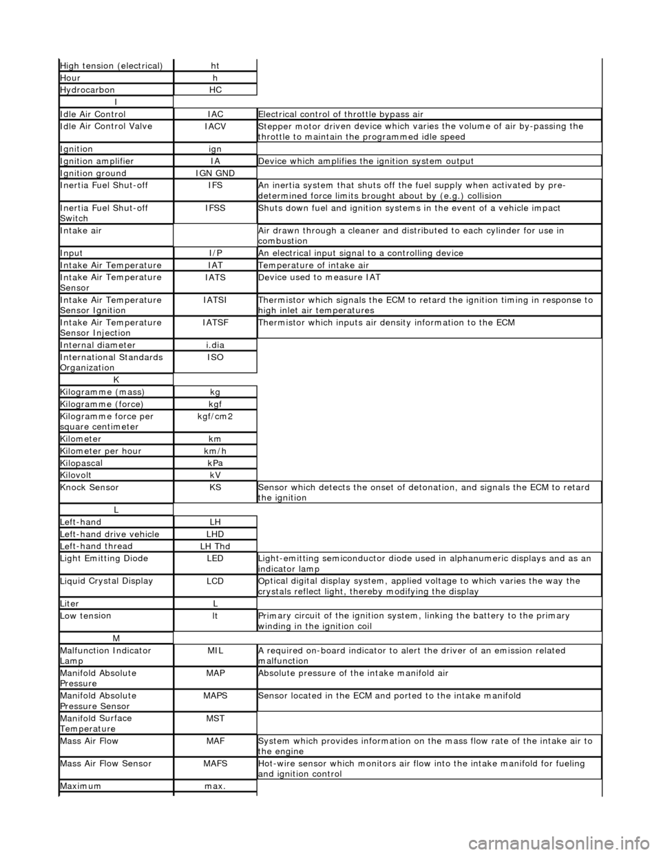
High
tension (electrical)
ht
Hourh
Hydro
carbon
HC
I
Idl
e Air Control
IACEl
ectrical control of throttle bypass air
Idl
e Air Control Valve
IACVStepper motor dri
ven device which vari
es the volume of air by-passing the
throttle to maintain the programmed idle speed
Ignitionign
Ignition am
plifier
IAD
evice which amplifies the i
gniti
on system output
Ignition groundIGN GND
In
ertia Fuel Shut-off
IFSAn
inertia system that shuts off the fuel supply when activated by pre-
determined force limits brough t about by (e.g.) collision
In
ertia Fuel Shut-off
Switch
IFSSShut
s down fuel and ignition systems in the event of a vehicle impact
Inta
ke air
Air drawn t
hrough a cleaner and distri
buted to each cylinder for use in
combustion
InputI/PAn
electrical input signal to a controlling device
Inta
ke Air Temperature
IATTem
perature of intake air
Inta
ke Air Temperature
Sensor
IATSDe
vice used to measure IAT
Inta
ke Air Temperature
Sensor Ignition
IATSITherm
istor which signals the ECM to retard
the ignition timing in response to
high inlet air temperatures
Inta
ke Air Temperature
Sensor Injection
IATSFTher
mistor which inputs air density information to the ECM
Internal diameteri.
dia
Inte
rnational Standards
Organization
ISO
K
Kilogramme (mass)kg
Kilogram
me (force)
kg
f
Ki
logramme force per
square centimeter
kg
f/cm2
Kilom
eter
km
Ki
lometer per hour
km
/h
Kilopasc
al
kP
a
KilovoltkV
Knock
Sensor
KSSens
or which detects the onset of detonation, and signals the ECM to retard
the ignition
L
Le
ft-hand
LH
Left-hand drive veh
icle
LHD
Le
ft-hand thread
LH Thd
Ligh
t Emitting Diode
LEDLigh
t-emitting semiconductor diode used
in alphanumeric displays and as an
indicator lamp
Liqu
id Crystal Display
LCDOp
tical digital display system, applied voltage to which varies the way the
crystals reflect light, thereby modifying the display
LiterL
Low ten
sion
ltPrim
ary circuit of the ignition system, linking the battery to the primary
winding in the ignition coil
M
Malfu
nction Indicator
Lamp
MILA
required on-board indicator to aler
t the driver of an emission related
malfunction
Mani
fold Absolute
Pressure
MAPAbsolute pressure o
f the intake manifold air
Mani
fold Absolute
Pressure Sensor
MAPSSensor loca
ted in the ECM and
ported to the intake manifold
Manifol
d Surface
Temperature
MST
Mass Ai
r Flow
MAFSy
stem which provides inform
ation on the mass flow rate of the intake air to
the engine
Mass Ai
r Flow Sensor
MAFSHot-wi
re sensor which monitors air flow
into the intake manifold for fueling
and ignition control
Maxim
um
max.
Page 528 of 2490
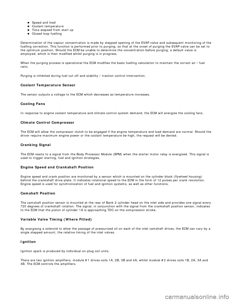
Speed an
d load
Coo
l
ant temperature
Ti
me el
apsed from start up
Cl
osed l
oop fuelling
Determination of the vapour concentration is made by stepped opening of the EVAP valve and subsequent monitoring of the
fuelling correction. This function is performed prior to purging, so that at the onse t of purging the EVAP valve can be set to
the optimum position. Should the ECM be unable to determine the concentration before purging, a default value is
employed, which is then modified whilst purging is in progress.
When the purging process is operational th e ECM modifies the basic fuelling calculation to maintain the correct air / fuel
ratio.
Purging is inhibited during fuel cut-off and stability / traction control intervention.
Coolant Temperature Sen
sor
Th
e
sensor outputs a voltage to the ECM which decreases as temperature increases.
Cooling Fans
In response to engi
ne coolant temperat
u
re and climate control system demand, the ECM will energize the cooling fans.
Climate Control Compressor
The E
C
M will allow the compressor clutch to be engaged if th
e engine temperature and load demand are normal. Should the
driver require maximum engine powe r or the coolant temperature be high, the request will be denied.
Cranking Signal
The ECM reacts to a signal fr
om th
e Body Processor Module (BPM) when the starter motor relay is energi
zed. This signal is
used to trigger starting, fu el and ignition strategies.
Engine Speed and Cranksh
aft Position
Engine
speed and cran
k position are moni
tored by a sensor which is mounted on the cylinder block (flywheel housing)
behind the crankshaft drive plat e. It indicates rotational speed to the ECM in the form of 12 pulses per crank revolution.
Engine speed is used for synchronization of fuel an d ignition systems, as well as other functions.
Camshaft Position
The ca
mshaft position sensor is mounted at
the rear of Bank 2 cylinder head on the inlet side and provides one signal every
720 degrees of crankshaft rotation. The signal, in conjunction with the signal from the crankshaft position sensor, indicates
to the ECM that the piston of cylinder 1A is approaching TDC on the compression stroke.
Variable Valve
Timing (Where Fitted)
By energi
si
ng a solenoid to allow the pass
age of pressurized oil on each of the inle t camshaft drives, the ECM can vary by a
single stepped amount, the relati ve timing of the inlet valves.
Ign
ition
Ignit
i
on spark is produced by
individual on-plug coil units.
There are two ignition amplifiers; module #1 drives coils 1A, 2B, 3B and 4A, whilst module #2 drives coils 1B, 2A, 3A and
4B. The ECM controls the amplifiers.
Page 548 of 2490
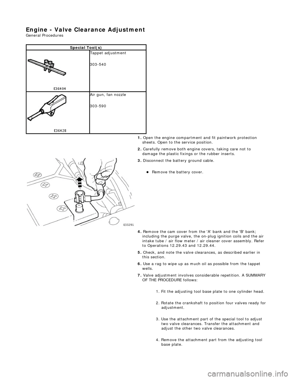
En
gine - Valve Clea
rance Adjustment
Gene
ral Procedures
S
p
ecial Tool(s)
Tappet adjustment
3
03-
540
Ai
r gun, fan nozzl
e
303-590
1. Open the engine compartment and fit paintwork protection
sheets. Open to the service position.
2. Carefully remove both engine covers, taking care not to
damage the plasti c fixings or the rubber inserts.
3. Disc
onnect the batt
ery ground cable.
Re
move the battery cover.
4. Remove the cam cover from the 'A' bank and the 'B' bank;
including the purge valve, the on-plug ignition coils and the air
intake tube / air flow meter / air cleaner cover assembly. Refer
to Operations 12.29.43 and 12.29.44.
5. Check, and note the valve cleara nces, as described earlier in
this section.
6. Use a rag to wipe up as much oil as possible from the tappet
wells.
7. Valve adjustment involves considerable repetition. A SUMMARY
OF THE PROCEDURE follows:
1. Fit the adjusting tool base plate to one cylinder head.
2. Rotate the crankshaft to position four valves ready for
adjustment.
3. Use the attachment part of the special tool to adjust two valve clearances. Transfer the attachment and
adjust the other two valve clearances.
4. Remove the attachment pa rt from the adjusting tool
base plate.
Page 551 of 2490
E
ngine - Valve Clearance Check
Gen
eral Procedures
1.
Open the engine compartment and fit paintwork protection
sheets. Open to the service position.
2. Carefully remove both engine covers, taking care not to
damage the plasti c fixings or the rubber inserts.
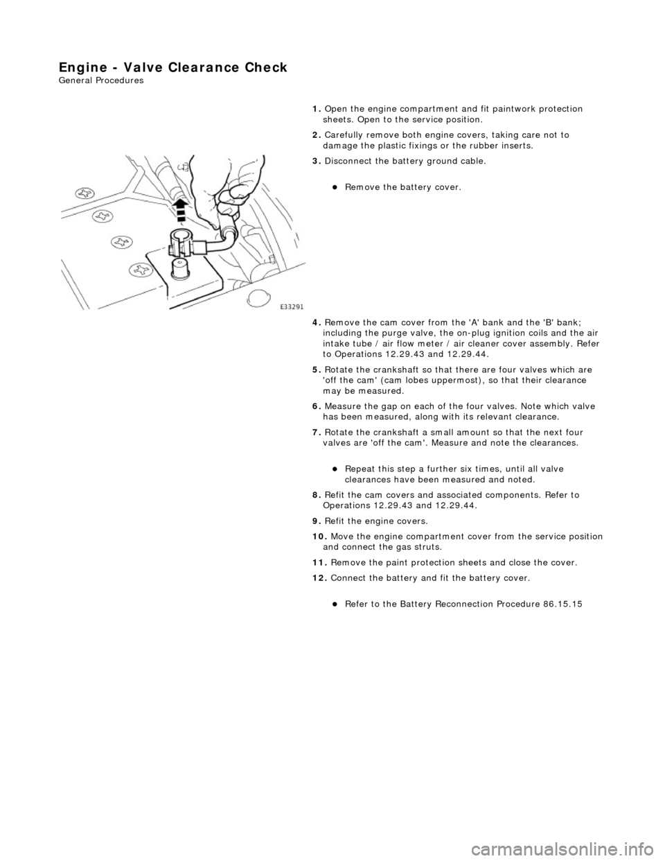
3. Di
sconnect the batt
ery ground cable.
R
emove the battery cover.
4. Remove the cam cover from the 'A' bank and the 'B' bank;
including the purge valve, the on-plug ignition coils and the air
intake tube / air flow meter / air cleaner cover assembly. Refer
to Operations 12.29.43 and 12.29.44.
5. Rotate the crankshaft so that there are four valves which are
'off the cam' (cam lobes upperm ost), so that their clearance
may be measured.
6. Measure the gap on each of the four valves. Note which valve
has been measured, along with its relevant clearance.
7. Rotate the crankshaft a small am ount so that the next four
valves are 'off the cam'. Measure and note the clearances.
Re
peat this step
a further six times, until all valve
clearances have been measured and noted.
8. Refit the cam covers and associated components. Refer to
Operations 12.29.43 and 12.29.44.
9. Refit the engine covers.
10. Move the engine compartment cover from the service position
and connect the gas struts.
11. Remove the paint protection sheets and close the cover.
12. Connect the battery and fit the battery cover.
Re
fer to the Battery Reconnection Procedure 86.15.15
Page 644 of 2490
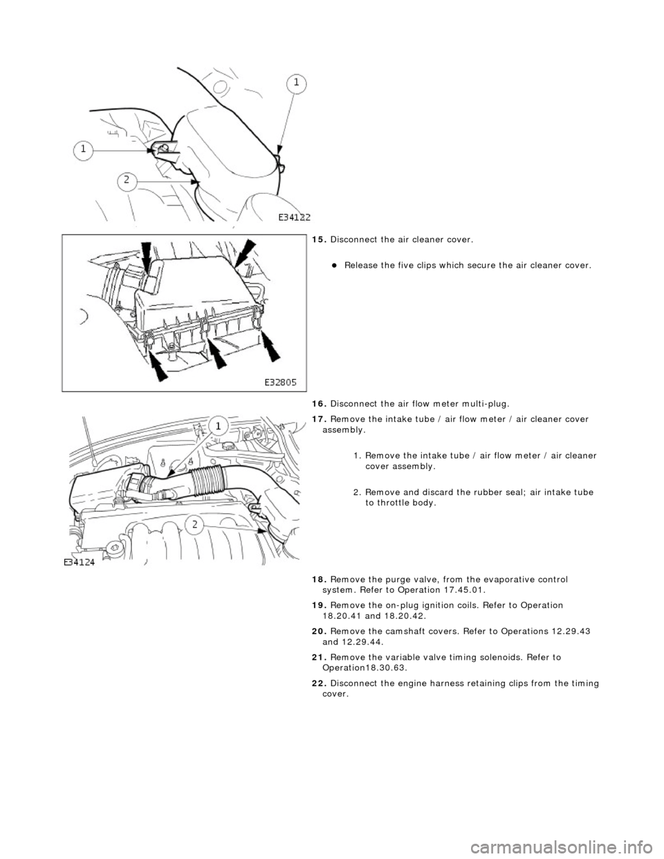
15. Di
sconnect the air cleaner cover.
R
e
lease the five clips which se
cure the air cleaner cover.
16. Disconnect the air flow meter multi-plug.
17 . R
emove the intake tube / air
flow meter / air cleaner cover
assembly.
1. Remove the intake tube / air flow meter / air cleaner
cover assembly.
2. Remove and discard the ru bber seal; air intake tube
to throttle body.
18. Remove the purge valve, fro m the evaporative control
system. Refer to Operation 17.45.01.
19. Remove the on-plug ignition coils. Refer to Operation
18.20.41 and 18.20.42.
20. Remove the camshaft covers. Refer to Operations 12.29.43
and 12.29.44.
21. Remove the variable valve ti ming solenoids. Refer to
Operation18.30.63.
22. Disconnect the engine harness retaining clips from the timing
cover.
Page 648 of 2490
8. Re
fit the variable valve timing
solenoids. Refer to Operation
18.30.63.
9. Refit the camshaft covers. Refer to Operations 12.29.43.and
12.29.44.
10. Refit the on-plug ignition coils and coil covers. Refer to
Operation 18.20.41 and 18.20.42.
11. Refit the purge valve. Refer to Operation 17.45.01.
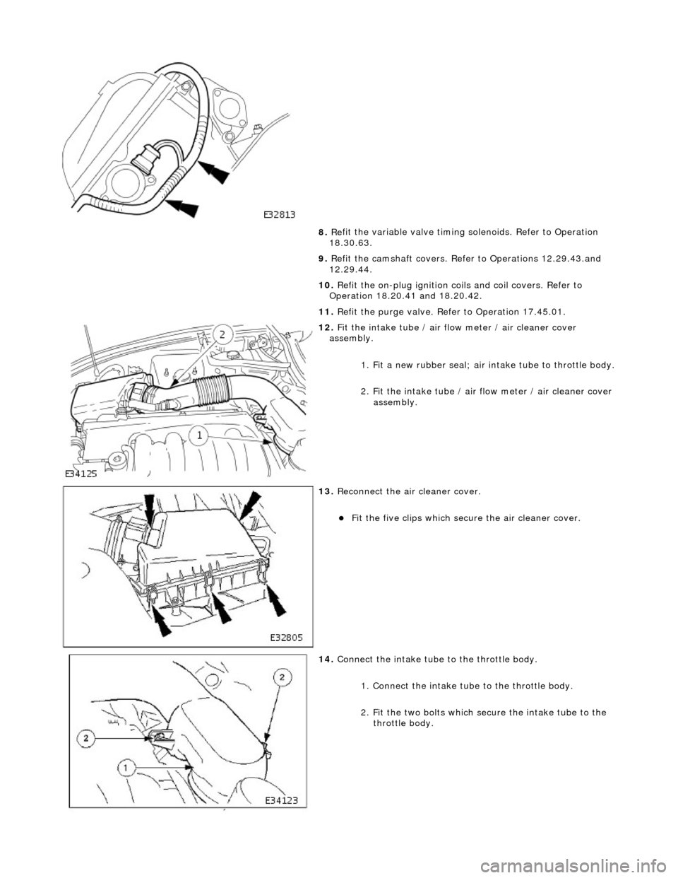
12 . F
it the intake tube / air flow meter / air cleaner cover
assembly.
1. Fit a new rubber seal; air in take tube to throttle body.
2.
Fit the intake tube / air
flow meter / air cleaner cover
assembly.
13 . R
econnect the air cleaner cover.
F
it
the five clips which secu
re the air cleaner cover.
14. Co
nnect the intake tube to the throttle body.
1. Connect the intake tube to the throttle body.
2. Fit the two bolts which secure the intake tube to the throttle body.
Page 653 of 2490
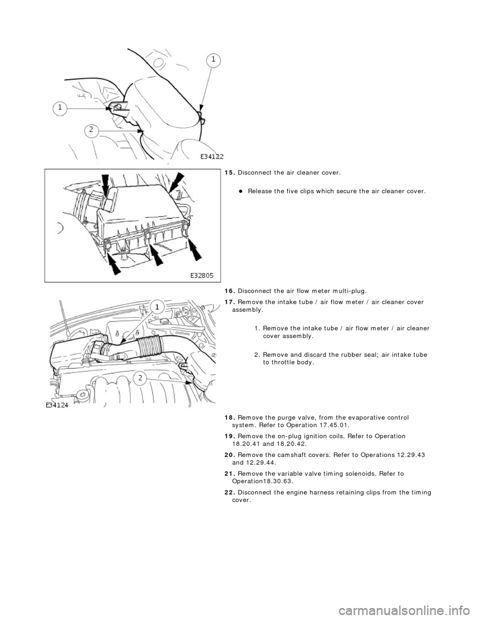
15
.
Disconnect the air cleaner cover.
R
elease the five clips which se
cure the air cleaner cover.
16. Disconnect the air flow meter multi-plug.
17
.
Remove the intake tube / air flow meter / air cleaner cover
assembly.
1. Remove the intake tube / air flow meter / air cleaner
cover assembly.
2. Remove and discard the ru bber seal; air intake tube
to throttle body.
18. Remove the purge valve, fro m the evaporative control
system. Refer to Operation 17.45.01.
19. Remove the on-plug ignition coils. Refer to Operation
18.20.41 and 18.20.42.
20. Remove the camshaft covers. Refer to Operations 12.29.43
and 12.29.44.
21. Remove the variable valve ti ming solenoids. Refer to
Operation18.30.63.
22. Disconnect the engine harness retaining clips from the timing
cover.
Page 657 of 2490
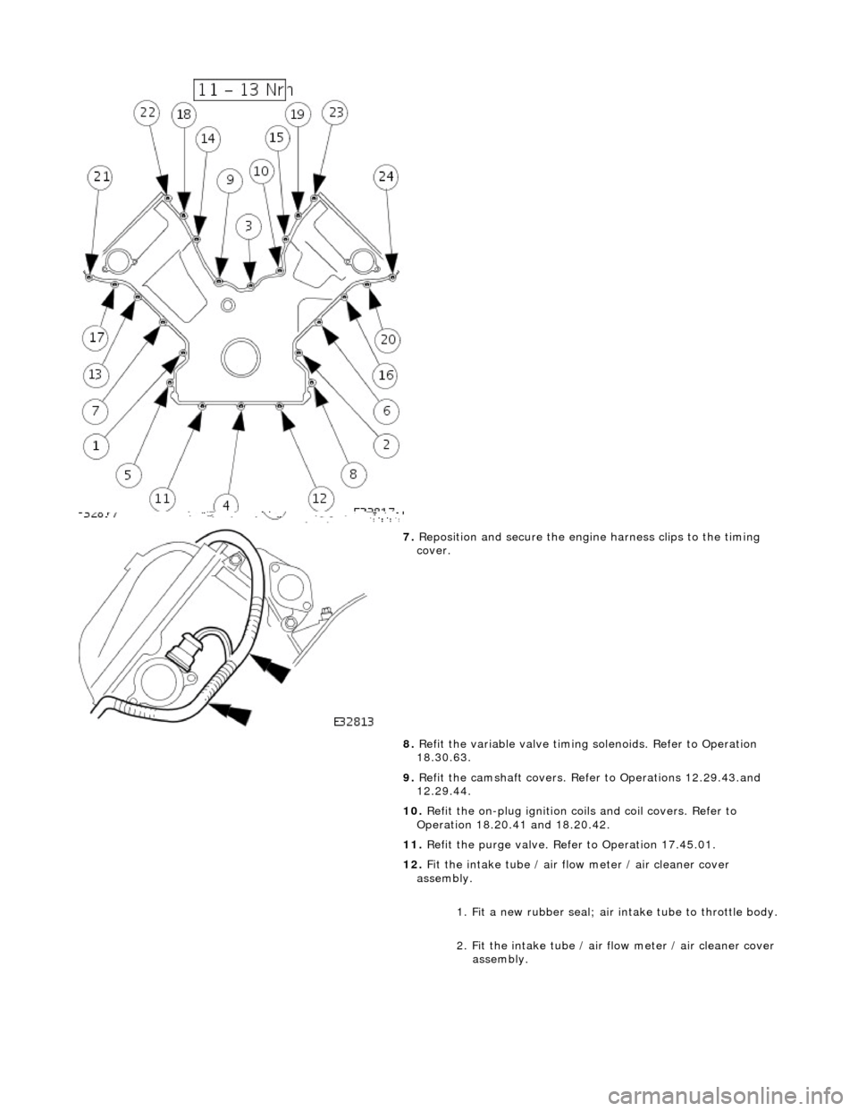
7. Reposition and secure the engine harness clips to the timing
cover.
8. Refit the variable valve timing solenoids. Refer to Operation
18.30.63.
9. Refit the camshaft covers. Refer to Operations 12.29.43.and
12.29.44.
10. Refit the on-plug ignition coils and coil covers. Refer to
Operation 18.20.41 and 18.20.42.
11. Refit the purge valve. Refer to Operation 17.45.01.
12. Fit the intake tube / air flow meter / air cleaner cover
assembly.
1. Fit a new rubber seal; air in take tube to throttle body.
2. Fit the intake tube / air flow meter / air cleaner cover
assembly.
Page 859 of 2490
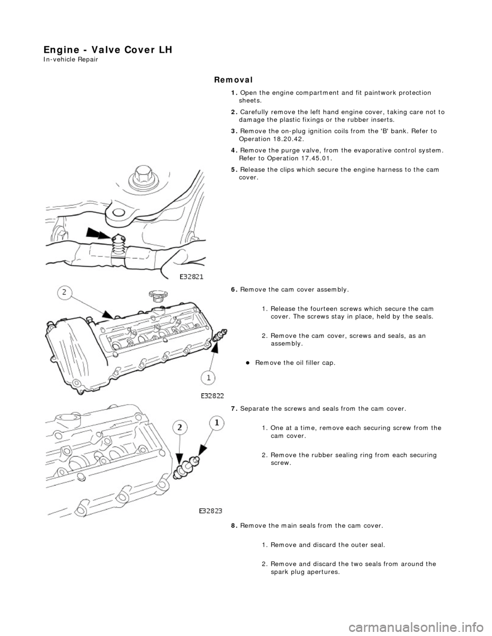
Engine - Valve Cover LH
In-vehicle Repair
Removal
1. Open the engine compartment and fit paintwork protection
sheets.
2. Carefully remove the le ft hand engine cover, taking care not to
damage the plasti c fixings or the rubber inserts.
3. Remove the on-plug ignition coils from the 'B' bank. Refer to
Operation 18.20.42.
4. Remove the purge valve, from th e evaporative control system.
Refer to Operation 17.45.01.
5. Release the clips which secure the engine harness to the cam
cover.
6. Remove the cam cover assembly.
1. Release the fourteen sc rews which secure the cam
cover. The screws stay in place, held by the seals.
2. Remove the cam cover, screws and seals, as an
assembly.
Remove the oil filler cap.
7. Separate the screws and se als from the cam cover.
1. One at a time, remove ea ch securing screw from the
cam cover.
2. Remove the rubber sealin g ring from each securing
screw.
8. Remove the main seals from the cam cover.
1. Remove and discard the outer seal.
2. Remove and discard the two seals from around the spark plug apertures.