radio JAGUAR X308 1998 2.G Workshop Manual
[x] Cancel search | Manufacturer: JAGUAR, Model Year: 1998, Model line: X308, Model: JAGUAR X308 1998 2.GPages: 2490, PDF Size: 69.81 MB
Page 431 of 2490
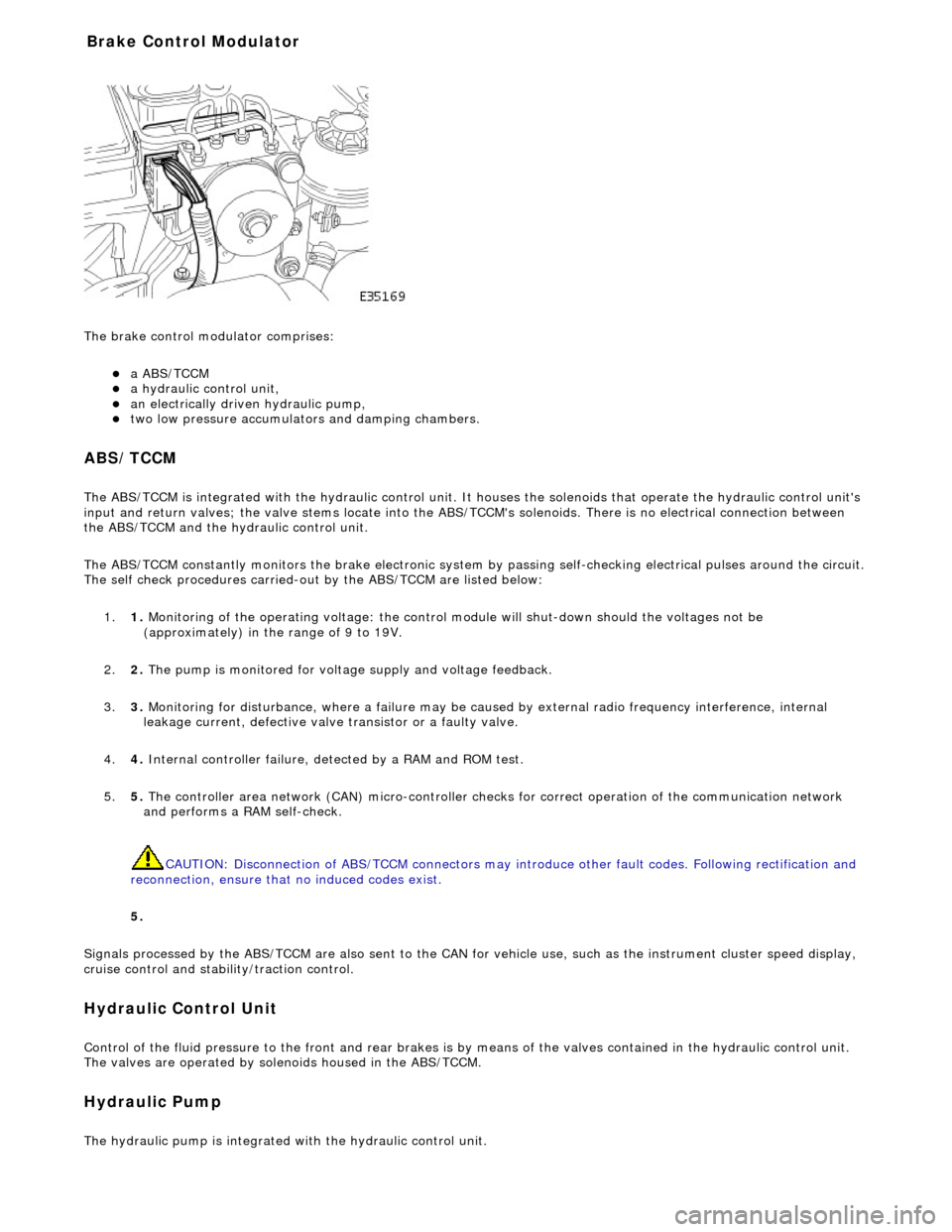
The brake
control modulator comprises:
a A
BS/TCCM
a h
ydraulic control unit,
an electrically driven hydrau
lic pump,
two low pressure accumulato
rs and damping chambers.
ABS/TCCM
The AB
S/TCCM is integrated with the hydrau
lic control unit. It houses the solenoids that operate the hydraulic control unit's
input and return valves; the valve stems locate into the ABS/TCCM's solenoids. There is no electrical connection between
the ABS/TCCM and the hydraulic control unit.
The ABS/TCCM constantly monitors the brake electronic system by passing self-checking electrical pulses around the circuit.
The self check procedures carried-out by the ABS/TCCM are listed below:
1. 1. Monitoring of the operating voltage: the control mo dule will shut-down should the voltages not be
(approximately) in the range of 9 to 19V.
2. 2. The pump is monitored for volt age supply and voltage feedback.
3. 3. Monitoring for disturbance, where a failure may be caus ed by external radio frequency interference, internal
leakage current, defective valve transistor or a faulty valve.
4. 4. Internal controller failure, de tected by a RAM and ROM test.
5. 5. The controller area network (CAN) micr o-controller checks for correct operation of the communication network
and performs a RAM self-check.
CAUTION: Disconnection of ABS/TCCM connectors may introduce other fault codes. Following rectification and
reconnection, ensure that no induced codes exist.
5.
Signals processed by the ABS/TCCM are also sent to the CAN for vehicle use, such as the instrument cluster speed display,
cruise control and stability/traction control.
Hydraulic Control Unit
Control of
the fluid pressure to
the front and rear brakes is by means of the valves contained in the hydraulic control unit.
The valves are operated by solenoids housed in the ABS/TCCM.
Hydraulic Pump
The
hydraulic pump is integrated
with the hydraulic control unit.
Bra
ke Control Modulator
Page 506 of 2490
2.2. Press and rel e
ase to cycle through radio FM, radio AM,
tape cassette, or CD player. Press and hold for two
seconds to select telephone mode.
3. 3. Decrease the volume of the select ed audio output or telephone.
4. 4. Press and release to select the next pr eset radio station, or the next track on tape or CD. Press and hold for two
seconds to select the next radio station on the waveband upwards, or the next CD loaded in the player, or to
change the side of tape. When in te lephone mode, press and release to scroll up to the next memory location.
Press and hold for two seconds to send and end a call.
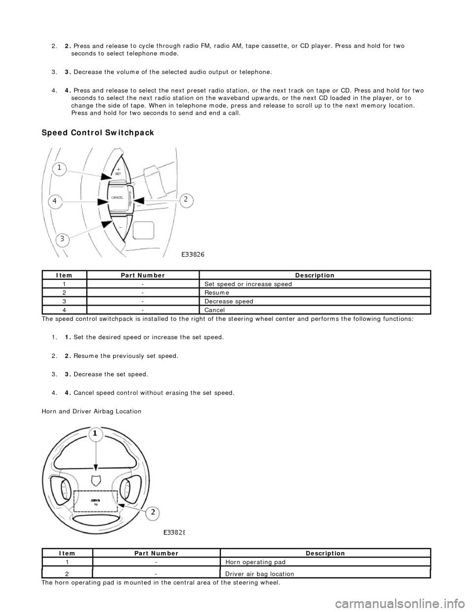
Speed Control Switchpa ck
The s p
eed control switchpack is installed to the right of th
e steering wheel center and performs the following functions:
1. 1. Set the desired speed or increase the set speed.
2. 2. Resume the previously set speed.
3. 3. Decrease the set speed.
4. 4. Cancel speed control without erasing the set speed.
Horn and Driver Airbag Location
Ite
m
Par
t
Number
De
scr
iption
1-Se
t
speed or increase speed
2-Re
sum
e
3-De
creas
e speed
4-Cancel
Ite
m
Part
Number
Descr
iption
1-Horn operatin
g pad
The ho
rn operating pad is mounted in the central area of the steering wheel.
2-Driver air bag location
Page 515 of 2490
Steering Column Switches - Steering Column Switches
Description an
d Operation
Ig
nition Switch
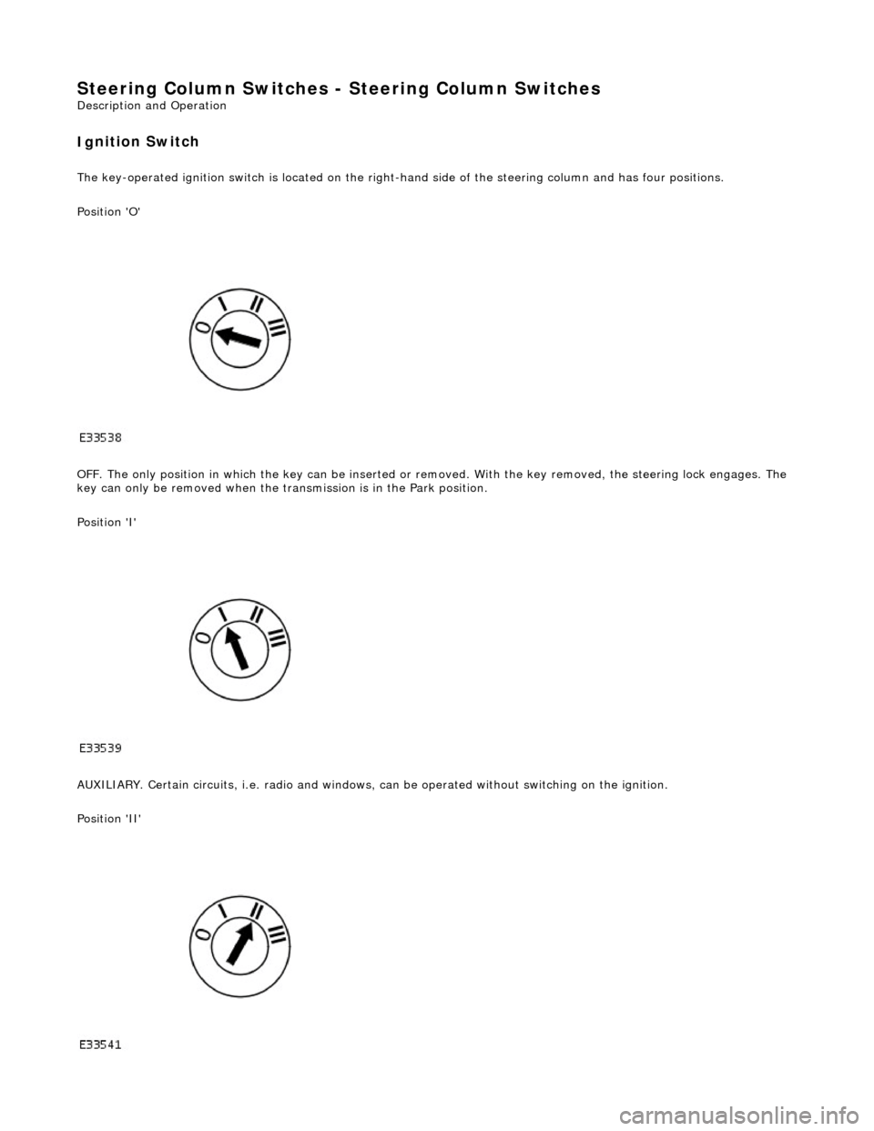
The k
ey-operated ignition switch is located on the right-hand side of the steering colu
mn and has four positions.
Position 'O'
OFF. The only position in which the key can be inserted or re moved. With the key removed, the steering lock engages. The
key can only be removed when the tran smission is in the Park position.
Position 'I'
AUXILIARY. Certain circuits , i.e. radio and windows, can be operat ed without switching on the ignition.
Position 'II'
Page 717 of 2490
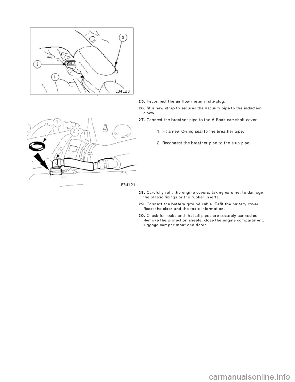
25. Reconnect the air flow meter multi-plug.
26. fit a new strap to secures the vacuum pipe to the induction
elbow.
27. Connect the breather pipe to the A-Bank camshaft cover.
1. Fit a new O-ring seal to the breather pipe.
2. Reconnect the breather pipe to the stub pipe.
28. Carefully refit the engine covers, taking care not to damage
the plastic fixings or the rubber inserts.
29. Connect the battery ground cabl e. Refit the battery cover.
Reset the clock and the radio information.
30. Check for leaks and that all pi pes are securely connected.
Remove the protection sheets, close the engine compartment,
luggage compartment and doors.
Page 728 of 2490
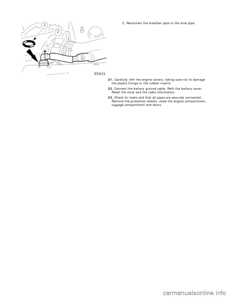
2. Reconnect the breather pipe to the stub pipe.
21. Carefully refit the engine covers, taking care not to damage
the plastic fixings or the rubber inserts.
22. Connect the battery ground cabl e. Refit the battery cover.
Reset the clock and the radio information.
23. Check for leaks and that all pi pes are securely connected.
Remove the protection sheets, close the engine compartment,
luggage compartment and doors.
Page 923 of 2490
be 'hun
g up' within the engine because it is not up to operating
temperature.
Should the oil level subsequently be topped-up, the level could
become too high, causing oil burning.
Typically, 0.875L is hung up.
Refill the engine with the correct specification engine oil.
58. Refill the automatic transmission. Refer to Section 307-01A,
Operation 44.24. 02.
59. Refill and bleed the power stee ring system. Refer to Section
211-02 General Procedures.
60. Repressurise the air conditioni ng system. Refer to Operation
82.30.30 and note all Wa rnings and Cautions.
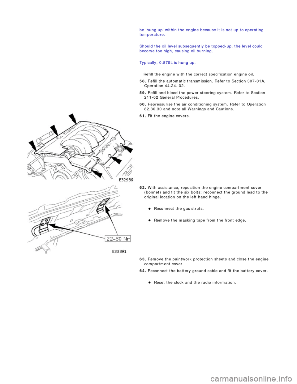
61
.
Fit the engine covers.
62
.
With assistance, reposition the engine compartment cover
(bonnet) and fit the si x bolts; reconnect the ground lead to the
original location on the left hand hinge.
Re
connect the gas struts.
R
emove the masking tape from the front edge.
63. Remove the paintwork protection sheets and close the engine
compartment cover.
64. Reconnect the battery ground cable and fit the battery cover.
Re
set the clock and the radio information.
Page 969 of 2490
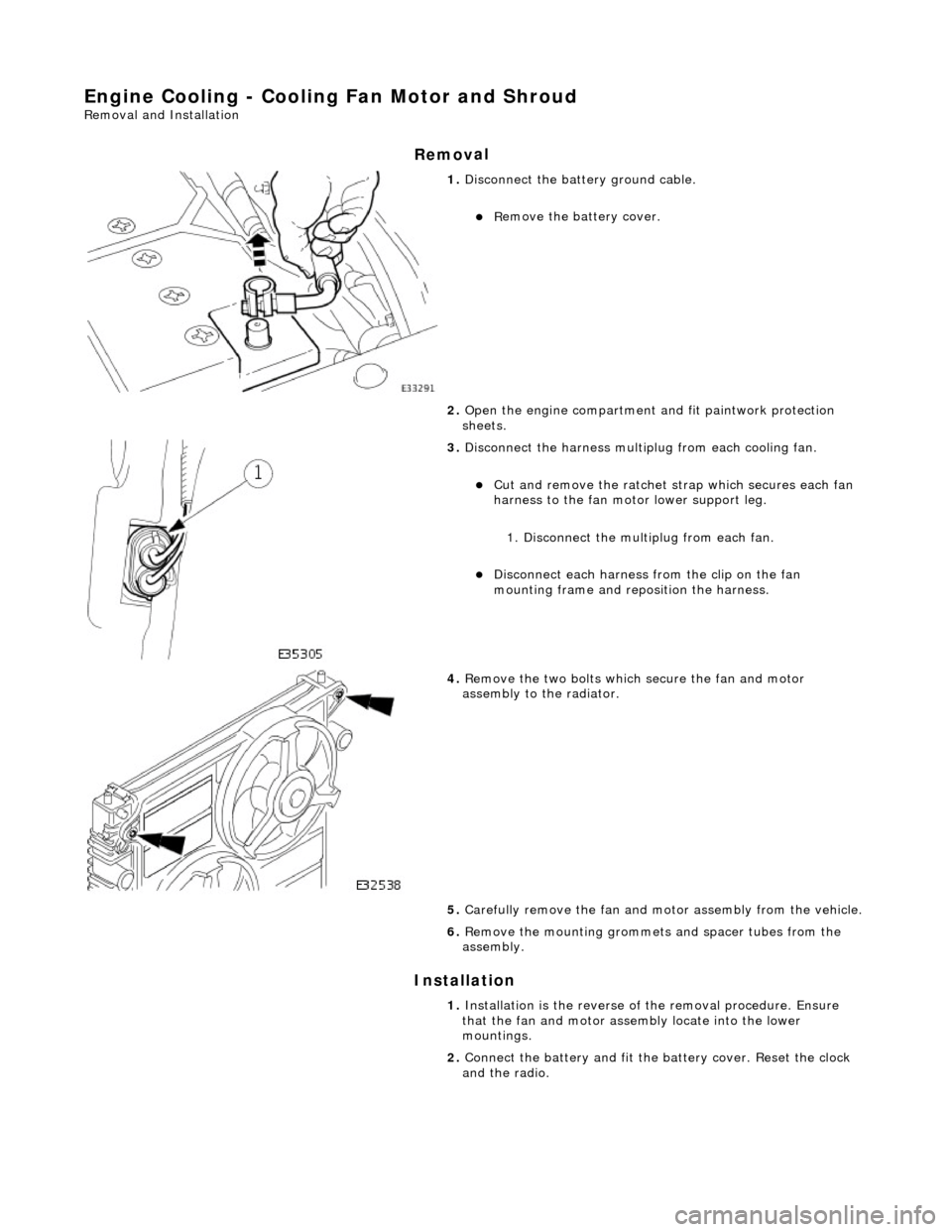
Engine Cooling - Cooling Fan Motor and Shroud
Re
moval and Installation
Remov
al
Installation
1.
Di
sconnect the batt
ery ground cable.
R
emove the battery cover.
2. Open the engine compartment and fit paintwork protection
sheets.
3. Disc
onnect the harness multip
lug from each cooling fan.
Cut an
d remove the ratchet st
rap which secures each fan
harness to the fan moto r lower support leg.
1. Disconnect the mult iplug from each fan.
Di
sconnect each harness
from the clip on the fan
mounting frame and repo sition the harness.
4. R
emove the two bolts which
secure the fan and motor
assembly to the radiator.
5. Carefully remove the fan and mo tor assembly from the vehicle.
6. Re
move the mounting grommets
and spacer tubes from the
assembly.
1. Installation is the reverse of the remova l procedure. Ensure
that the fan and motor assembly locate into the lower
mountings.
2. Connect the battery and fit the battery cover. Reset the clock
and the radio.
Page 979 of 2490

16
.
Refill the cooling system. Refer to the Refill procedure in
General Procedures.
17. Repressurise the climate cont rol system. Refer to Section
412-03 Observe all safety warnin gs and precautions stated in
that section.
18. Close the engine compartment cover.
19. Connect the battery and fit the battery cover. Reset the clock
and the radio.
Page 986 of 2490

16
. Re
fill the cooling system. Refer to the Refill procedure in
General Procedures.
17. Repressurise the climate cont rol system. Refer to Section
412-03 Observe all safety warnin gs and precautions stated in
that section.
18. Close the engine compartment cover.
19. Connect the battery and fit the battery cover. Reset the clock
and the radio.
Page 1071 of 2490
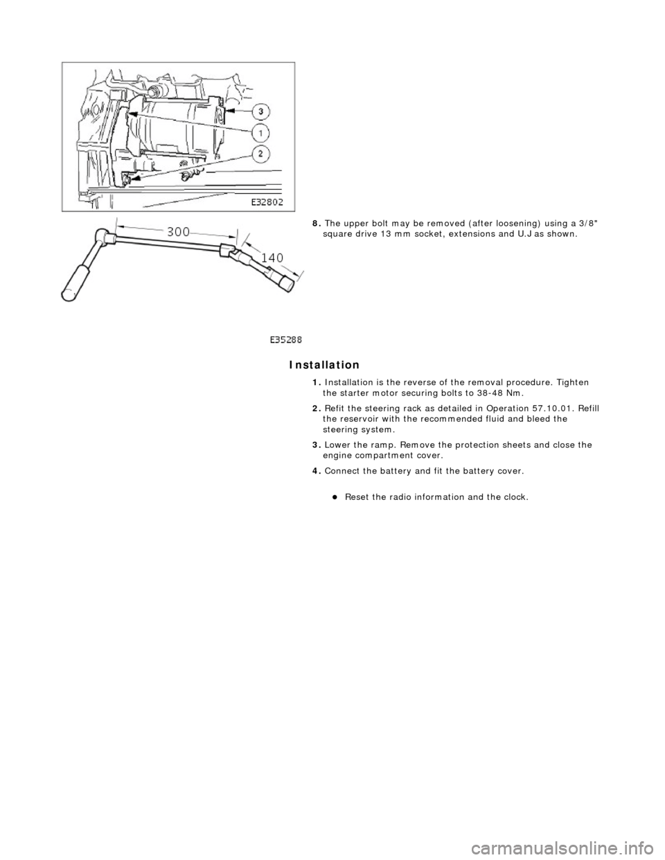
I
nstallation
8.
The u
pper bolt may be removed (a
fter loosening) using a 3/8"
square drive 13 mm socket, ex tensions and U.J as shown.
1. Installation is the reverse of the removal procedure. Tighten
the starter motor securing bolts to 38-48 Nm.
2. Refit the steering rack as detail ed in Operation 57.10.01. Refill
the reservoir with the reco mmended fluid and bleed the
steering system.
3. Lower the ramp. Remove the protection sheets and close the
engine compartment cover.
4. Connect the battery and fit the battery cover.
R
eset the radio informat
ion and the clock.
Page 2
of 2