driveshaft JAGUAR X308 1998 2.G Workshop Manual
[x] Cancel search | Manufacturer: JAGUAR, Model Year: 1998, Model line: X308, Model: JAGUAR X308 1998 2.GPages: 2490, PDF Size: 69.81 MB
Page 4 of 2490
Stabilizer Bar Mount i
ng
Frame (64.25.12)
Stabilizer Bar Mounting Frame Bushing (64.25.13)
Rear Wheel Bearing (64.15.14)
Wheel Hub Seal (64.15.15)
Wheel Knuckle Bushing (64.15.24)
204‐04: Wheels and Tires
Specification
Description and Operation
Wheels and Tires
Diagnosis and Testing
Wheels and Tires
Removal and Installation
Whee
l and Tire (74.20.05)
204‐05: Vehicle Dynamic Suspension
Description and Operation
Vehicle Dynamic Suspension
Diagnosis and Testing
Vehicle Dynamic Suspension
205: Driveline
205‐00: Driveline System ‐ General Information
Description and Operation
Driveline System
205‐01: Driveshaft
Specification
Description and Operation
Drives
haft
Removal and Installation
Driveshaft (47.15.01)
205‐02: Rear Drive Axle/Differential
Specification
Description and Operation
Page 280 of 2490
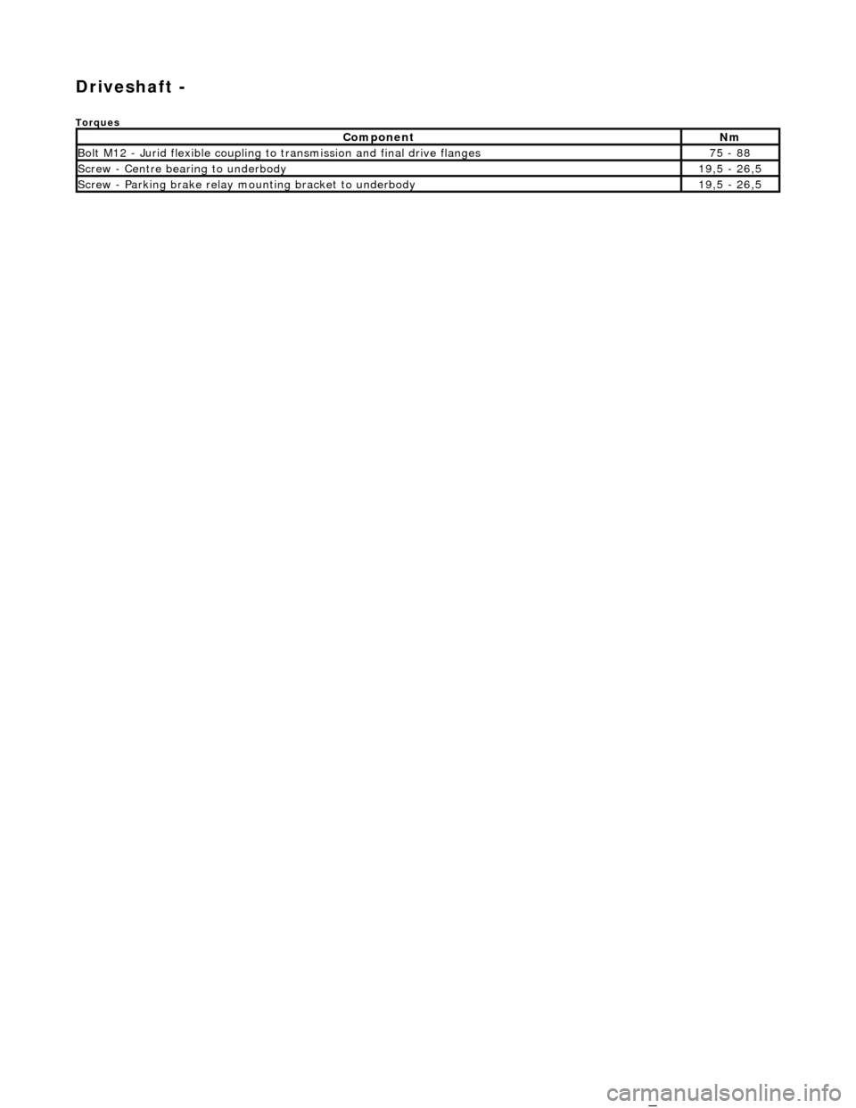
Driveshaft -
Torques
Comp
onent
Nm
Bol
t
M12 - Jurid flexible coupling to
transmission and final drive flanges
75
-
88
Screw
-
Centre bearing to underbody
19
,5
- 26,5
Screw
-
Parking brake relay mounting bracket to underbody
19
,5
- 26,5_
Page 281 of 2490

Driveshaft - Driveshaft
Description an
d Operation
Driveshaft Joint and Couplings
Parts List
It
em
Par
t Number
De
scription
1—F
lexible (Jurid) coupling at the transmission flange
2—Center bear
ing
3—Front tu
be, including
deformable section
4—Fl
exible (Jurid) coupling at the final drive flange
Page 282 of 2490
Driveshaft - Driveshaft
Remo
val and Installation
Remov
a
l
CAUTI
O
N: To preserve 'drive line' refine
ment, individual parts, other than fixings, MUST NOT be renewed. In the event
of any balance or driveshaft component related problem, the complete assembly must be renewed. Under no circumstances
may the flexible (Jurid) coupling be remo ved from the driveshaft (or its fixings be loosened). Do not drop or subject the
driveshaft to damage.
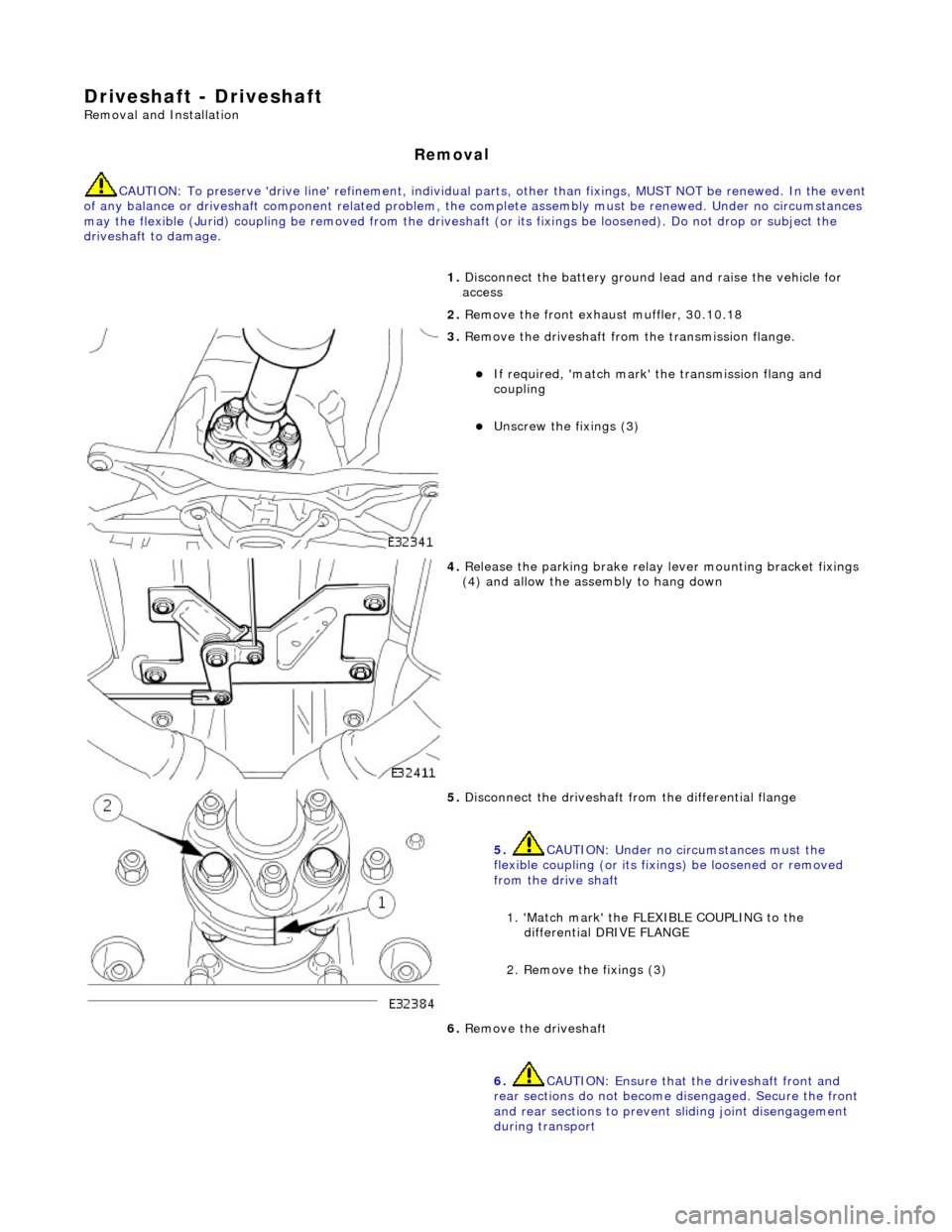
1. Disc
onnect the battery ground
lead and raise the vehicle for
access
2. Remove the front exha ust muffler, 30.10.18
3. Re
move the driveshaft from
the transmission flange.
If required, 'match mark'
the transmissi on flang and
coupling
Unscrew the fi xings (3)
4. Relea s
e the parking brake relay
lever mounting bracket fixings
(4) and allow the assembly to hang down
5. Disc onne
ct the driveshaft fr
om the differential flange
5. CAUTION: Under no circumstances must the
flexible coupling (or its fixings) be loosened or removed
from the drive shaft
1. 'Match mark' the FLEX IBLE COUPLING to the
differential DRIVE FLANGE
2. Remove the fixings (3)
6. Re
move the driveshaft
6. CAUTION: Ensure that the driveshaft front and
rear sections do not become disengaged. Secure the front
and rear sections to preven t sliding joint disengagement
during transport
Page 283 of 2490
I
nstallation
•
NOTE: The large diameter driveshaft tu
be MUST be towards the transmission
R
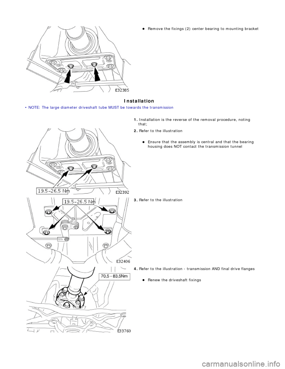
emove the fixings (2) center
bearing to mounting bracket
1. Installation is the reverse of the removal procedure, noting
that;
2. R
efer to the illustration
E
nsure that the asse
mbly is central and that the bearing
housing does NOT contact the transmission tunnel
3. R
efer to the illustration
4. R
efer to the illustration - tran
smission AND final drive flanges
R
enew the driveshaft fixings
Page 285 of 2490
R
ear Drive Axle/Differential - Rear Drive Axle and Differential
Description an
d Operation
Loca
tion
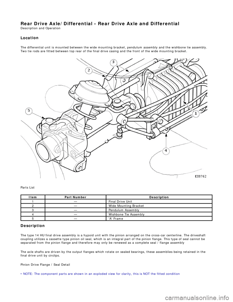
The differential
unit
is mounted between the wide mount ing bracket, pendulum assembly and the wishbone tie assembly.
Two tie rods are fitted between top rear of the final dr ive casing and the front of the wide mounting bracket.
Parts List
Description
The
type 14 HU final drive assembly is a hypoid unit with th
e pinion arranged on the cross-car centerline. The driveshaft
coupling utilizes a cassette type pinion oil seal, which is an in tegral part of the pinion flange. This type of seal cannot be
separated from the pinion fl ange and therefore may only be renewed as a complete seal / flange assembly
The axle shafts are driven by the output flanges which rotate on sealed bearings , these assemblies being retained in the
final drive unit by circlips.
Pinion Drive Flange / Seal Detail
• NOTE: The component parts are shown in an exploded view for clarity, this is NOT the fitted condition
It
em
Par
t Number
De
scription
1—F
inal Drive Unit
2—W
ide Mounting Bracket
3—Pen
dulum Assembly
4—Wi
shbone Tie Assembly
5—'A'
Frame
Page 289 of 2490

carri
er
7. Protect
the driveshaft thread wi
th special tool JD 1D / 7.
8. Wi
thdraw the hub from the axle shaft
8. CAUTION: Take care not to introduce debris into
the hub bearings, or damage the seal
U
sing service tool 204 - 011,
push the axle shaft through
the hub
9. NO
TE: In the wheel-free condition, the axle is in tension and
the flanges will separate as the nuts are withdrawn
Release the axle shaft 1. Remove and discard the (4) nuts axle shaft to differential output shaft
2. Clear the axle shaft from the output flange studs
3. Remove and keep safe the camber shim
10. NOTE: The axle shaft nuts may damage the studs upon
removal; check the thread conditio n by engaging a new nut 2 or 3
threads by hand.
Inspect the output flange studs and renew if there is evidence
of damage / distortion
11. Clean all traces of thread lo cking agent from the hub splines
Page 296 of 2490
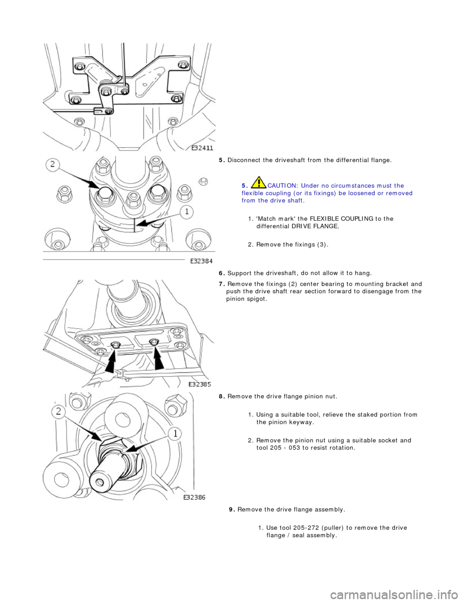
5. Disconne
ct the driveshaft fr
om the differential flange.
5. CAUTION: Under no circumstances must the
flexible coupling (or its fixings) be loosened or removed
from the drive shaft.
1. 'Match mark' the FLEX IBLE COUPLING to the
differential DRIVE FLANGE.
2. Remove the fixings (3).
6. Support the d
riveshaft, do not allow it to hang.
7. Re
move the fixings (2) center
bearing to mounting bracket and
push the drive shaft rear sectio n forward to disengage from the
pinion spigot.
8. Remove the drive flange pinion nu
t.
1. Using a suitable tool, re lieve the staked portion from
the pinion keyway.
2. Remove the pinion nut using a suitable socket and tool 205 - 053 to resist rotation.
9. Remove the drive flange assembly.
1. Use tool 205-272 (puller) to remove the drive flange / seal assembly.
Page 298 of 2490

7. Chec k
that the pinion sp
igot radial run-out.
0,08
mm MAX TIR.
If t
hi
s specification is exceeded, contact Jaguar Service.
8. Re
fer to the illustration.
R
e
new the driveshaft fixings.
9. Re
fer to the illustration.
E
n
sure that the bear
ing is central.
10. Refer to the illustration.
Page 905 of 2490

Remove the bolts which secure the downpipe to the lower
mounting bracket.
Remove the downpipe assembly.
Repeat the above operations for the other downpipe
catalytic converter.
47. Remove the two bolts which secure each mounting bracket to
the bell housing and remove the brackets.
48. Disconnect the driveshaft (propshaft) flange from the
transmission output flange.
Remove the three bolts which secure the flange. Rotate
the shaft for access to each bolt.
Disconnect the shaft and reposition it to the side.
49. Remove the securing bolt and disconnect the ground lead
from the transmission casing.
50. Disconnect the oil cooler pi pes (where fitted) from the
engine.
1. Remove the bolt which secures the pipe clamping
plate. Remove the clamping plate.
2. Place a drain tray beneat h the pipes and disconnect