JAGUAR X308 1998 2.G Workshop Manual
X308 1998 2.G
JAGUAR
JAGUAR
https://www.carmanualsonline.info/img/21/7640/w960_7640-0.png
JAGUAR X308 1998 2.G Workshop Manual
Page 211 of 2490
4
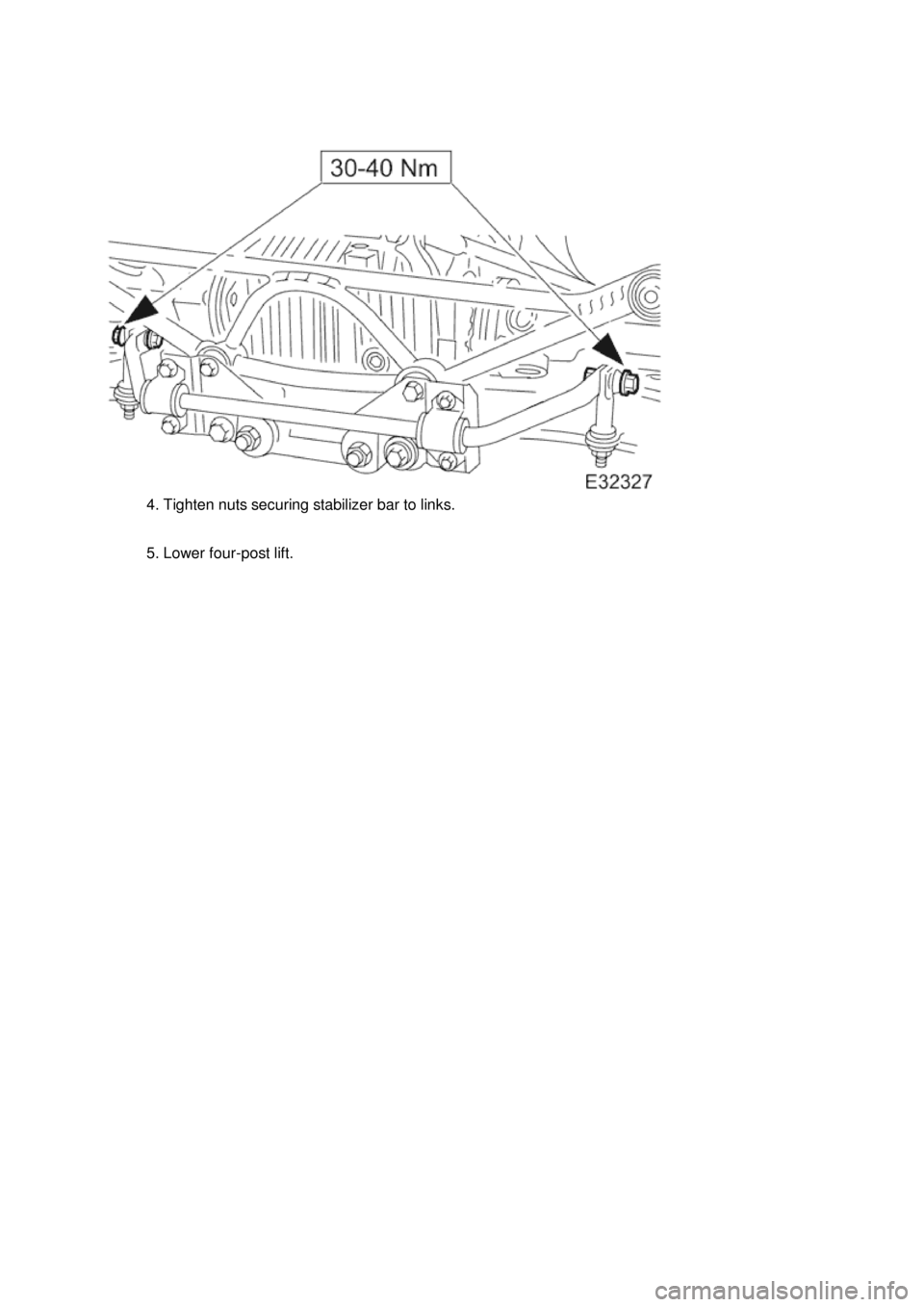
. Tighten nuts securing stabilizer bar to links.
5. Lower four-post lift.
Page 217 of 2490
4
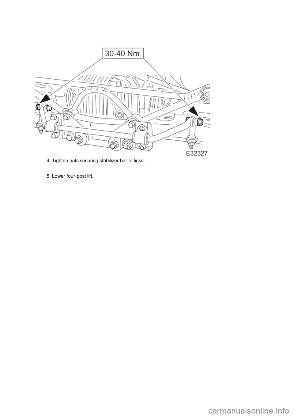
. Tighten nuts securing stabilizer bar to links.
5. Lower four-post lift.
Page 222 of 2490
Remova
l
2
05-2
34 (JD 550-1)
1. CAUTION: Replacement of nuts and bolts: Various
thread-locking devices are used on nuts and bolts throughout the
vehicle. These devices restrict the number of times a nut or bolt
can be used. See section 100-00 for information.
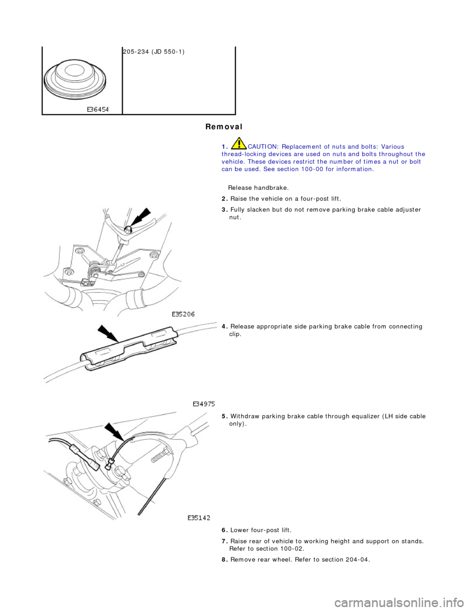
Release handbrake.
2. Ra
ise the vehicle on a four-post lift.
3. Fully slacken bu
t do not remove parking brake cable adjuster
nut.
4. Relea s
e appropriate side parkin
g brake cable from connecting
clip.
5. With draw parkin
g brake cable th
rough equalizer (LH side cable
only).
6. Lower four-post lift.
7. Raise rear of vehicle to workin g height and support on stands.
Refer to section 100-02.
8. Remove rear wheel. Refer to section 204-04.
Page 235 of 2490
35
.
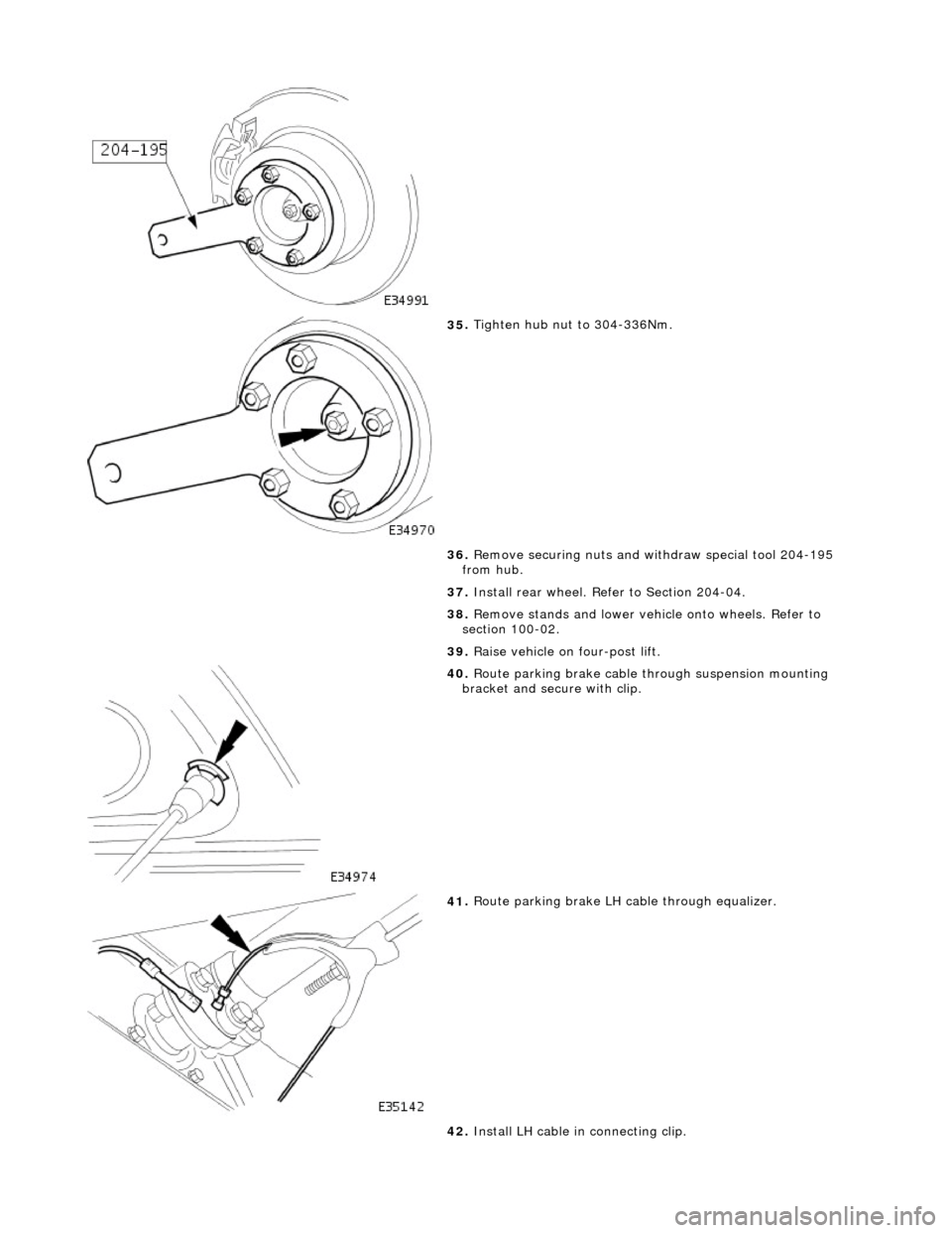
Tighten hub nut to 304-336Nm.
36. Remove securing nuts and withdraw special tool 204-195
from hub.
37. Install rear wheel. Refer to Section 204-04.
38. Remove stands and lower vehi cle onto wheels. Refer to
section 100-02.
39. Raise vehicle on four-post lift.
40
.
Route parking brake cable through suspension mounting
bracket and secure with clip.
41
.
Route parking brake LH ca ble through equalizer.
42. Install LH cable in connecting clip.
Page 236 of 2490
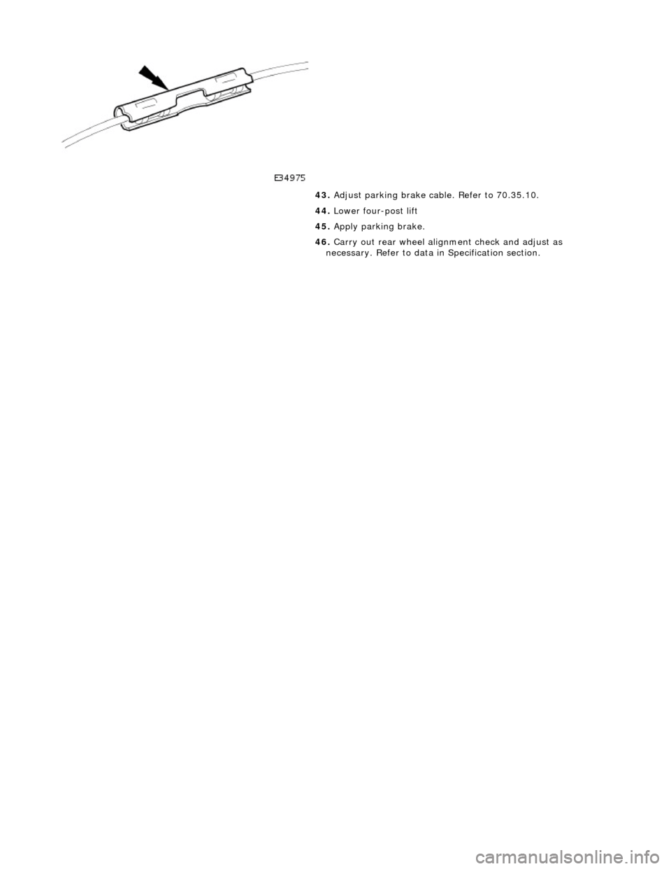
43
. Adjust parkin
g brake cable. Refer to 70.35.10.
44. Lower four-post lift
45. Apply parking brake.
46. Carry out rear wheel alignm ent check and adjust as
necessary. Refer to data in Specification section.
Page 238 of 2490
clip
.
5. With draw parkin
g brake cable th
rough equalizer (LH side cable
only).
6. Lower four-post lift.
7. Raise rear of vehicle to workin g height and support on stands.
Refer to section 100-02.
8. Remove rear wheel. Refer to section 204-04.
9. Posit i
on special tool (204-1
95) on hub studs and install
securing nuts.
10 . Slac
ken but do not remove hub to axle shaft securing nut.
11. Remove nuts and withdraw special tool (204-195) from hub.
12. Remove rear brake disc. Refer to 70.10.13.
13. Remove parking brake shoe s. Refer to 70.40.05.
14. Remove wheel speed sensor.
Page 247 of 2490
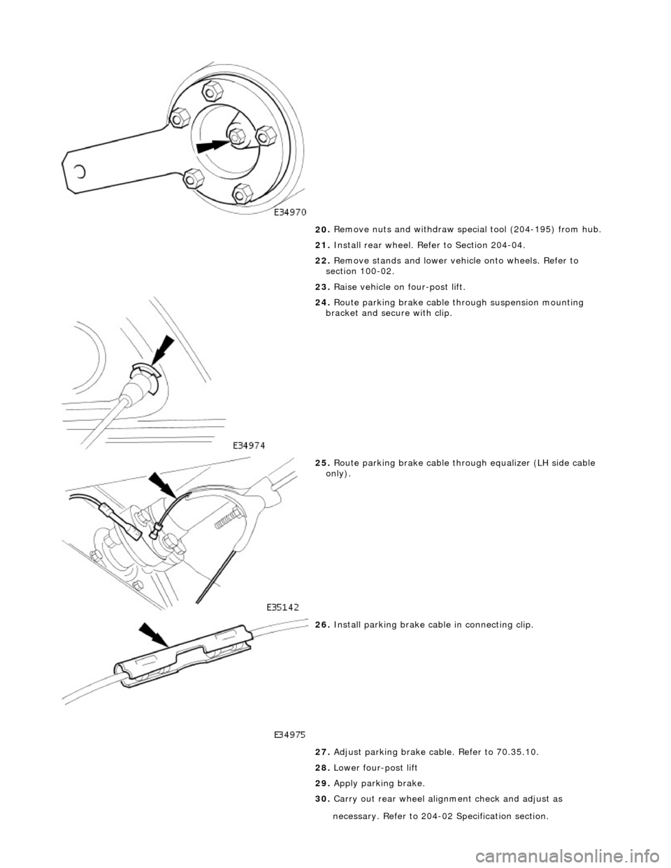
20
.
Remove nuts and withdraw special tool (204-195) from hub.
21. Install rear wheel. Refer to Section 204-04.
22. Remove stands and lower vehi cle onto wheels. Refer to
section 100-02.
23. Raise vehicle on four-post lift.
24
.
Route parking brake cable through suspension mounting
bracket and secure with clip.
25
.
Route parking brake cable through equalizer (LH side cable
only).
26
.
Install parking brake cabl e in connecting clip.
27. Adjust parking brake cable. Refer to 70.35.10.
28. Lower four-post lift
29. Apply parking brake.
30. Carry out rear wheel alignm ent check and adjust as
necessary. Refer
t
o 204-02 Specification section.
Page 249 of 2490
cli
p.
5. With
draw parking brake cable th
rough equalizer (LH side cable
only).
6. Lower four-post lift.
7. Raise rear of vehicle to workin g height and support on stands.
Refer to section 100-02.
8. Remove rear wheel. Refer to section 204-04.
9. Posit
ion special tool (204-1
95) on hub studs and install
securing nuts.
10
.
Slacken but do not remove hub to axle shaft securing nut.
11. Remove securing nuts from stud s and withdraw special tool
(204-195) from hub.
12. Remove rear brake disc. Refer to 70.10.13.
13. Remove parking brake shoe s. Refer to 70.40.05.
14. Remove wheel speed sensor.
Page 258 of 2490
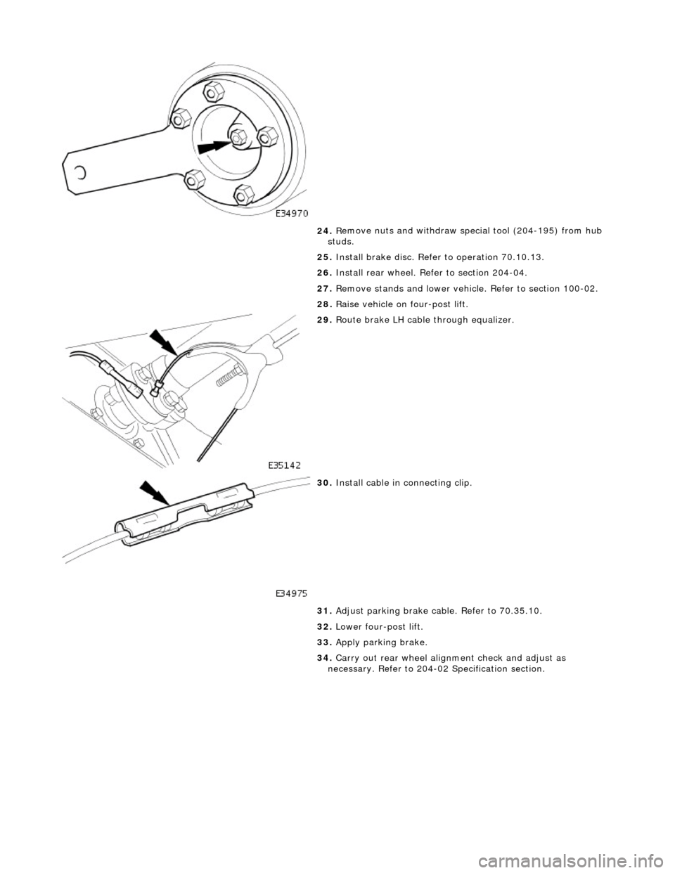
24
. R
emove nuts and withdraw special tool (204-195) from hub
studs.
25. Install brake disc. Refer to operation 70.10.13.
26. Install rear wheel. Refer to section 204-04.
27. Remove stands and lower vehicl e. Refer to section 100-02.
28. Raise vehicle on four-post lift.
29 . Rout
e brake LH cable through equalizer.
30 . Inst
all cable in connecting clip.
31. Adjust parking brake cable. Refer to 70.35.10.
32. Lower four-post lift.
33. Apply parking brake.
34. Carry out rear wheel alignm ent check and adjust as
necessary. Refer to 204-02 Specification section.
Page 1779 of 2490
Installation
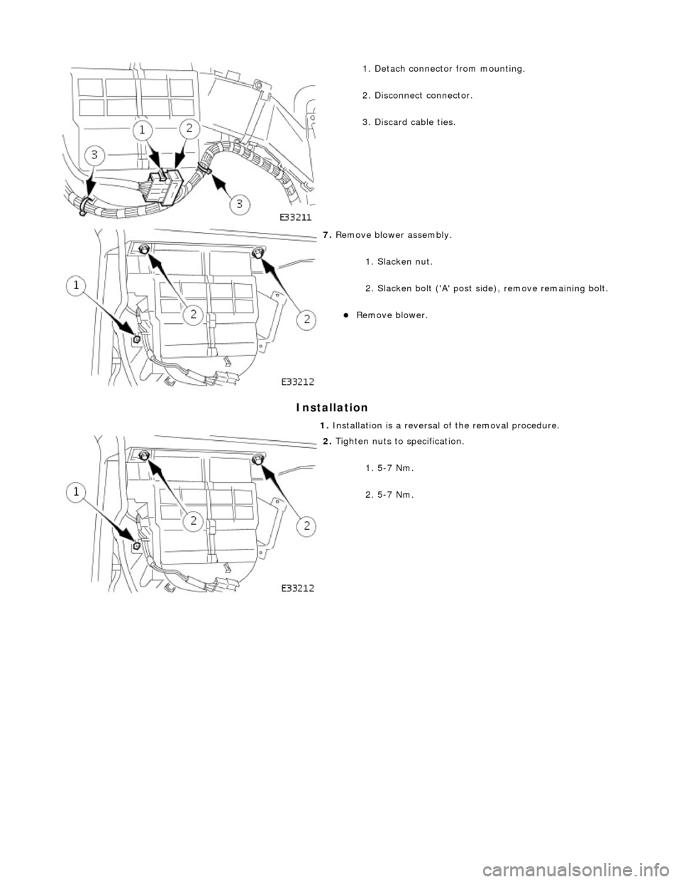
1. Detach connector from mounting.
2. Disconnect connector.
3. Discard cable ties.
7. Remove blower assembly.
1. Slacken nut.
2. Slacken bolt ('A' post si de), remove remaining bolt.
Remove blower.
1. Installation is a reversal of the removal procedure.
2. Tighten nuts to specification.
1. 5-7 Nm.
2. 5-7 Nm.