clock JAGUAR X308 1998 2.G Workshop Manual
[x] Cancel search | Manufacturer: JAGUAR, Model Year: 1998, Model line: X308, Model: JAGUAR X308 1998 2.GPages: 2490, PDF Size: 69.81 MB
Page 22 of 2490

Ambient Air Temperature Sensor (82.20. 02)
Cold Ai
r
Bypass Blend Door Actuator (82.20.86)
Defrost Vent/Register Blend Door Actuator (82.20.84)
Footwell Vent/Duct Blend Door Actuator (80.20.20 or 82.20.85)
Instrument Panel Blend Door Actuator (82.20.83)
Remote Climate Control Module LHD (82.20.65)
Remote Climate Control Module RHD (82.20.65)
413: Instrumentation and Warning Sy
stems
413‐00: Instrument Cluster and Panel Illumination
Description and Operation
Instrument Cluster and Panel Illumination
Removal and Installation
Instrument Panel Dimmer Switch (86.65.07)
413‐01: Instrument Cluster
Description and Operation
Instrument Cluster
Diagnosis and Testing
Instrument Cluster
Removal and Installation
Instrument Clust
er (88.20.01)
413‐06: Horn
Description and Operation
Horn
Diagnosis and Testing
Horn
413‐07: Clock
Description and Operation
Clock
Diagnosis and Testing
Clock
Removal and Installation
Clock (88.15.07)
Page 55 of 2490
P
arts List
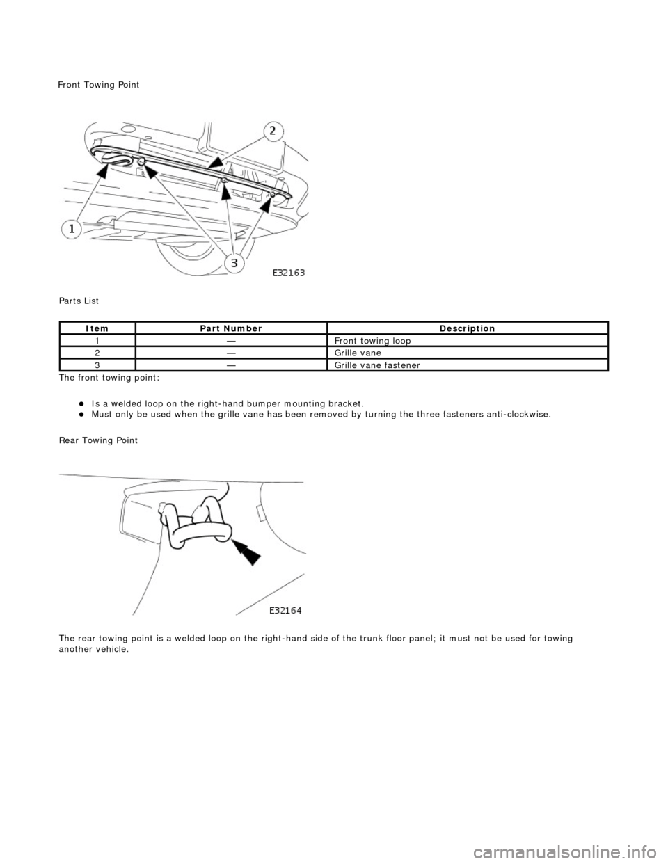
The front towing point:
Is a welded loop on the ri
ght-ha
nd bumper mounting bracket.
Mus
t only be used when the grille
vane has been removed by turning the three fasteners anti-clockwise.
Rear Towing Point
The rear towing point is a welded loop on the right-hand side of the trunk floor panel; it must not be used for towing
another vehicle.
It
em
Par
t Number
De
scription
1—Fr
ont towing loop
2—Gr
ille vane
3—Gr
ille vane fastener
F
ront Towing Point
Page 377 of 2490

Remove brake
pads from caliper housing.
Discard
brake pads.
7. R
emove caliper carrier from hub carrier.
Re
move bolts.
R
emove carrier.
8. Ali
gn brake disc access hole
with parking brake adjuster.
R
emove plug from access hole.
Rotate
brake disc until ac
cess hole is aligned with
adjuster.
9. Slacken parking brake adju
ster.
Rot
ate adjuster clockwise.
10. Remove brake disc from wheel studs.
Page 381 of 2490

6. CAUTI
ONS:
Only remove the bolts securi ng the caliper anchor bracket
to the hub carrier. Refer to caution above for more information.
Do not allow the caliper to hang on the hydraulic hose, as
this will damage the hose.
Remove caliper from hub carrier.
Re
move bolts.
Re
move and tie caliper aside.
7.
Ali
gn brake disc access hole
with parking brake adjuster.
R
emove plug from access hole.
Rotate
brake disc until ac
cess hole is aligned with
adjuster.
8. Slacken parking brake adju
ster to
allow for the removal of the
brake disc.
Rot
ate adjuster clockwise.
9. Remove brake disc from hub.
Page 394 of 2490
Parking Brake and Actuation - P
arking Brake Shoe
and Lining Adjustment
Gene
ral Procedures
1. Raise rear of vehicle and support on stands. See section 100-
02.
2. Remove both rear wheels.
3. Make sure that the parking br ake lever is in the released
position, and the gear selector lever is in neutral (N).
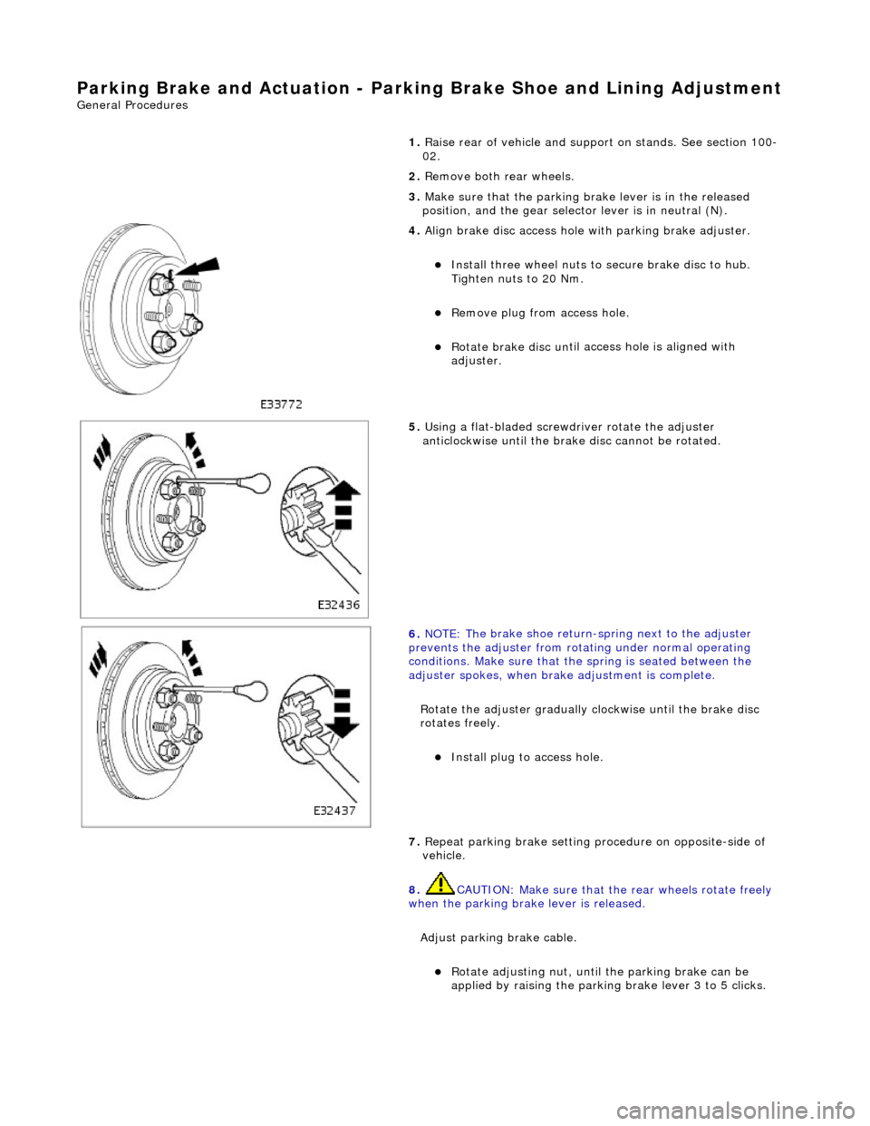
4. Alig
n brake disc access hole
with parking brake adjuster.
Instal
l three wheel nuts to secure brake disc to hub.
Tighten nuts to 20 Nm.
R e
move plug from access hole.
Rotate
brake disc un
til ac
cess hole is aligned with
adjuster.
5. Using a flat-bladed screwdriv er rotate the adjuster
anti
clockwise until the brake disc cannot be rotated.
6. NOTE : Th
e brake shoe return-spring next to the adjuster
prevents the adjuster from rota ting under normal operating
conditions. Make sure that the spring is seated between the
adjuster spokes, when brake adjustment is complete.
Rotate the adjuster gradually clockwise until the brake disc
rotates freely.
Inst al
l plug to access hole.
7. Repeat parking brake setting pr ocedure on opposite-side of
vehicle.
8. CAUTION: Make sure that th e rear wheels rotate freely
when the parking brake lever is released.
Adjust parking brake cable.
Ro
tate adjusting nut, until the parking brake can be
applied by raising the parking brake lever 3 to 5 clicks.
Page 518 of 2490
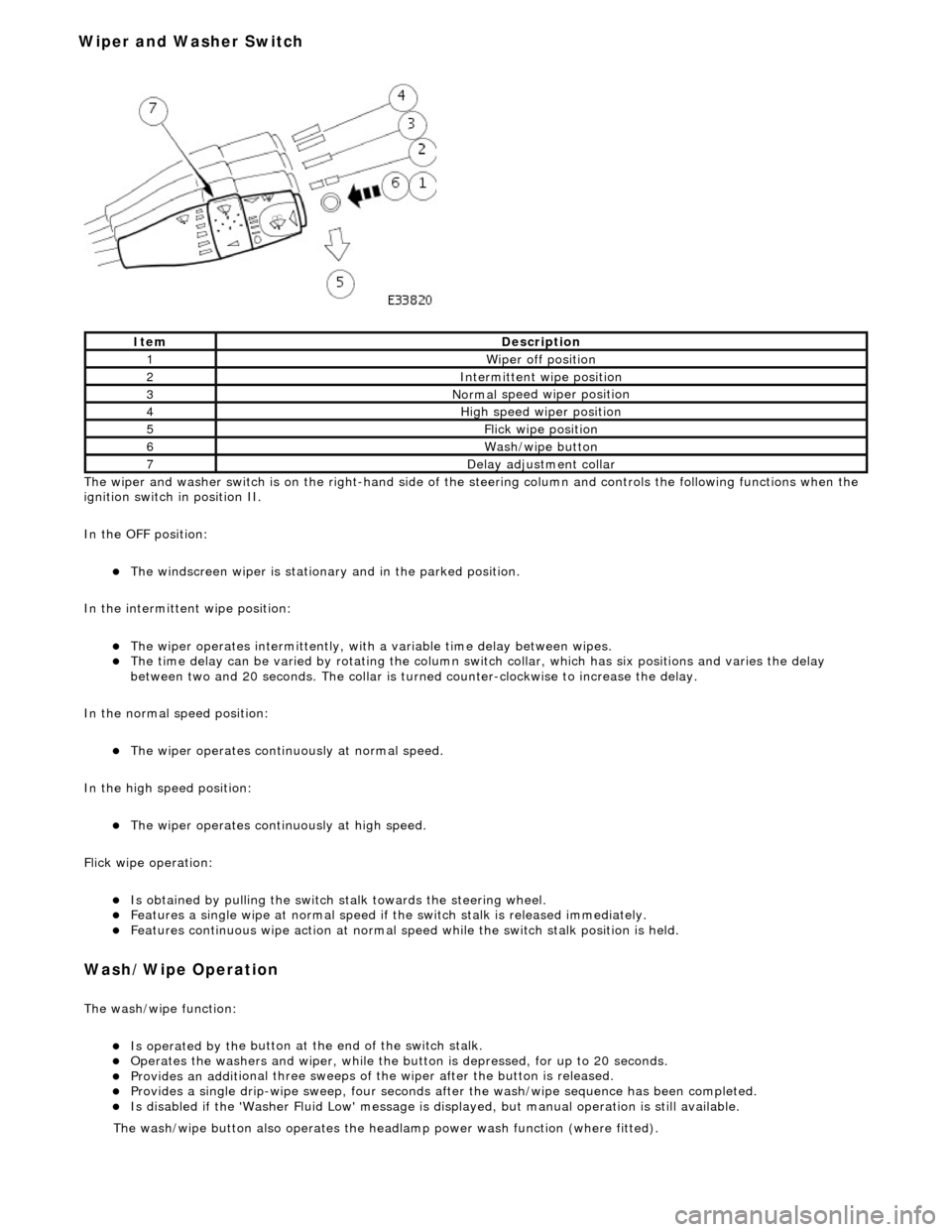
The wiper and washer switch i s
on the righ
t-hand side of the steering column and controls the fo llowing functions when the
ignition switch in position II.
In the OFF position:
The windscreen wiper is stationary and in the parked positio
n.
In the intermittent wipe position:
The wi per ope
rates intermittently, with
a variable time delay between wipes.
The time del
ay can be varied by rotating the column sw
itch collar, which has six positions and varies the delay
between two and 20 seconds. The collar is turned counter-clockwise to increase the delay.
In the normal speed position:
The wiper oper a
tes continuously at normal speed.
In the high speed position:
The wiper ope r
ates continuously at high speed.
Flick wipe operation:
Is obt
ained by pulling the switch
stalk towards the steering wheel.
F
e
atures a single wipe at normal speed if
the switch stalk is released immediately.
Fe
atures continuous wipe action
at normal speed while the swit ch stalk position is held.
Wash/W
ipe Operation
Th
e
wash/wipe function:
Is operat
ed by th
e button at the end of the switch stalk.
Op
erate
s the washers and wiper, while the butt
on is depressed, for up to 20 seconds.
Provides an addit
ional three sweeps of
the wiper after the button is released.
Provid
es a single drip-wipe sweep, four seconds af
ter the wash/wipe sequence has been completed.
Is disabled if the 'Washer Flu
id Low' message is di
splayed, but manual operat ion is still available.
Ite
m
De
scr
iption
1W
i
per off position
2Intermittent
wipe position
3Normal
speed wiper position
4High
speed wiper position
5Flick wipe position
6Wa
sh/wipe button
7D
e
lay adjustment collar
The was
h
/wipe button also operates the head
lamp power wash function (where fitted).
Wiper and Washer Switch
Page 572 of 2490

2. Fi
t the retaining / pivot bolt and tighten it to 12 - 16
Nm.
5. Refi
t the primary chain tensione
r assembly. Refer to Operation
12.65.55 in this Section.
U s
e a wedge 303 - 533 (or two if required) between the
primary chain tensioner and te nsioner blade, to take up
the slack in the chain.
6. Tigh te
n the exhaust camshaft
sprocket securing bolt.
1. Fit the chain tensioner tool 303 - 532 to the sprocket holes.
1. Apply force to the to
ol in
an anti-clockwise direction
to tension the chain on its drive side.
2 .
Whilst applying the opposing force to the sprocket
and chain, tighten the sprock et securing bolt to 115 -
125 Nm.
7. Tigh te
n the VVT unit securing bolt.
1. Whilst still applying the opposing force to the
sprocket and chain (using 303 - 532), check that the
wedges are still in place, tighten the VVT unit
securing bolt to 115 - 125 Nm.
Re
move the chain tensioning
tool and the wedge(s).
8. Remove the camshaft locking tool 303 - 530 and transfer it to
the A-Bank camshafts, aligning the shafts slightly as necessary.
Page 574 of 2490
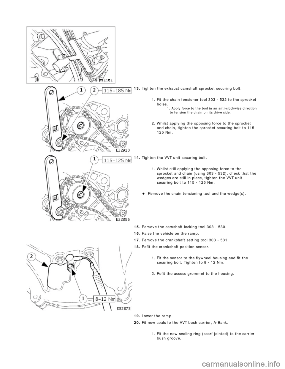
13. Tigh
ten the exhaust camshaft
sprocket securing bolt.
1. Fit the chain tensioner tool 303 - 532 to the sprocket holes.
1. Apply force to the to
ol in
an anti-clockwise direction
to tension the chain on its drive side.
2 .
Whilst applying the opposing force to the sprocket
and chain, tighten the sprock et securing bolt to 115 -
125 Nm.
14 . Tigh
ten the VVT unit securing bolt.
1. Whilst still applying the opposing force to the
sprocket and chain (using 303 - 532), check that the
wedges are still in place, tighten the VVT unit
securing bolt to 115 - 125 Nm.
R e
move the chain tensioning
tool and the wedge(s).
15. Remove the camshaft locking tool 303 - 530.
16. Raise the vehicle on the ramp.
17. Remove the crankshaft setting tool 303 - 531.
18 . R
efit the crankshaft position sensor.
1. Fit the sensor to the fl ywheel housing and fit the
securing bolt. Tighten to 8 - 12 Nm.
2. Refit the access grommet to the housing.
19. Lower the ramp.
20. Fit new seals to the VVT bush carrier, A-Bank.
1. Fit the new sealing ring ( scarf jointed) to the carrier
bush groove.
Page 582 of 2490

2.
Install the retaining / pivo
t bolt and tighten it to 12-
16 Nm.
5. Install the primary ch
ain te
nsioner assembly. Refer to
Operation 12.65.55.
Use a wedge 3 03-5
33 (or two if required) between the
primary chain tensioner and te nsioner blade, to take up
the slack in the chain.
6. Tigh te
n the exhaust camshaft
sprocket securing bolt.
1. Install the chain tensioner tool 303-532 to the sprocket holes.
Appl y force
to the tool in an
anti-clockwise direction to
tension the chain on its drive side.
2. Whilst applying the opposing force to the sprocket and chain, tighten the sprock et securing bolt to 115-
125 Nm.
7. Tigh te
n the intake camshaft
sprocket securing bolt.
1. Whilst still applying the opposing force to the
sprocket and chain (using 303-532), check that the
wedges are still in place, ti ghten the securing bolt to
115-125 Nm.
R e
move the chain tensioning
tool and the wedge(s).
8. Remove the camshaft locking t ool 303-530 and transfer it to
Bank 1 camshafts, aligning the shafts slightly as necessary.
Page 584 of 2490
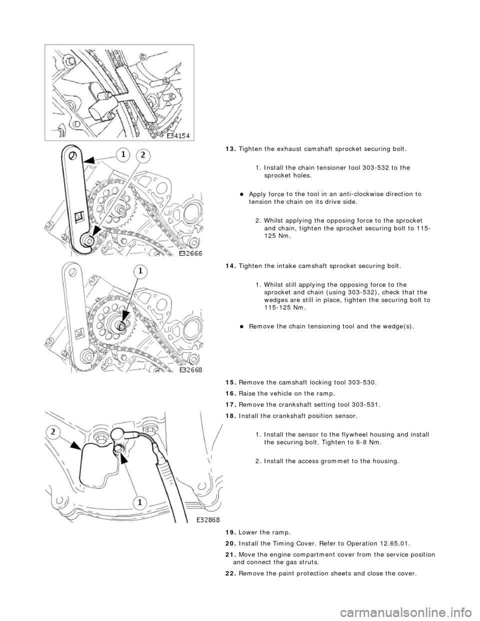
13. Tigh
ten the exhaust camshaft
sprocket securing bolt.
1. Install the chain tensioner tool 303-532 to the sprocket holes.
Appl y force
to the tool in an
anti-clockwise direction to
tension the chain on its drive side.
2. Whilst applying the opposing force to the sprocket and chain, tighten the sprock et securing bolt to 115-
125 Nm.
14 .
Tigh
ten the intake camshaft
sprocket securing bolt.
1. Whilst still applying the opposing force to the
sprocket and chain (using 303-532), check that the
wedges are still in place, ti ghten the securing bolt to
115-125 Nm.
R e
move the chain tensioning
tool and the wedge(s).
15. Remove the camshaft locking tool 303-530.
16. Raise the vehicle on the ramp.
17. Remove the crankshaft setting tool 303-531.
18 . Inst
all the crankshaft position sensor.
1. Install the sensor to the flywheel housing and install
the securing bolt. Tighten to 6-8 Nm.
2. Install the access grommet to the housing.
19. Lower the ramp.
20. Install the Timing Cover. Refer to Operation 12.65.01.
21. Move the engine compartment cover from the service position
and connect the gas struts.
22. Remove the paint protection sheets and close the cover.