vi number JAGUAR X308 1998 2.G Workshop Manual
[x] Cancel search | Manufacturer: JAGUAR, Model Year: 1998, Model line: X308, Model: JAGUAR X308 1998 2.GPages: 2490, PDF Size: 69.81 MB
Page 35 of 2490
General Infor
mation - Gene
ral Service Information
Description an
d Operation
Safety Notice
Appropri
ate service me
thods and proper repair procedures are essential for the safe, reliable operation of all motor vehicles,
as well as the safety of the person do ing the work. This manual provides genera l directions for accomplishing service and
repair work with tested, effect ive, techniques. Following them will help assure reliability.
There are numerous variations in procedures, techniques, tools, and parts for servicing vehicles, as well as in the skill of the
person doing the work. This manual cannot possibly anticipate all such variations and provide advice or cautions as to each.
Accordingly, anyone who depart s from the instructions provided in the manua l must first establish that neither personal
safety nor vehicle integrity is compromised from choices of methods, tools or parts.
Notes, Ca
utions and Warnings
Throughout
this manual, important inform
ation is highlighted by the use of notes, cautions and warnings. NOTES give
additional information on a topic or proc edure, CAUTIONS are given to prevent da mage to the vehicle, and WARNINGS are
given to prevent personal injury.
Worksh
op Manual Organization
This
manual incorporates descript
ive, diagnostic, and repair information to help trained Jaguar technicians complete service
and rectification procedures. The informat ion can be accessed by choosing the appropriate five digit section number. For
example, Section 412-03 covers air conditioning , which is part of the Climate Control System.
The manual is organized into groups covering generic aspects of the vehicle systems; the first digit of the section
number represents a group se lected from the following:
1. General Information.
2. Chassis.
3. Powertrain.
4. Electrical.
5. Body and Paint.
Each of the groups comprises sections re lating to specific areas of the vehicle.
The second and third digits of the section number indicate the vehicle system.
The last two digits of the se ction number define the system covered, more specifically.
Each section comprises one or more of the following sub-sections:
Specification
Page 36 of 2490
Gener
al specifications (including setting-up information, capacities, lubricants, fluids, sealants and adhesives).
To
r
que specifications.
Description and Operation
A g
eneral illustration and part
s list to identify the components which comp rise a particular system or assembly.
A b
rief description of the system operating characteristics or description of the assembly.
A d
escription of each component and its function.
Diagnosis and Testing
D e
scriptions of how to iden
tify system problems.
Inspection and verifi
cation information.
S
y
mptom charts comprising fault conditions, possible sources and actions.
General Procedures
G e
neral maintenance procedures, including adjustment, alig
nment, bleeding and filling, with illustrated steps and
supporting text.
Tigh te
ning torque specifications, shown in the illustrations.
Removal and Installation
Com p
onent removal and installation maintenance proced
ures, with illustrated steps and supporting text.
Tighte
ning torque specifications, shown in the illustrations.
An i
llustrated tool
chart for each proced
ure requiring the use of special tools.
Disassembly and Assembly
Compon ent disassembly and
assembly
maintenance procedures, with illust rated steps and supporting text.
Tighte
ning torque specifications, shown in the illustrations.
An i
llustrated tool
chart for each proced
ure requiring the use of special tools.
Repairs and Replacem
ents
Wh
en s
ervice parts are required, it is essential that only genuine Jaguar/Daimler replacements are used.
Attention is drawn to the following points concerning repa irs and the fitting of replacement parts and accessories:
Safety feat
ures embodied in the vehicle
may be impaired if other than genuine parts are fitted. In certain territories,
legislation prohibits the fitting of pa rts which are not produced to the vehi cle manufacturer's specification.
Torque wrench setting figures given i
n this manual must be strictly adhered to. Locking devices, where specified,
must be fitted. If the efficiency of a locking device is impaired during removal it must be renewed.
O w
ners purchasing accessories
while travelling abroad should ensure that the accessory and its fitted location on the
vehicle conform to mandatory requirements existing in their country of origin.
The vehicle warranty may be invali
dated by the fitting
of other than genuine Ja guar/Daimler parts. All
Jaguar/Daimler replacements have the fu ll backing of the factory warranty.
Jaguar/Daimler dealers are obliged to
supply only genuine service parts.
Thread Locking Devices
P a
tched Fasteners
Two types
of
patched fastener are essentially used on certai
n suspension, steering and other critical components, where
operational movement of the component necessitates positive thread locking. Standard patched fasteners have part
numbers bearing the suffix le tter M. For identification of special patched fa steners, refer to the list of patched fasteners
below, or the relevant component drawings.
Jaguar Specification JFS 02.01.02 patched fasteners incorporate a micro-encapsulated adhesive which is released into the
mating threads during tightening. Following final tightening, the adhesive in this type of patched fastener must be allowed a
period to cure before the component/vehicle is used. On removal, this type of fastener must be discarded and a new
Page 37 of 2490
patc
hed fastener of the same specification fitted. All mating th
reads must be thoroughly cleaned prior to fitting of the new
fastener.
Jaguar Specification JFS 02.01.04 patched fasteners incorporat e a plastic/polyester on the thread. Acting as a wedge
between the mating threads, this compound imposes a prevaili ng torque during tightening. Whilst this type of patched
fastener can be re-used, the imposed torq ue diminishes. It is therefore recommended that following third removal, this type
of patched fastener is discarded and a new fast ener of the same specification is fitted.
Special fasteners bearing the following pa rt numbers are of the micro-encapsulated adhesive type and following removal,
must be discarded and replaced by ne w items of the same specification:
CAC 8223
JZB 10060; JZB 10061; JZB 10078.
JZH 100027.
JZS 100082; JZS100087; JZS 100088; JZS 100089; JZS 100090; JZS 100118; JZS 100157; JZS 100164; JZS 100166.
NCA 1451 AA.
Vehicle Specifications
Purchasers are advised th
at th
e specification details set out in this manual apply to a range of vehicles and not to any
specific one. For the specificatio n of a particular vehicle, purchasers should consult their dealer.
The Manufacturer reserves the right to vary the specifications, with or without notice, and at such times and in such manner
as the Manufacturer thinks fit. Major as well as minor changes may be involved , in accordance with the Manufacturer's
policy of continuous improvement.
Whilst every effort is made to ensure the accuracy of the pa rticulars contained in this manual, neither the Manufacturer nor
the Dealer, by whom the manual is supplied, shall in any circumstances be held liable for any inaccuracy or the
consequences thereof.
Serv
ice Repair Operation Numbering
A
master index of numbered operations has been compiled for
universal application to all vehicles manufactured by Jaguar
Cars Ltd.
Each operation is allocated a number from the master index and cross-refers with an identical number in the Repair
Operation Times schedule. The number consists of six digits arranged in three pairs.
Each maintenance procedure in this manual is described in the sequence necessary to complete the operation in the
minimum time, as specified in the Repair Operation Times schedule for this range of vehicles.
Re
ferences to Left- and Right-Hand
R
eferences to the left- or
right-hand side of the vehicle are made as if viewing from the driver's seat.
Ref
erences to Engine Banks
Wi
th the engine installed in the vehicle, the right-hand cylinder
bank is designated Bank A, and the left-hand cylinder bank
is designated Bank B.
Specia
l Tools
Any special too
ls and equipment required
to perform a maintenance procedure, are shown at the beginning of each
maintenance procedure.
Page 46 of 2490
Meter (measurement)m
Me
tric (screw thread, e.g.
M8)
M
MicrofaradMFDUni t
of electrical capacitance, one millionth of a farad
Mi
ll
imeter
mm
Mi
ll
imeter of mercury
mm
Hg
Mill
isecond
ms
Min
i
mum
mi
n.
Min u
te
minut
e
Model YearMY
ModuleMSelf
contained group of electrical/electronic components which is designed as
a single replaceable unit
Modulating signalMDA sh
ift process signal to the TCM on SC vehicles
Motorized In
-Car
AspiratorMIAD e
vice which constantly samples cabi
n temperature by passing air over a
sensor, and communicates with the A/ CCM to modify A/C system performance
to suit
Mult i Prot
ocol Adaptor
MPAAn i
n
terpreter for the various data
languages present on a vehicle
N
Nati
onal Institute of
Occupational Safety and
Health (US)
NIO S
H
Ne
wto
n
NSI unit of force. 1
N = 0.224
8 pounds force
Ne
wto
n meter
NmSI unit of torque. Must not be
co
nfused with nm (nanometer)
Ni
tr
ous Oxide
NO
xCompounds of nit rogen and oxygen fo rmed at high temperatures. Major
sourc
e of exhaust-gas air pollution
No
n
-Volatile Random
Access Memory
NVR A
M
R
A
M which retains memory even
if power supply is interrupted
Normal
ly aspirated
F
u
eling system using intake air at atmo
spheric pressure; not supercharged or
turbocharged
N ormal
ly Closed
NC
N
o
rmally Open
NO
No
r
th American
Specification
NASVehicles f or sal
e in the USA and Canadian markets
Nu
mbe
r
No
.
O
Oc
cupational Safety and
Health Administration
(US)
OS H
A
O
n
-Board Diagnostic
OB
DA system that moni
tors some or all co
mputer input and output control signals.
Signal(s) outside the pre-de termined limits imply a fault in the system or a
related system
O n
-Board Refueling
Vapor Recovery
OR V
R
O
riginal
Equipment
Manufacturer
OE M
Outp
ut
O/
PAn electrical o u
tput signal from a controlling device
Ou
ts
ide diameter
o.
d
ia
O
xides of
nitrogen
NO
x
Oxygen senso
r
O2
SA s
ensor which detects oxygen content in the exhaust gases
P
Parameter Identifi
erPIDAn in
dex number referring to a parame
ter within a module without knowledge
of its storage location
Park N e
utral Position
PN
P
Park N e
utral Position
Switch
PN PSIndic
ates the selected non-drive modes of the (automatic) transmission
Part numberpart no.
Portable Diag
nostic Un
it
PD
UCompre hen
sive electrical diagnosis system specific to Jaguar vehicles
Posi
ti
on
po
s'n
Power As si
sted Steering
PASHydraul
i
c pump-assisted steering system
Power Steer
i
ng Pressure
PSP
Programmable Elect
r
onic
Control Units System
PECU SProcess whereb y
a common ECM is progra
mmed on the production line to suit
the market requirements of a particular vehicle
Programmable Read-O
nly
PROMRO
M with some provision for setting
the stored data after manufacture
Page 47 of 2490
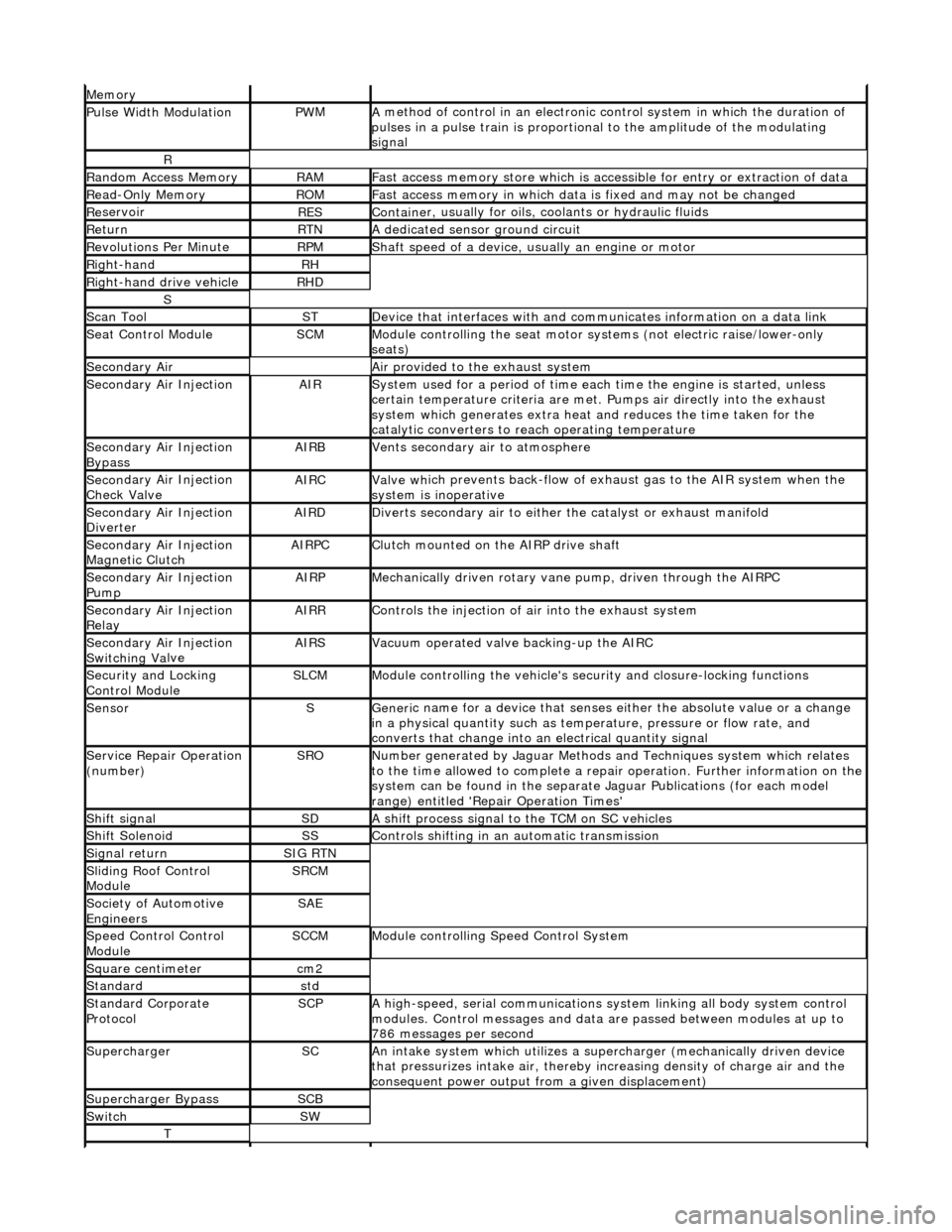
Mem
ory
Pulse Width ModulationPW
M
A
method of control in an electronic co
ntrol system in which the duration of
pulses in a pulse train is proportional to the amplitude of the modulating
signal
R
Ran
dom Access Memory
RAMF
ast access memory store which is accessible for entry or extraction of data
Re
ad-Only Memory
RO
M
F
ast access memory in which data
is fixed and may not be changed
Re
servoir
RESContaine
r, usually for oils,
coolants or hydraulic fluids
Re
turn
RTNA
dedicated sensor ground circuit
R
evolutions Per Minute
RP
M
Shaft speed o
f a device, us
ually an engine or motor
R
ight-hand
RH
Right-hand drive veh
icle
RHD
S
Scan T
ool
STDe
vice that interfaces with and comm
unicates information on a data link
Se
at Control Module
SCMModule
controlling the seat motor systems (not electric raise/lower-only
seats)
Secon
dary Air
Air pro
vided to the exhaust system
Secon
dary Air Injection
AIRSy
stem used for a period of time each
time the engine is started, unless
certain temperature criter ia are met. Pumps air directly into the exhaust
system which generates extra heat and reduces the time taken for the
catalytic converters to reach operating temperature
Secon
dary Air Injection
Bypass
AIRBVents secon
dary air to atmosphere
Secon
dary Air Injection
Check Valve
AIRCValve wh
ich prevents back-flow of exhaust gas to the AIR system when the
system is inoperative
Secon
dary Air Injection
Diverter
AIRDD
iverts secondary air to either
the catalyst or exhaust manifold
Secon
dary Air Injection
Magnetic Clutch
AIRP
C
Clu
tch mounted on the AIRP drive shaft
Secon
dary Air Injection
Pump
AIRPMe
chanically driven rotary vane
pump, driven through the AIRPC
Secon
dary Air Injection
Relay
AIRRCont
rols the injection of air into the exhaust system
Secon
dary Air Injection
Switchin
g Va
lve
AIRSV
acuum operated valve backing-up the AIRC
Secu
rity and Locking
Control Module
SLCMModul
e controlling the vehicle's security and closure-locking functions
SensorSGeneri
c name for a device
that senses either the absolute value or a change
in a physical quantity su ch as temperature, pressure or flow rate, and
converts that change into an electrical quantity signal
Servic
e Repair Operation
(number)
SRONu
mber generated by Jaguar Methods
and Techniques system which relates
to the time allowed to complete a repair operation. Further information on the
system can be found in the separate Jaguar Publications (for each model
range) entitled 'Repair Operation Times'
Shif
t signal
SDA
shift process signal to the TCM on SC vehicles
Shif
t Solenoid
SSControls shi
fting in an automatic transmission
Si
gnal return
SIG RTN
Slidin
g Roof Control
Module
SRCM
Society of Automotive
Engineers
SAE
Speed
Control Control
Module
SCCMModule con
trolling Speed Control System
Square c
entimeter
cm
2
Stan
dard
std
Stan
dard Corporate
Protocol
SCPA
high-speed, serial communications system linking all body system control
modules. Control messages and data ar e passed between modules at up to
786 messages per second
SuperchargerSCAn in
take system which utilizes a supercharger (mechanically driven device
that pressurizes intake air, thereby in creasing density of charge air and the
consequent power output from a given displacement)
Supercharger
Bypass
SCB
SwitchSW
T
Page 48 of 2490
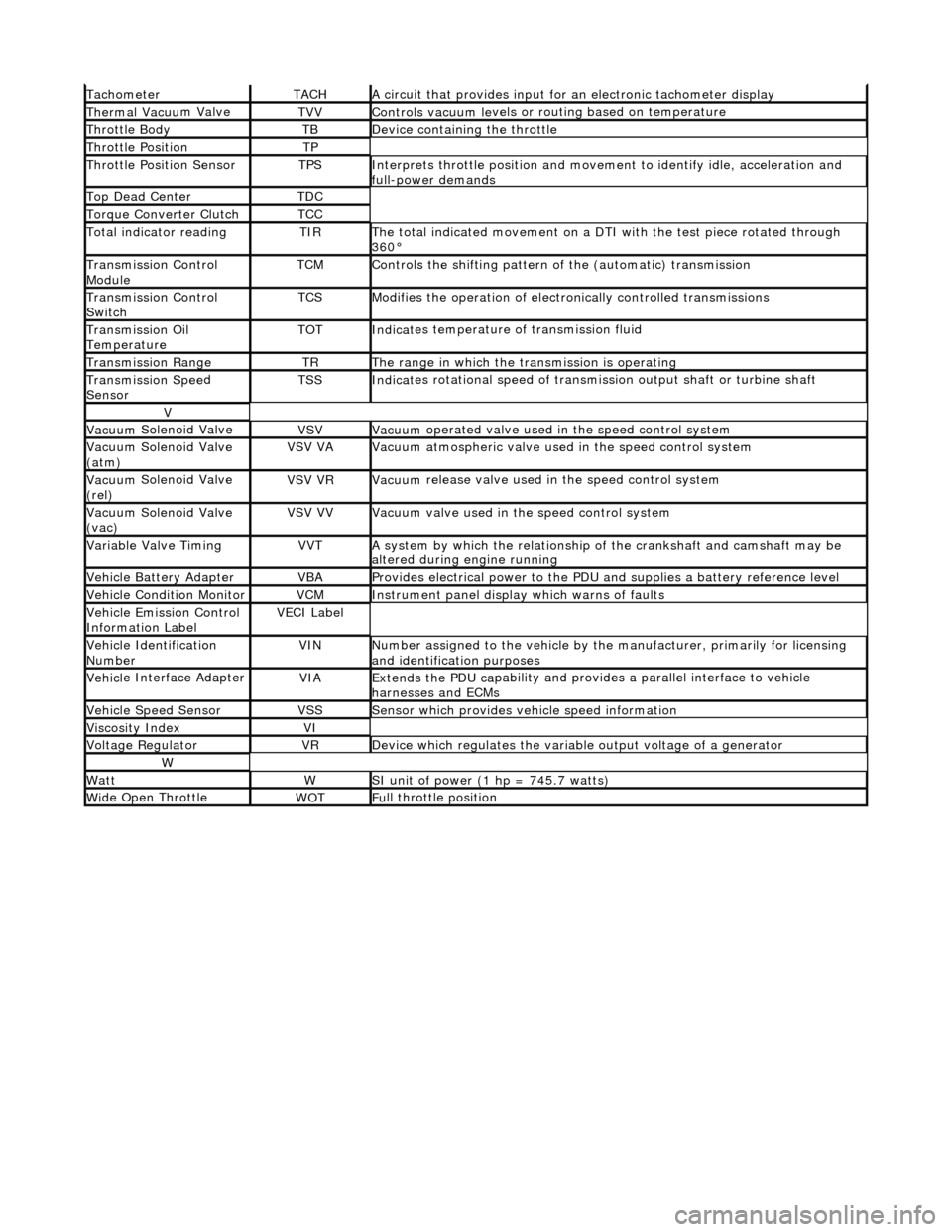
Tacho
meter
TACHA
ci
rcuit that provides input for
an electronic tachometer display
Thermal Vacuu
m Valve
TVVControls vacuum l
e
vels or
routing based on temperature
Throttle
Body
TBDe
vi
ce containing the throttle
Throttl
e
Position
TP
Throttl
e
Position Sensor
TPSInterprets throttl
e
position and movement to iden tify idle, acceleration and
full-power demands
Top Dead CenterTDC
Torque Converter C
lutch
TCC
To
tal
indicator reading
TIRThe t
o
tal indicated movement on a DTI with the test piece rotated through
360°
Transm
ission Control
Module
TCMControls
the shifting pattern
of the (automatic) transmission
Transm
ission Control
Switch
TCSModifi es
the operation of electronically controlled transmissions
Transmission Oil
TemperatureTOTIndi
cat
es temperature of transmission fluid
Transmission RangeTRThe ran
g
e in which the transmission is operating
Transmission Spe
e
d
Sensor
TSSIndi cat
es rotational speed of transmission output shaft or turbine shaft
V
Vacuu
m
Solenoid Valve
VSVVacuu
m
operated valve used in the speed control system
Vacuu
m
Solenoid Valve
(atm)
VSV VAVacuu m
atmospheric valve used in the speed control system
Vacuu
m
Solenoid Valve
(rel)
VSV VRVacuu m
release valve used in the speed control system
Vacuu
m
Solenoid Valve
(vac)
VSV VVVacuu m
valve used in the speed control system
Variable Valve TimingVVTA
s
ystem by which the relationship of the crankshaft and camshaft may be
altered during engine running
Vehi cl
e Battery Adapter
VBAProvide
s
electrical power to the PDU
and supplies a battery reference level
Vehicl
e Condition Monitor
VCMInst
rum
ent panel display which warns of faults
Ve
hic
le Emission Control
Information Label
VECI Label
Vehi cl
e Identification
Number
VINN u
mber assigned to the vehicle by the manufacturer, primarily for licensing
and identification purposes
Vehi cl
e Interface Adapter
VIAExtends the
PDU ca
pability and provid
es a parallel interface to vehicle
harnesses and ECMs
Vehicle Spe e
d Sensor
VSSSens
or which provides ve
hicle speed information
Viscosity In
dexVI
Voltage RegulatorVRDe
vice which regulates the variable output voltage of a generator
W
Wat
tWSI unit of power (1 hp = 7
45.7 watts)
W
i
de Open Throttle
WO
TFu
ll throttle position
Page 49 of 2490
Identification
Codes -
Identification Codes
Descr
iption and Operation
En
gine Number
The en
gine number (10 digits) is stamped on a raised pad on th
e front of the engine block near the thermostat housing. The
piston grade reference (8 digits) is also shown.
Automatic Transmission
Number
The
serial number of the transmission unit is displayed on
a metal or bar code label attached to the LH side of the
transmission casing.
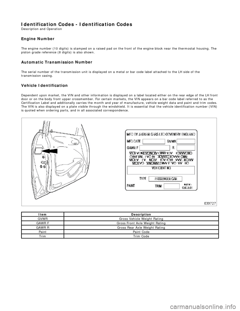
Veh
icle Identification
Dependent
upon market, the VIN and other info
rmation is displayed on a label located ei ther on the rear edge of the LH front
door or on the body front upper crossmember. For certain mark ets, the VIN appears on a bar code label referred to as the
Certification Label and additionally carries the month and year of manufacture, vehicle weight data and paint and trim codes.
The VIN is also displayed on a plate visible through the windshie ld. It is essential that the vehicle identification number (VIN)
is quoted when ordering parts, and in all associated correspondence.
ItemDe
scription
GVW
R
G
ross Vehicle Weight Rating
GAW
R F
Gros
s Front Axle Weight Rating
GAW
R R
Gros
s Rear Axle Weight Rating
Pai
nt
Pai
nt Code
TrimTrim
Code
Page 54 of 2490
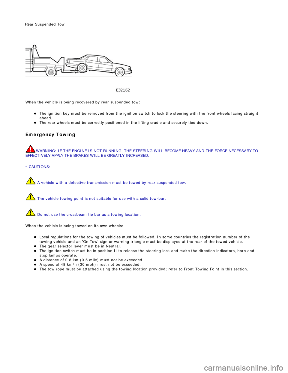
Wh en t
he vehicle is being reco
vered by rear suspended tow:
The ignition key must be remo ved from the ig
nition switch to lock the stee
ring with the front wheels facing straight
ahead.
The re ar
wheels must be
correctly positioned in the lifting cradle and securely tied down.
Em
ergency Towing
WARNING: IF THE
ENGINE IS NOT
RUNNING, THE STEERING WILL BECOME HEAVY AND THE FORCE NECESSARY TO
EFFECTIVELY APPLY THE BRAKES WILL BE GREATLY INCREASED.
• CAUTIONS:
A vehicle with a defective transmission must be towed by rear suspended tow.
The vehicle towing point is not suit able for use with a solid tow-bar.
Do not use the crossbeam tie bar as a towing location.
When the vehicle is being towed on its own wheels:
Loc a
l regulations for the towing of ve
hicles must be followed. In some co untries the registration number of the
towing vehicle and an 'On Tow' sign or warning triangle must be displayed at the rear of the towed vehicle.
The gear s
elector lever
must be in Neutral.
The
ignition switch must be in positi
on II to release the steering lock and make the direction indicators, horn and
stop lamps operate.
A di
stance of 0.8 km (0.5 mi
le) must not be exceeded.
A spe
ed of 48 km/h (30 mph) must not be exceeded.
The tow rope must be attached using th
e towi
ng location provided; refer to Front Towing Point in this section.
Rear Su
spended
Tow
Page 55 of 2490
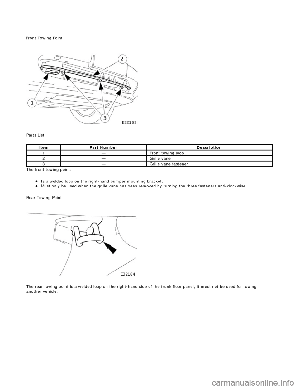
P
arts List
The front towing point:
Is a welded loop on the ri
ght-ha
nd bumper mounting bracket.
Mus
t only be used when the grille
vane has been removed by turning the three fasteners anti-clockwise.
Rear Towing Point
The rear towing point is a welded loop on the right-hand side of the trunk floor panel; it must not be used for towing
another vehicle.
It
em
Par
t Number
De
scription
1—Fr
ont towing loop
2—Gr
ille vane
3—Gr
ille vane fastener
F
ront Towing Point
Page 68 of 2490
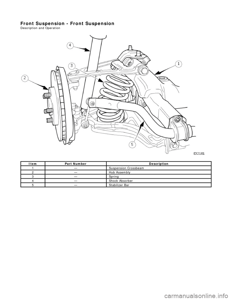
Front Suspension - Front Suspension
Description and Operation
Ite
m
Par
t
Number
De
scr
iption
1—Suspensi
on C
rossbeam
2—Hub Assembly
3—Sprin
g
4—Shock Absorber
5—St
abil
izer Bar