fuel JAGUAR XF 2009 1.G AJ133 5.0L Engine Manual
[x] Cancel search | Manufacturer: JAGUAR, Model Year: 2009, Model line: XF, Model: JAGUAR XF 2009 1.GPages: 36, PDF Size: 0.38 MB
Page 3 of 36

Technical Training
NP10-V8JLR: AJ133 5.0-Liter DFI V8 Engine 04/14/2009
3-1
Engine Management System
Table of Contents
Overview . . . . . . . . . . . . . . . . . . . . . . . . . . . . . . . . . 2
Engine Control Module . . . . . . . . . . . . . . . . . . . . . . 8
Relays . . . . . . . . . . . . . . . . . . . . . . . . . . . . . . . . . . . 10
Crankshaft Position Sensor . . . . . . . . . . . . . . . . . . 11
Camshaft Position Sensor . . . . . . . . . . . . . . . . . . . 13
Engine Coolant Temperature Sensor . . . . . . . . . . 14
Knock Sensors . . . . . . . . . . . . . . . . . . . . . . . . . . . . 15
Manifold Absolute Pressure Sensor . . . . . . . . . . . 16
Mass Air Flow Sensor . . . . . . . . . . . . . . . . . . . . . . 17
Temp. / Manifold Absolute Pressure Sensor . . . . 18
Throttle Position Sensor . . . . . . . . . . . . . . . . . . . . 19
Accelerator Pedal Position Sensor . . . . . . . . . . . . 21
Heated Oxygen Sensors . . . . . . . . . . . . . . . . . . . . 22
Ambient Air Temperature Sensor. . . . . . . . . . . . . 26
Ignition Coils . . . . . . . . . . . . . . . . . . . . . . . . . . . . . 27
Fuel Tank Canister Purge Valve . . . . . . . . . . . . . . 28
Viscous Fan Control (Land Rover only) . . . . . . . 29
Controller Area Network. . . . . . . . . . . . . . . . . . . . 30
On-Board Diagnostic Monitoring . . . . . . . . . . . . . 31
Crankcase Ventilation System . . . . . . . . . . . . . . . 32
Page 4 of 36

3-2
04/14/2009 NP10-V8JLR: AJ133 5.0-Liter DFI V8 Engine
Technical Training
Overview
Engine Management System
OVERVIEW
The 5.0-Liter V8 normally aspirated (NA) and super-
charged (SC) engines are managed by the engine control
module (ECM), which controls the following:
• Engine fuel metering
• Ignition timing
• Camshaft timing
• Camshaft Profile Switching (CPS)
• Closed loop fuel metering
• Knock control
• Idle speed control
• Emission control
• On-Board Diagnostics (OBD)
• Interface with the immobilization system
• Speed control
The ECM controls the engine fuel metering by provid-
ing sequential fuel injection to all cylinders. Ignition is
controlled by a direct ignition system, provided by eight
coil-on-plug (COP) units. The ECM is able to detect and
correct for ignition knock on each cylinder and adjust the
ignition timing for each cylinder to achieve optimum
performance.
The ECM uses a torque-based strategy to generate the
torque required by driver demand and the other vehicle
control modules, using input from various sensors to cal-
culate the required torque. The ECM also interfaces with
other vehicle electronic control modules to obtain addi-
tional information (road speed from the ABS control
module, for example). The ECM processes these signals
and determines how much torque to generate, using vari-
ous actuators to supply air, fuel, and spark to the engine
(electronic throttle, injectors, coils, etc.).
Page 5 of 36
Technical Training
NP10-V8JLR: AJ133 5.0-Liter DFI V8 Engine 04/14/2009
3-3
Engine Management System
Overview
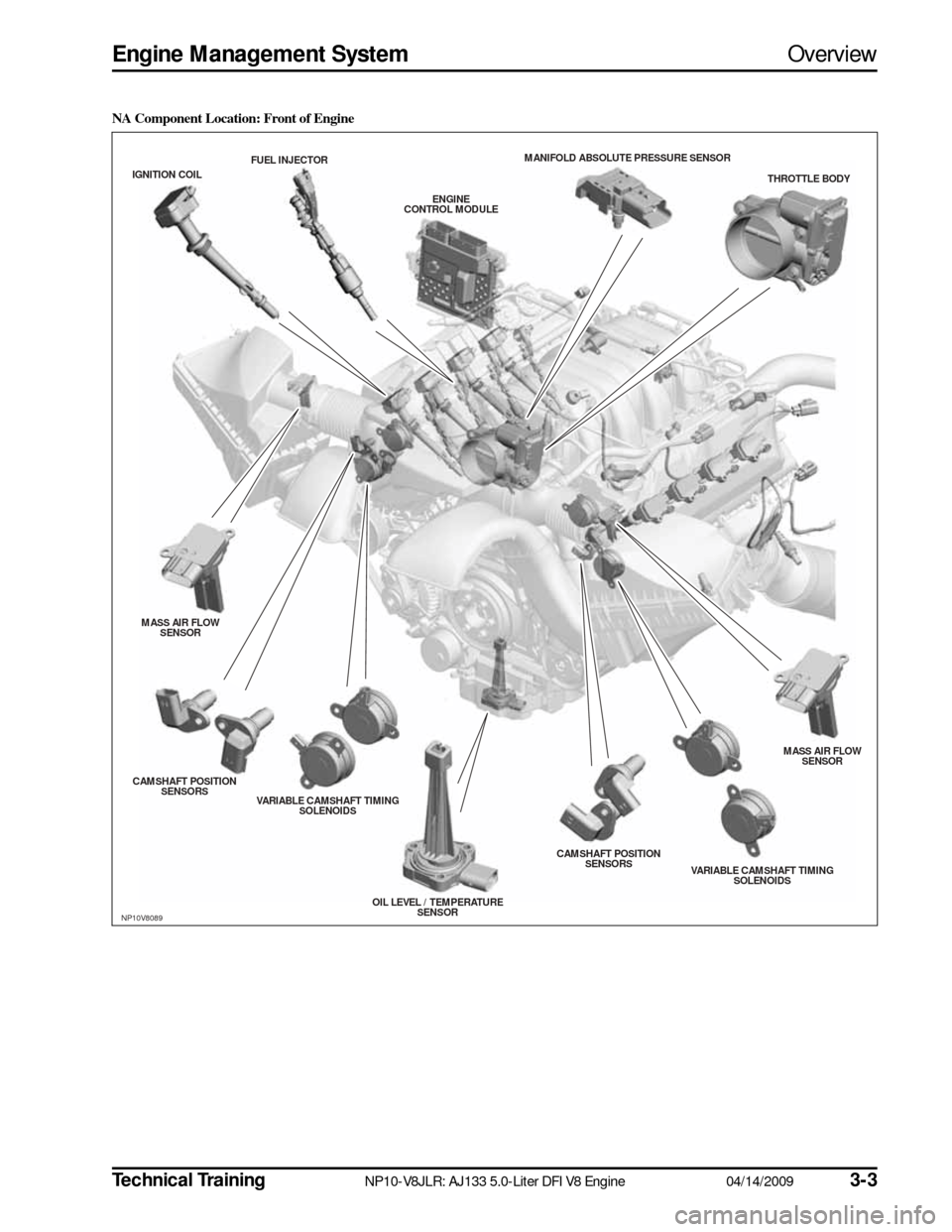
NA Component Location: Front of Engine
NP10V8089
THROTTLE BODY
MANIFOLD ABS
OLUTE PRESSURE S ENSOR
ENGINE
CONTROL MODULE
FUEL INJECTOR
IGNITION COIL
MASS AIR FLOW SENS OR
CAMS HAFT POS ITION
S ENS ORS
VARIABLE CAMS HAFT TIMING
S OLENOIDS
OIL LEVEL / TEMPERATURESENS OR CAMS
HAFT POS ITION
S ENS ORS
VARIABLE CAMSHAFT TIMING
S OLENOIDS MASS AIR FLOW
SENS OR
Page 6 of 36
3-4
04/14/2009 NP10-V8JLR: AJ133 5.0-Liter DFI V8 Engine
Technical Training
Overview
Engine Management System
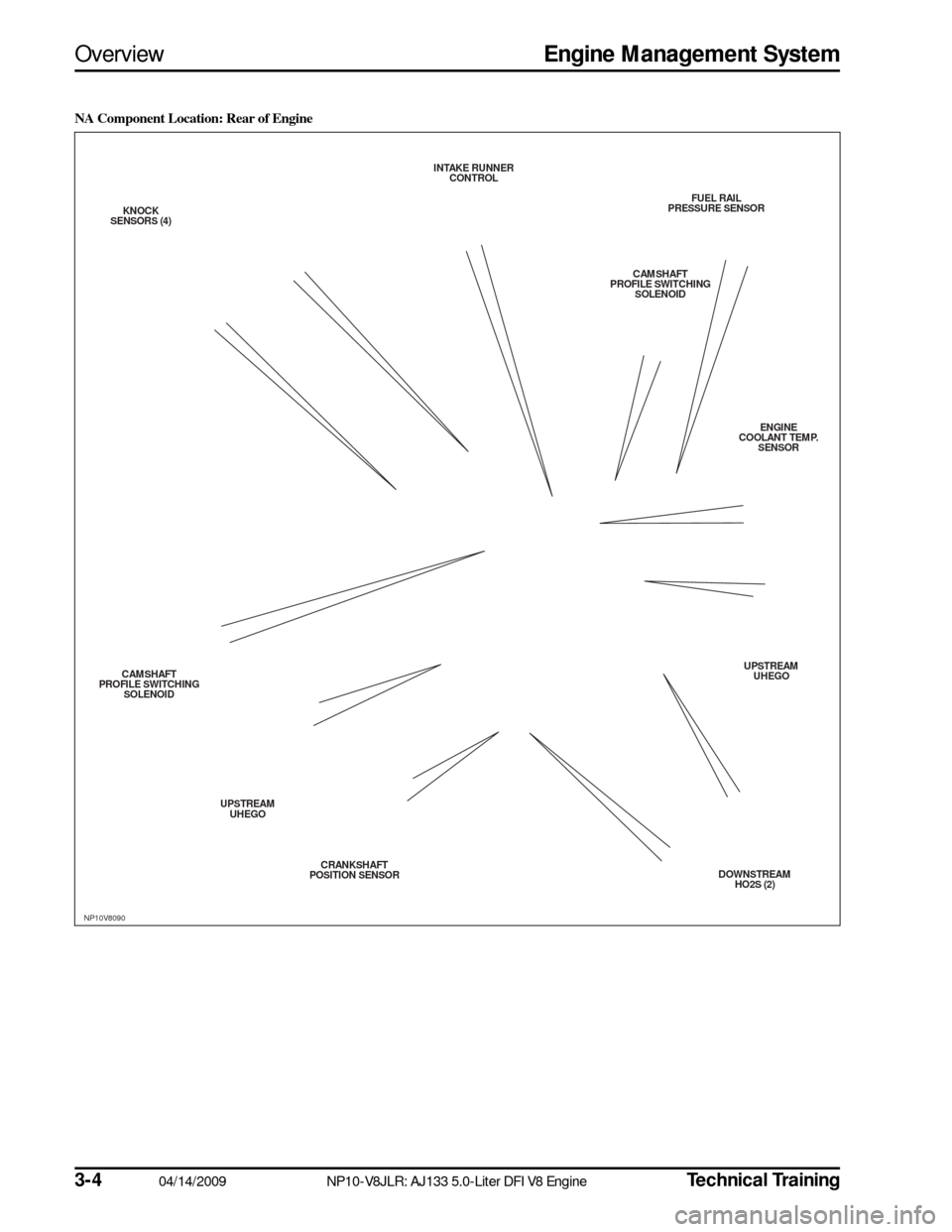
NA Component Location: Rear of Engine
NP10V8090
FUEL RAIL
PRESSURE S ENSOR
CAMS HAFT
PROFILE S WITCHING
S OLENOID
ENGINE
COOLANT TEMP. SENS OR
UPS TREAM
UHEGO
DOWNS TREAM
HO2S (2)
CRANKS
HAFT
POS ITION S ENSOR
UPS
TREAM
UHEGO
CAMS
HAFT
PROFILE S WITCHING
S OLENOID
KNOCK
S ENS ORS (4) INTAKE RUNNER
CONTROL
Page 7 of 36
Technical Training
NP10-V8JLR: AJ133 5.0-Liter DFI V8 Engine 04/14/2009
3-5
Engine Management System
Overview
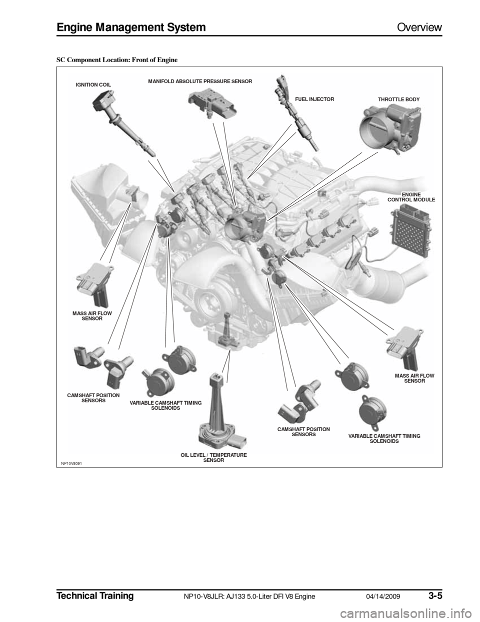
SC Component Location: Front of Engine
NP10V8091
THROTTLE BODY
MANIFOLD ABS
OLUTE PRESSURE S ENSOR
ENGINE
ENGINECONTROL MODULECONTROL MODULEENGINE
CONTROL MODULE
FUEL INJECTOR
IGNITION COIL
MASS AIR FLOW SENS OR
CAMS HAFT POS ITION
S ENS ORS
VARIABLE CAMS HAFT TIMING
S OLENOIDS
OIL LEVEL / TEMPERATURESENS OR CAMS
HAFT POS ITION
S ENS ORS
VARIABLE CAMSHAFT TIMING
S OLENOIDS MASS AIR FLOW
SENS OR
Page 8 of 36
3-6
04/14/2009 NP10-V8JLR: AJ133 5.0-Liter DFI V8 Engine
Technical Training
Overview
Engine Management System
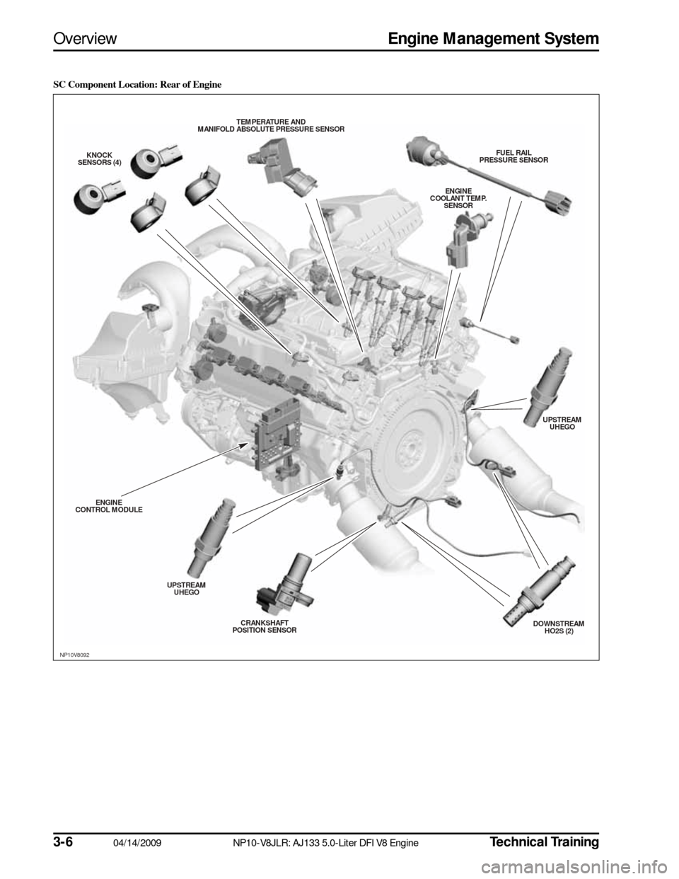
SC Component Location: Rear of Engine
NP10V8092
FUEL RAIL
PRESSURE S ENSOR
ENGINE
COOLANT TEMP. SENS OR
UPSTREAM
UHEGO
DOWNS TREAM
HO2S (2)
CRANKS
HAFT
POS ITION S ENSOR
UPS
TREAM
UHEGO
ENGINE
CONTROL MODULE KNOCK
S ENS ORS (4) TEMPERATURE AND
MANIFOLD ABS OLUTE PRESSURE S ENSOR
Page 10 of 36

3-8
04/14/2009 NP10-V8JLR: AJ133 5.0-Liter DFI V8 Engine
Technical Training
Engine Control Module
Engine Management System
ENGINE CONTROL MODULE
The ECM is supplied with battery voltage from a 5A fuse and an ignition supply from the ECM relays through\
a 15A
fuse, both located in the CJB. A regulator located within the ECM supplies a 5V current to internal compone\
nts such
as the microprocessor unit. Other components or functions requiring full\
battery voltage are controlled by external
relays or internal switching modules.
The microprocessor within the ECM receives signals from different components and control modules and uses a pro-
gram within the ECM software to interpret the signal information and issue signals which relate t\
o how the engine
components and functions should be controlled. The ECM communicates with other control modules via bidirectional
Controller Area Network (CAN) communication interfaces.
The ECM uses the following inputs and outputs:
Inputs
• Camshaft position (CMP) sensor
• Crankshaft position (CKP) sensor
• Fuel rail high-pressure sensor
• Mass air flow (MAF) sensors (2)
• Knock sensors (4)
• Engine coolant temperature (ECT) sensor
• Manifold absolute pressure (MAP) sensor
• Electronic throttle position sensor
• Accelerator pedal position (APP) sensor
• Cooling fan speed
• Upstream Universal Heated Exhaust Gas Oxygen (UHEGO) sensors (2)
• Brake switch
• Speed control cancel/suspend switch
• Intake air temperature (IAT) sensor (integrated into the MAF) (2)
• Ambient air temperature (AAT) sensor
• Engine oil level and temperature sensor
• Temperature and manifold absolute pressure (TMAP) sensor (SC only)
Outputs
• Throttle Actuator
• Coil-on-plug (COP) ignition coils (8)
• Upstream Universal Heated Exhaust Gas Oxygen (UHEGO) sensors (2)
• Downstream Heated Oxygen Sensors (HO2S) (2)
• Direct injection fuel injectors (8)
• Variable camshaft timing (VCT) solenoids (4)
• Camshaft profile switching (CPS) solenoids (2)
• Intake manifold tuning solenoid
• Carbon canister purge valve
• Fuel pump relay
• Starter relay
• A/C condenser fan relay
• ECM main relay viscous fan control
• Generator control
• Air flap solenoid (SC only)
• Pump control diagnostics
• Diagnostic Monitoring of Tank Leakage (DMTL)
Page 12 of 36

3-10
04/14/2009 NP10-V8JLR: AJ133 5.0-Liter DFI V8 Engine
Technical Training
Relays
Engine Management System
RELAYS
Main Relay
The main Engine Management System (EMS) relay is
not a main power input; it is used to initiate the power-up
and power-down routines within the ECM.
This input comes from the engine junction box (EJB).
When the ignition is turned on 12V is applied to the igni-
tion sense input. The ECM then starts its power-up rou-
tines and turns on the ECM main relay, the main power
to the ECM and its associated system components.
When the ignition is turned OFF, the ECM will maintain
its powered-up state for several seconds (or up to 20
minutes in extreme cases when cooling fans are
required) while it initiates its power-down routine and,
on completion, will turn off the ECM main relay.
The main relay is located in the EJB. The operation of
the main relay is controlled by the ECM, which provides
a ground path for the main relay coil, energizing the
relay and closing the relay contacts.
The main relay supplies battery voltage to the following
engine sensors and actuators:
• Throttle position (TP) sensor (through ECM)
• Fuel injectors
• Ignition coils
• Coil capacitor
• CPS solenoids
• All heated oxygen sensors
• Evaporative emission (EVAP) canister purge valve
• Diagnostic Monitoring of Tank Leakage (DMTL)
Failure Modes
• Relay drive open circuit
• Short circuit to battery voltage or ground
• Component failure
Failure Symptoms
• Engine will not start
Starter Relay
The starter motor relay is located in the EJB. Operation
of the starter motor relay is controlled by the ECM,
which provides a ground path for the relay coil, energiz-
ing the relay and closing the relay contacts. When the
relay contacts are closed, battery voltage is supplied,
through the starter motor relay, to the starter module
solenoid coil.
The starter solenoid is energized and connects the starter
motor with a direct battery feed to operate the starter
motor.
Once the engine has started, the ECM removes the
starter motor relay ground, opening the relay contacts
and terminating the battery feed to the starter solenoid,
which in turn stops the operation of the starter motor.
NOTE:
Diagnose using Jaguar Land Rover approved
diagnostic equipment.
Page 19 of 36
Technical Training
NP10-V8JLR: AJ133 5.0-Liter DFI V8 Engine 04/14/2009
3-17
Engine Management System
Mass Air Flow Sensor
MASS AIR FLOW SENSOR
Mass air flow is determined by the cooling effect of
intake air passing over a ‘hot film’ element contained
within the device. The higher the air flow the greater the
cooling effect and the lower the electrical resistance of
the ‘hot film’ element. The ECM then uses this analog
signal from the mass air flow (MAF) sensor to calculate
the air mass flowing into the engine.
The measured air mass flow is used in determining the
fuel quantity to be injected in order to maintain the sto-
ichiometric air/fuel mixture required for correct opera-
tion of the engine and exhaust catalysts. Should the
device fail, there is a software backup strategy that will
be activated once a fault has been logged.
The intake air temperature (IAT) sensor is integrated into
the MAF sensor. The IAT sensor is an NTC thermistor,
meaning that the sensor resistance decreases as the sen-
sor temperature increases.
The sensor forms part of a voltage divider chain with an
additional resistor in the ECM. The voltage from this device
changes as the sensor resistance changes, thus relating the
air temperature to the voltage measured by the ECM.
Because the engine requires a twin air intake induction
system, there are two MAF sensors per vehicle.
Safety Precautions CAUTIONS:
• Component should not be dropped or han-dled roughly.
• Ensure that no contamination enters the device.
• Some terminals in MAF and connector are gold-plated for corrosion resistance – DO
NOT probe.
Failure Modes
• Sensor open circuit
• Short circuit to battery voltage or ground
• Contaminated/damaged sensor element
• Air leak after MAF sensor
• Intake air restricted
• Resistance in the harness, causing signal offset
• Damaged sensor element
Failure Symptoms
• During driving the engine rpm might dip (before recovering)
• Difficulty in starting or start/stall
• Poor throttle response/engine performance
• Emissions incorrect
• Lambda control and idle speed control halted
• MAF signal offset
NP10V8102
SpecificationFunction
Supply Voltage 8 – 14V
(rated supply voltage: 14V)
Pin A Output (Vg)
Pin B Ground for Output (Vg)
Pin C Power Source
Pin D IAT Sensor Ground
Pin E IAT Sensor Output
Page 24 of 36
3-2204/14/2009NP10-V8JLR: AJ133 5.0-Liter DFI V8 EngineTechnical Training
Heated Oxygen SensorsEngine Management System
HEATED OXYGEN SENSORS
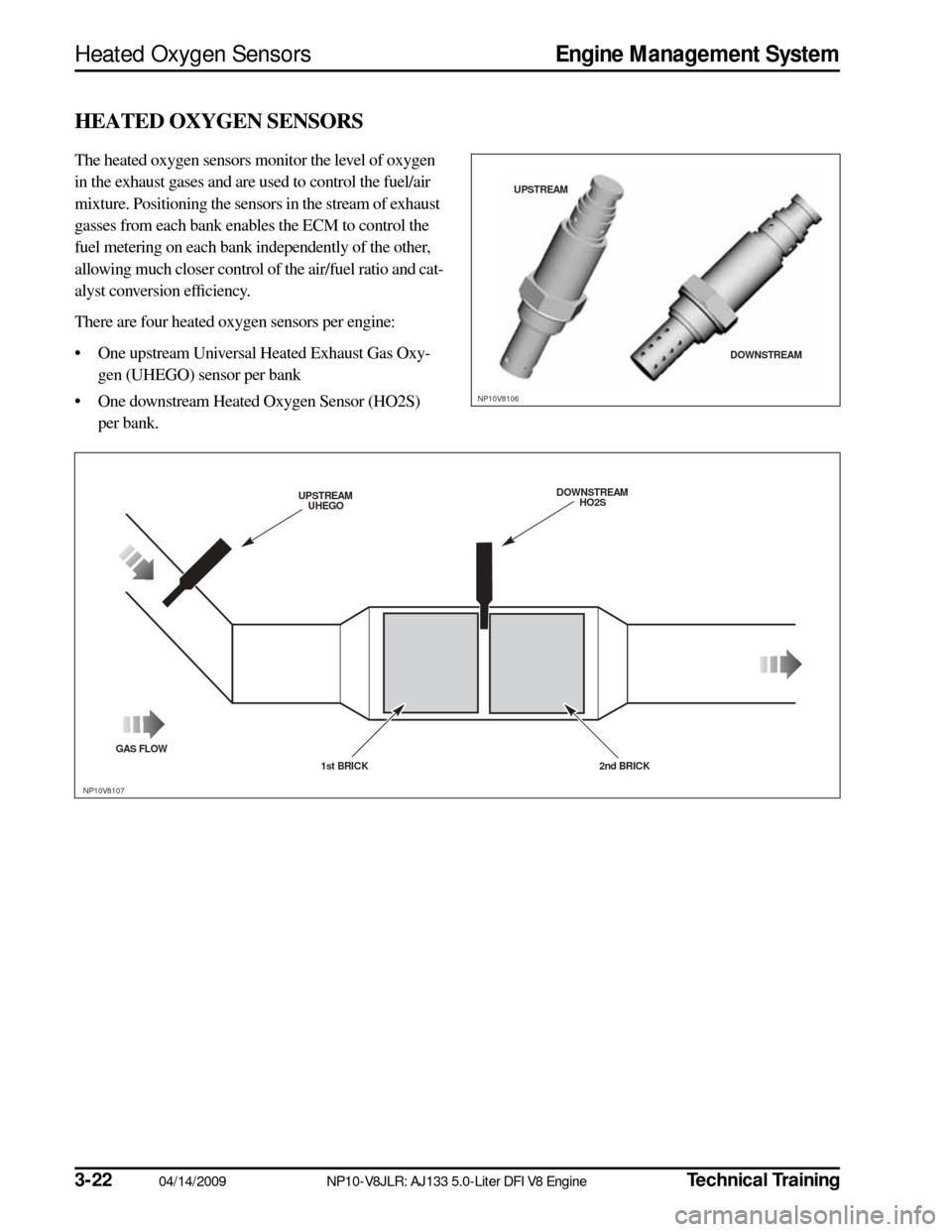
The heated oxygen sensors monitor the level of oxygen
in the exhaust gases and are used to control the fuel/air
mixture. Positioning the sensors in the stream of exhaust
gasses from each bank enables the ECM to control the
fuel metering on each bank independently of the other,
allowing much closer control of the air/fuel ratio and cat-
alyst conversion efficiency.
There are four heated oxygen sensors per engine:
• One upstream Universal Heated Exhaust Gas Oxy-
gen (UHEGO) sensor per bank
• One downstream Heated Oxygen Sensor (HO2S) per bank.
NP10V8106
UPS TREAM
DOWNSTREAM
GAS FLOW
UPSTREAM
UHEGO
1st BRICK 2nd BRICK DOWNS
TREAM
HO2S
NP10V8107