instrument cluster JAGUAR XF 2009 1.G AJ133 5.0L Engine Manual
[x] Cancel search | Manufacturer: JAGUAR, Model Year: 2009, Model line: XF, Model: JAGUAR XF 2009 1.GPages: 36, PDF Size: 0.38 MB
Page 11 of 36

Technical Training
NP10-V8JLR: AJ133 5.0-Liter DFI V8 Engine 04/14/2009
3-9
Engine Management System
Engine Control Module
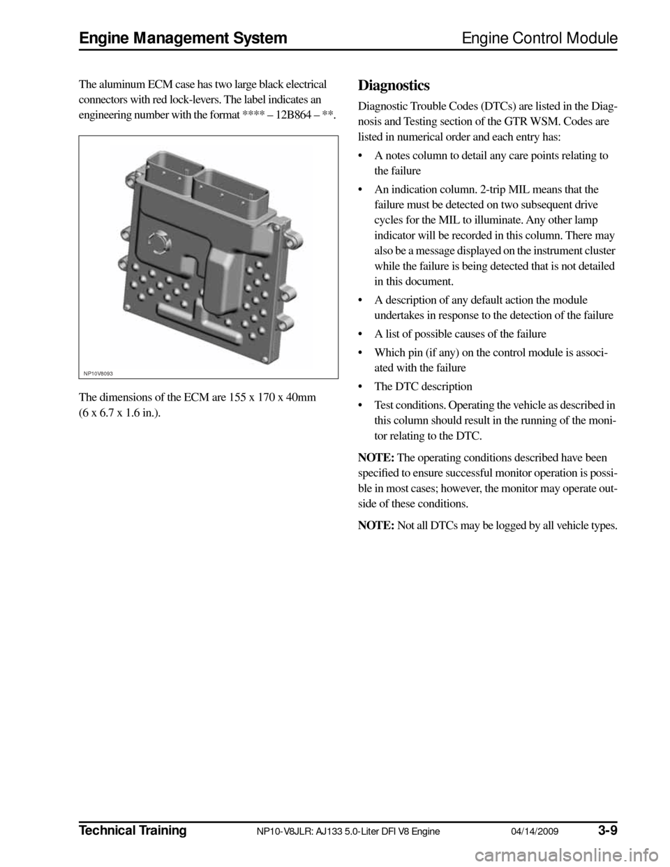
The aluminum ECM case has two large black electrical
connectors with red lock-levers. The label indicates an
engineering number with the format **** – 12B864 – **.
The dimensions of the ECM are 155 x 170 x 40mm
(6 x 6.7 x 1.6 in.). Diagnostics
Diagnostic Trouble Codes (DTCs) are listed in the Diag-
nosis and Testing section of the GTR WSM. Codes are
listed in numerical order and each entry has:
• A notes column to detail any care points relating to the failure
• An indication column. 2-trip MIL means that the failure must be detected on two subsequent drive
cycles for the MIL to illuminate. Any other lamp
indicator will be recorded in this column. There may
also be a message displayed on the instrument cluster
while the failure is being detected that is not detailed
in this document.
• A description of any default action the module undertakes in response to the detection of the failure
• A list of possible causes of the failure
• Which pin (if any) on the control module is associ- ated with the failure
• The DTC description
• Test conditions. Operating the vehicle as described in this column should result in the running of the moni-
tor relating to the DTC.
NOTE:
The operating conditions described have been
specified to ensure successful monitor operation is possi-
ble in most cases; however, the monitor may operate out-
side of these conditions.
NOTE:
Not all DTCs may be logged by all vehicle types.
NP10V8093
Page 32 of 36

3-3004/14/2009NP10-V8JLR: AJ133 5.0-Liter DFI V8 EngineTechnical Training
Controller Area Network Engine Management System
CONTROLLER AREA NETWORK
The Controller Area Network (CAN) is a high-speed
serial interface for sharing dynamic signals between elec-
tronic control modules. CAN communications are ‘self-
checked’ for errors, and if an error is detected the message
is ignored by the receiving electronic control module.
Due to the high rate of information exchange, the system
has a high degree of latency. This allows for a high num-
ber of errors to be present without reducing the data
transfer rate. In practice, this is a very reliable system.
Each CAN message is transmitted by one electronic con-
trol module and received by all other electronic control
modules on the CAN bus. Each message contains a fixed
structure of signals. The data exchanged is used so that
each electronic control module does not need to have a
hardwired sensor for each input. The CAN message iden-
tifiers are arranged by a network tool, which can guarantee
that all messages meet their specified timing needs.
Signal Overview
The CAN communication system is a differential bus
using a twisted pair that is normally very reliable. If either
or both of the wires of the twisted pair CAN bus is open-
or short-circuited, a CAN time-out fault will occur.
Below is a list of additional electronic control modules that
the ECM will communicate with on the CAN network:
• Instrument cluster
• Steering angle sensor
•TCM
• Active rear locking differential, if equipped
• Adaptive cruise control
• Electronic parking brake
Failure Modes
• CAN bus wiring short circuit or open circuit
• Incompatible software and message versions