oil pressure JAGUAR XF 2009 1.G AJ133 5.0L Engine Manual
[x] Cancel search | Manufacturer: JAGUAR, Model Year: 2009, Model line: XF, Model: JAGUAR XF 2009 1.GPages: 36, PDF Size: 0.38 MB
Page 3 of 36

Technical Training
NP10-V8JLR: AJ133 5.0-Liter DFI V8 Engine 04/14/2009
3-1
Engine Management System
Table of Contents
Overview . . . . . . . . . . . . . . . . . . . . . . . . . . . . . . . . . 2
Engine Control Module . . . . . . . . . . . . . . . . . . . . . . 8
Relays . . . . . . . . . . . . . . . . . . . . . . . . . . . . . . . . . . . 10
Crankshaft Position Sensor . . . . . . . . . . . . . . . . . . 11
Camshaft Position Sensor . . . . . . . . . . . . . . . . . . . 13
Engine Coolant Temperature Sensor . . . . . . . . . . 14
Knock Sensors . . . . . . . . . . . . . . . . . . . . . . . . . . . . 15
Manifold Absolute Pressure Sensor . . . . . . . . . . . 16
Mass Air Flow Sensor . . . . . . . . . . . . . . . . . . . . . . 17
Temp. / Manifold Absolute Pressure Sensor . . . . 18
Throttle Position Sensor . . . . . . . . . . . . . . . . . . . . 19
Accelerator Pedal Position Sensor . . . . . . . . . . . . 21
Heated Oxygen Sensors . . . . . . . . . . . . . . . . . . . . 22
Ambient Air Temperature Sensor. . . . . . . . . . . . . 26
Ignition Coils . . . . . . . . . . . . . . . . . . . . . . . . . . . . . 27
Fuel Tank Canister Purge Valve . . . . . . . . . . . . . . 28
Viscous Fan Control (Land Rover only) . . . . . . . 29
Controller Area Network. . . . . . . . . . . . . . . . . . . . 30
On-Board Diagnostic Monitoring . . . . . . . . . . . . . 31
Crankcase Ventilation System . . . . . . . . . . . . . . . 32
Page 5 of 36

Technical Training
NP10-V8JLR: AJ133 5.0-Liter DFI V8 Engine 04/14/2009
3-3
Engine Management System
Overview
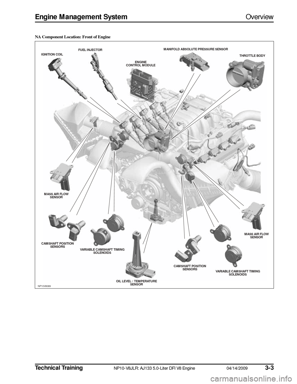
NA Component Location: Front of Engine
NP10V8089
THROTTLE BODY
MANIFOLD ABS
OLUTE PRESSURE S ENSOR
ENGINE
CONTROL MODULE
FUEL INJECTOR
IGNITION COIL
MASS AIR FLOW SENS OR
CAMS HAFT POS ITION
S ENS ORS
VARIABLE CAMS HAFT TIMING
S OLENOIDS
OIL LEVEL / TEMPERATURESENS OR CAMS
HAFT POS ITION
S ENS ORS
VARIABLE CAMSHAFT TIMING
S OLENOIDS MASS AIR FLOW
SENS OR
Page 7 of 36

Technical Training
NP10-V8JLR: AJ133 5.0-Liter DFI V8 Engine 04/14/2009
3-5
Engine Management System
Overview
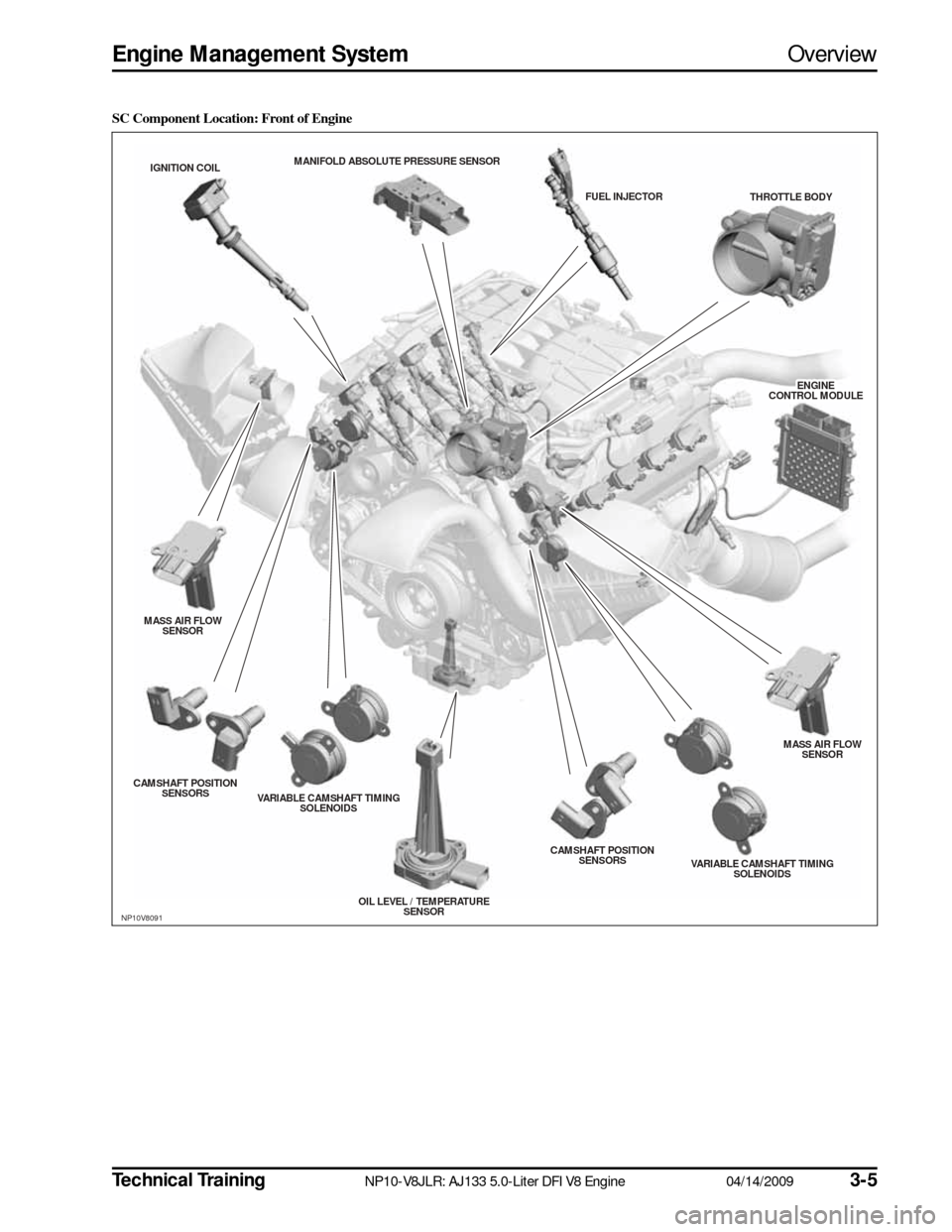
SC Component Location: Front of Engine
NP10V8091
THROTTLE BODY
MANIFOLD ABS
OLUTE PRESSURE S ENSOR
ENGINE
ENGINECONTROL MODULECONTROL MODULEENGINE
CONTROL MODULE
FUEL INJECTOR
IGNITION COIL
MASS AIR FLOW SENS OR
CAMS HAFT POS ITION
S ENS ORS
VARIABLE CAMS HAFT TIMING
S OLENOIDS
OIL LEVEL / TEMPERATURESENS OR CAMS
HAFT POS ITION
S ENS ORS
VARIABLE CAMSHAFT TIMING
S OLENOIDS MASS AIR FLOW
SENS OR
Page 10 of 36

3-8
04/14/2009 NP10-V8JLR: AJ133 5.0-Liter DFI V8 Engine
Technical Training
Engine Control Module
Engine Management System
ENGINE CONTROL MODULE
The ECM is supplied with battery voltage from a 5A fuse and an ignition supply from the ECM relays through\
a 15A
fuse, both located in the CJB. A regulator located within the ECM supplies a 5V current to internal compone\
nts such
as the microprocessor unit. Other components or functions requiring full\
battery voltage are controlled by external
relays or internal switching modules.
The microprocessor within the ECM receives signals from different components and control modules and uses a pro-
gram within the ECM software to interpret the signal information and issue signals which relate t\
o how the engine
components and functions should be controlled. The ECM communicates with other control modules via bidirectional
Controller Area Network (CAN) communication interfaces.
The ECM uses the following inputs and outputs:
Inputs
• Camshaft position (CMP) sensor
• Crankshaft position (CKP) sensor
• Fuel rail high-pressure sensor
• Mass air flow (MAF) sensors (2)
• Knock sensors (4)
• Engine coolant temperature (ECT) sensor
• Manifold absolute pressure (MAP) sensor
• Electronic throttle position sensor
• Accelerator pedal position (APP) sensor
• Cooling fan speed
• Upstream Universal Heated Exhaust Gas Oxygen (UHEGO) sensors (2)
• Brake switch
• Speed control cancel/suspend switch
• Intake air temperature (IAT) sensor (integrated into the MAF) (2)
• Ambient air temperature (AAT) sensor
• Engine oil level and temperature sensor
• Temperature and manifold absolute pressure (TMAP) sensor (SC only)
Outputs
• Throttle Actuator
• Coil-on-plug (COP) ignition coils (8)
• Upstream Universal Heated Exhaust Gas Oxygen (UHEGO) sensors (2)
• Downstream Heated Oxygen Sensors (HO2S) (2)
• Direct injection fuel injectors (8)
• Variable camshaft timing (VCT) solenoids (4)
• Camshaft profile switching (CPS) solenoids (2)
• Intake manifold tuning solenoid
• Carbon canister purge valve
• Fuel pump relay
• Starter relay
• A/C condenser fan relay
• ECM main relay viscous fan control
• Generator control
• Air flap solenoid (SC only)
• Pump control diagnostics
• Diagnostic Monitoring of Tank Leakage (DMTL)
Page 34 of 36

3-3204/14/2009NP10-V8JLR: AJ133 5.0-Liter DFI V8 EngineTechnical Training
Crankcase Ventilation System Engine Management System
CRANKCASE VENTILATION SYSTEM
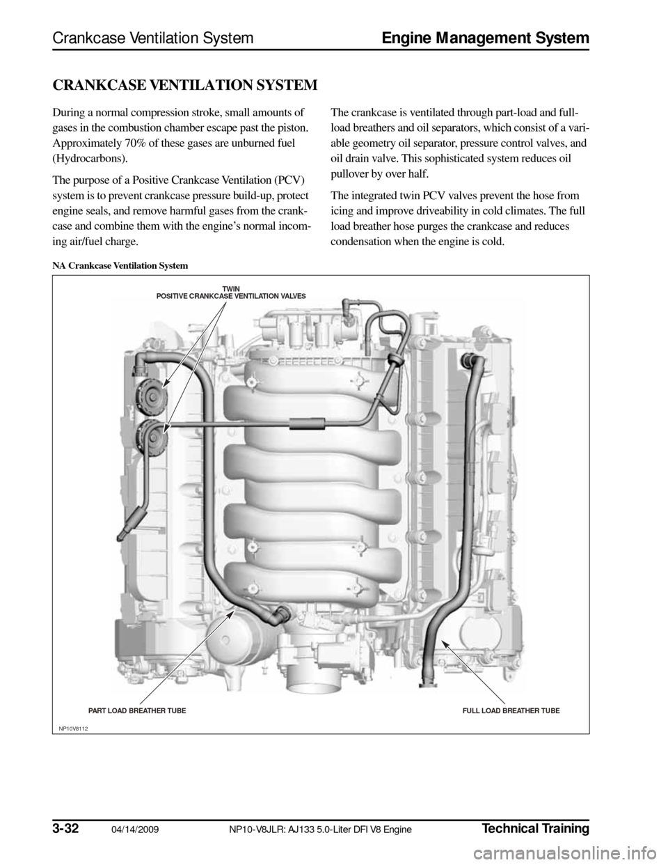
During a normal compression stroke, small amounts of
gases in the combustion chamber escape past the piston.
Approximately 70% of these gases are unburned fuel
(Hydrocarbons).
The purpose of a Positive Crankcase Ventilation (PCV)
system is to prevent crankcase pressure build-up, protect
engine seals, and remove harmful gases from the crank-
case and combine them with the engine’s normal incom-
ing air/fuel charge. The crankcase is ventilated through part-load and full-
load breathers and oil separators, which consist of a vari-
able geometry oil separator, pressure control valves, and
oil drain valve. This sophisticated system reduces oil
pullover by over half.
The integrated twin PCV valves prevent the hose from
icing and improve driveability in cold climates. The full
load breather hose purges the crankcase and reduces
condensation when the engine is cold.
NA Crankcase Ventilation System
TWIN
POS ITIVE CRANKCAS E VENTILATION VALVES
PART LOAD BREATHER TUBE FULL LOAD BREATHER TUBE
NP10V8112