fuse box JAGUAR XF 2009 1.G Lighting In Detail Manual
[x] Cancel search | Manufacturer: JAGUAR, Model Year: 2009, Model line: XF, Model: JAGUAR XF 2009 1.GPages: 12, PDF Size: 0.86 MB
Page 3 of 12

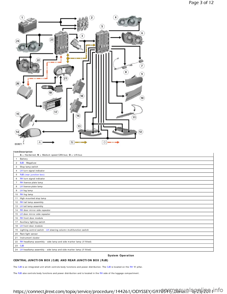
ItemDescription A = Hardwired; N = Medium speed CAN bus; O = LIN bus
Battery
BJB - Megafuse
Stop lamp switch
LH turn signal indicator
RJB (rear junction box)
RH turn signal indicator
RH licence plate lamp
LH licence plate lamp
LH fog lamp
RH fog lamp
High mounted stop lamp
RH tail lamp assembly
LH tail lamp assembly
RH door mirror side repeater
LH door mirror side repeater
RH front door module
Auxiliary lighting switch
LH front door module
Lighting control switch - LH steering column multifunction switch
Rain/light sensor
Instrument cluster
RH headlamp assembly - side lamp and side marker lamp (if fitted)
CJB
LH headlamp assembly - side lamp and side marker lamp (if fitted)
System Operation
CENTRAL JUNCTION BOX (CJB) AND REAR JUNCTION BOX (RJB)
The CJB is an integrated unit which controls body functions and power distribution. The CJB is located on the RH 'A' pillar.
The RJB also controls body functions and power distribution and is located in the RH
side of the luggage compartment.
1
2
3
4
5
6
7
8
9
10
11
12
13
14
15
16
17
18
19
20
21
22
23
24
Page 3 of 12
6/25/2011 https://connect.jlrext.com/topix/service/procedure/144261/ODYSSEY/G970541/,DanaI...
Page 4 of 12

Central Junction Box
The CJB receives inputs from the following switches via the instrument cluster and the medium speed CAN bus:
LH Steering column multifunction switch
- Side lamp position
- Headlamp position
- Automatic (AUTO) position
- Timer delay positions
- Turn signal indicators
- Headlamp flash and main beam positions.
The CJB receives direct inputs from the following components:
Stop lamp switch Rain/light sensor.
The CJB provides power supplies to the following lamps:
LH and RH front side lamps LH and RH front side marker lamps (if fitted) LH and RH static bending lamp (if fitted) LH and RH low beam headlamp LH and RH high beam headlamp.
Rear Junction Box
The RJB provides power supplies to the following lamps:
LH and RH tail lamps LH and RH stop lamps LH and RH front turn signal indicators LH and RH rear turn signal indicators LH and RH licence plate lamps LH and RH side marker lamps High mounted stop lamp Rear fog lamps Reverse lamps.
The RJB also provides a power supply to the LH and RH door modules. The door modules use the power supply to activate the turn signal indicator side repeater lamps located in the door
mirrors, on receipt of a medium speed CAN bus message from the RJB.
Circuit Protection
The CJB and the RJB provide circuit protection for their respective lighting circuits. The exterior lighting circuits are protected by Field Effect Transistors (FET's). The FET's can detect
overloads and short circuits and respond to heat generated by increased current flow caused by a short circuit.
On a normal conventionally protected circuit this would cause a fuse to blow. The FET's respond to the heat increase and disconnect the power supply to the affected circuit. When the fault
is rectified or the FET has cooled, the FET will reset and operate the circuit normally. If the fault persists the FET will cycle, disconnecting and reconnecting the power supply.
The CJB and the RJB store fault codes which can be retrieved using a Jaguar approved diagnostic system. The fault code will identify that there is a fault on a particular output circuit which
will assist with fault diagnosis and detection.
Alarm Indications
The exterior lighting system is used for alarm arm and disarm requests to show alarm system status.
When the driver locks and arms the vehicle, a visual indication of a successful lock and arm request is displayed to the driver by a single flash of the hazard flashers. If the vehicle is
superlocked, then the hazard flashers will flash a second time (200 ms off and 200 ms on) to confirm the superlock request.
If the alarm is activated, the hazard flashers are operated for 10, 30 second cycles of 200 ms on and 200 ms off, with a 10 second delay between each cycle.
• NOTE: On North American Specification (NAS) vehicles, the delay between the cycle when the alarm is activated is 60 seconds.
Lights on Warning
When the ignition is in the off power mode 0 or accessory power mode 4 and the lighting control switch is in the side lamp or headlamp position, a warning chime will sound if the driver's
door is opened. This indicates to the driver that the exterior lights have been left switched on.
The chime is generated from the instrument cluster sounder on receipt of a lights on signal, a driver's door open signal and an ignition off power mode 0 or accessory power mode 4 signal
via a medium speed CAN bus signal from the CJB.
Headlamp Timer
The RJB controls the headlamp timer function which allows the headlamps to remain on for a period of time after leaving the vehicle. This is a driver convenience feature which illuminates
the driveway after leaving the vehicle.
To operate the timer function the lighting control switch must be in one of the three headlamp timer positions when the ignition status is changed from ignition on power mode 6 to the off
power mode 0. The timer function will then be initiated and the low beam headlamps will be illuminated for the selected timer period.
• NOTE: If the lighting switch is in the AUTO position, the headlamp timer will not function when the ignition is changed to off power mode 0.
When the lighting control switch is in the autolamp exit delay position, the lighting control switch reference voltage flows through 4 of the resistors. The returned signal voltage is detected
by the instrument cluster which outputs a message on the medium speed CAN bus to the RJB that autolamps has been selected.
Depending on the selected exit delay position, the reference voltage to the autolamp exit delay switch is routed through 3, 2 or 1 resistors which is detected by the instrument cluster. The
cluster outputs a message on the medium speed CAN bus to the RJB that autolamp exit delay period has been selected at 30, 60 or 120 seconds respectively.
Crash Signal Activation
Page 4 of 12
6/25/2011 https://connect.jlrext.com/topix/service/procedure/144261/ODYSSEY/G970541/,DanaI...