change wheel JAGUAR XF 2009 1.G Owners Manual
[x] Cancel search | Manufacturer: JAGUAR, Model Year: 2009, Model line: XF, Model: JAGUAR XF 2009 1.GPages: 391, PDF Size: 19.32 MB
Page 13 of 391
13
Introduction
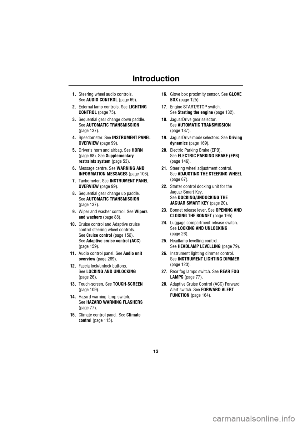
1.Steering wheel audio controls.
See AUDIO CONTROL (page 69).
2. External lamp controls. See LIGHTING
CONTROL (page 75).
3. Sequential gear change down paddle.
See AUTOMATIC TRANSMISSION
(page 137).
4. Speedometer. See INSTRUMENT PANEL
OVERVIEW (page 99).
5. Driver’s horn and airbag. See HORN
(page 68). See Supplementary
restraints system (page 53).
6. Message centre. See WARNING AND
INFORMATION MESSAGES (page 106).
7. Tachometer. See INSTRUMENT PANEL
OVERVIEW (page 99).
8. Sequential gear change up paddle.
See AUTOMATIC TRANSMISSION
(page 137).
9. Wiper and washer control. See Wipers
and washers (page 88).
10. Cruise control and Adaptive cruise
control steering wheel controls.
SeeCruise control (page 156).
See Adaptive cruise control (ACC)
(page 159).
11. Audio control panel. See Audio unit
overview (page 269).
12. Fascia lock/unlock buttons.
SeeLOCKING AND UNLOCKING
(page 26).
13. Touch-screen. See TOUCH-SCREEN
(page 109).
14. Hazard warning lamp switch.
SeeHAZARD WARNING FLASHERS
(page 77).
15. Climate contro l panel. SeeClimate
control (page 115). 16.
Glove box proximity sensor. See GLOVE
BOX (page 125).
17. Engine START/STOP switch.
SeeStarting the engine (page 132).
18. JaguarDrive gear selector.
SeeAUTOMATIC TRANSMISSION
(page
137).
19. JaguarDrive mode selectors. See Driving
dynamics (page 169).
20. Electric Parking Brake (EPB).
SeeELECTRIC PARKIN G BRAKE (EPB)
(page 146).
21. Steering wheel adju stment control.
See ADJUSTING THE STEERING WHEEL
(page 67).
22. Starter control docking unit for the
Jaguar Smart Key.
SeeDOCKING/UNDOCKING THE
JAGUAR SMART KEY (page 20).
23. Bonnet release lever. See OPENING AND
CLOSING THE BONNET (page 195).
24. Luggage compartment release switch.
SeeLOCKING AND UNLOCKING
(page 26).
25. Headlamp levelling control.
SeeHEADLAMP LEVELLING (page 79).
26. Instrument lighting dimmer control.
SeeINSTRUMENT LIGHTING DIMMER
(page 123).
27. Rear fog lamps switch. See REAR FOG
LAMPS (page 77).
28. Adaptive Cruise Control (ACC) Forward
Alert switch. See FORWARD ALERT
FUNCTION (page 164).
Page 70 of 391
Steering wheel
70
Activating the system
To activate voice control, press the voice
button on the steering wheel. A tone will be
heard and LISTENING will be displayed in the
message centre, to indicate that the system is
now waiting for a voice command.
Note: It is only necessary to press the voice
button at the beginning of each voice session.
Language and accent
Voice feedback is give n in the same language
as is set for Voice recognition. For example, if
the Voice recognition language is set to UK
English, the system wi ll not recognise other
languages (e.g. US English). The language for
the system can be changed using the
touch-screen as follows:
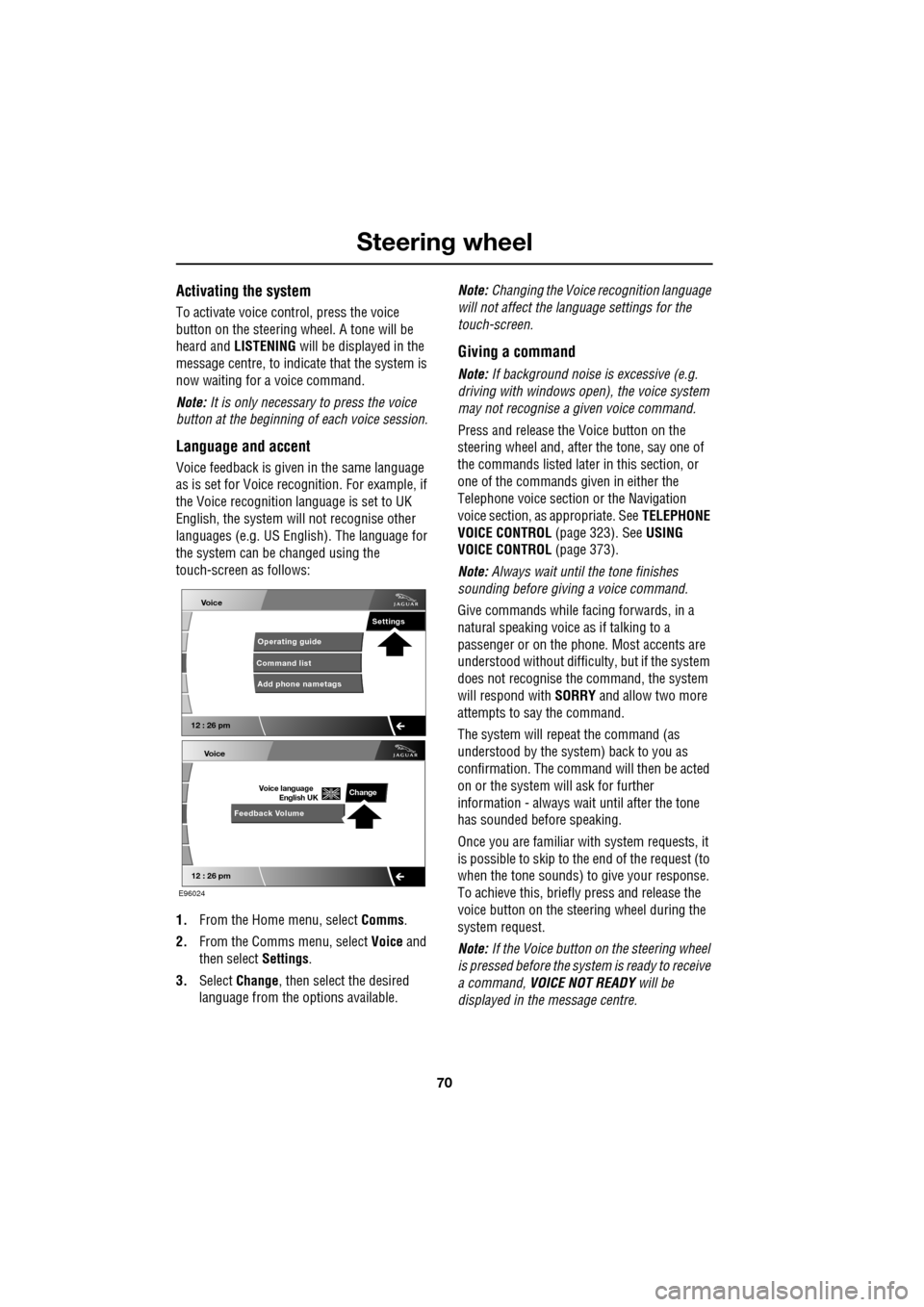
1. From the Home menu, select Comms.
2. From the Comms menu, select Voice and
then select Settings.
3. Select Change, then select the desired
language from the options available. Note:
Changing the Voice recognition language
will not affect the language settings for the
touch-screen.
Giving a command
Note: If background noise is excessive (e.g.
driving with windows open), the voice system
may not recognise a given voice command.
Press and release the Voice button on the
steering wheel and, after the tone, say one of
the commands listed later in this section, or
one of the commands given in either the
Telephone voice section or the Navigation
voice section, as appropriate. See TELEPHONE
VOICE CONTROL (page 323). SeeUSING
VOICE CONTROL (page 373).
Note: Always wait until the tone finishes
sounding before giving a voice command.
Give commands while facing forwards, in a
natural speaking voice as if talking to a
passenger or on the phon e. Most accents are
understood without difficul ty, but if the system
does not recognise the command, the system
will respond with SORRY and allow two more
attempts to say the command.
The system will repe at the command (as
understood by the system ) back to you as
confirmation. The comma nd will then be acted
on or the system will ask for further
information - always wait until after the tone
has sounded before speaking.
Once you are familiar with system requests, it
is possible to skip to the end of the request (to
when the tone sounds) to give your response.
To achieve this, briefly press and release the
voice button on the steering wheel during the
system request.
Note: If the Voice button on the steering wheel
is pressed before the system is ready to receive
a command, VOICE NOT READY will be
displayed in the message centre.
Voice
12 : 26 pm
Add phone nametags
Command list Operating guide
Settings
E96024
Voice
12 : 26 pm
Feedback Volume
Voice language
English UKChange
Page 91 of 391
91
Wipers and washers
CHANGING THE WIPER BLADES
Service position
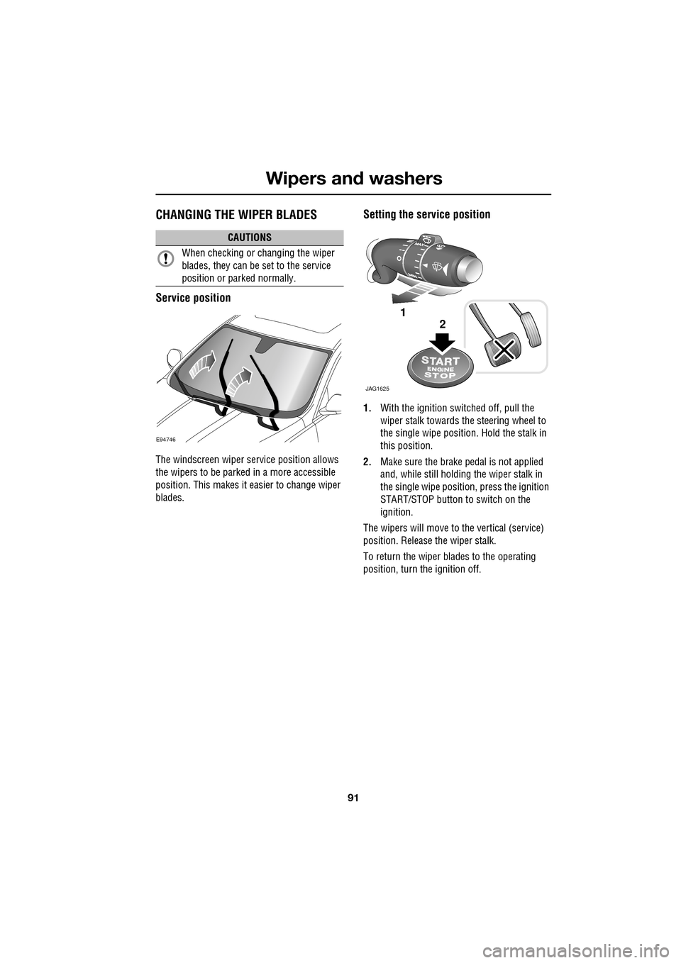
The windscreen wiper service position allows
the wipers to be parked in a more accessible
position. This makes it easier to change wiper
blades.
Setting the service position
1.With the ignition switched off, pull the
wiper stalk towards the steering wheel to
the single wipe position. Hold the stalk in
this position.
2. Make sure the brake pedal is not applied
and, while still holding the wiper stalk in
the single wipe positi on, press the ignition
START/STOP button to switch on the
ignition.
The wipers will move to the vertical (service)
position. Release the wiper stalk.
To return the wiper blades to the operating
position, turn the ignition off.
CAUTIONS
When checking or changing the wiper
blades, they can be set to the service
position or parked normally.
E94746
JAG1625
1
2
Page 97 of 391
97
Windows and mirrors
BLIND SPOT MONITOR
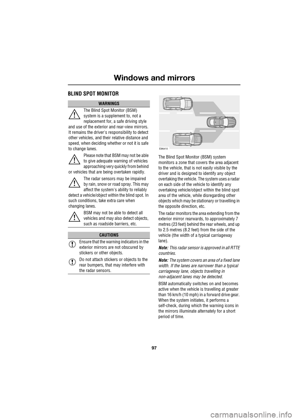
The Blind Spot Monitor (BSM) system
monitors a zone that covers the area adjacent
to the vehicle, that is not easily visible by the
driver and is designed to identify any object
overtaking the vehicle. Th e system uses a radar
on each side of the vehicle to identify any
overtaking vehicl e/object within the blind spot
area of the vehicle, while disregarding other
objects which may be stati onary or travelling in
the opposite direction, etc.
The radar monitors the ar ea extending from the
exterior mirror rearwards, to approximately 7
metres (23 feet) behind the rear wheels, and up
to 2.5 metres (8.2 feet) from the side of the
vehicle (the wi dth of a typical carriageway
lane).
Note: This radar sensor is approved in all RTTE
countries.
Note: The system covers an area of a fixed lane
width. If the lanes are narrower than a typical
carriageway lane, objects travelling in
non-adjacent lanes may be detected.
BSM automatically switches on and becomes
active when the vehicle is travelling at greater
than 16 km/h (10 mph) in a forward drive gear.
When the system initiates, it performs a
self-check, during which the warning icons in
the mirrors illuminate alternately for a short
period of time.
WARNINGS
The Blind Spot Monitor (BSM)
system is a supplement to, not a
replacement for, a safe driving style
and use of the exterior and rear-view mirrors.
It remains the driver's re sponsibility to detect
other vehicles, and their relative distance and
speed, when deciding whet her or not it is safe
to change lanes.
Please note that BSM may not be able
to give adequate wa rning of vehicles
approaching very quickly from behind
or vehicles that are be ing overtaken rapidly.
The radar sensors may be impaired
by rain, snow or road spray. This may
affect the sy stem's ability to reliably
detect a vehicle/object wi thin the blind spot. In
such conditions, take extra care when
changing lanes.
BSM may not be able to detect all
vehicles and may also detect objects,
such as roadside barriers, etc.
CAUTIONS
Ensure that the warning indicators in the
exterior mirrors are not obscured by
stickers or other objects.
Do not attach stickers or objects to the
rear bumpers, that may interfere with
the radar sensors.
E96410
Page 115 of 391
115
Climate control
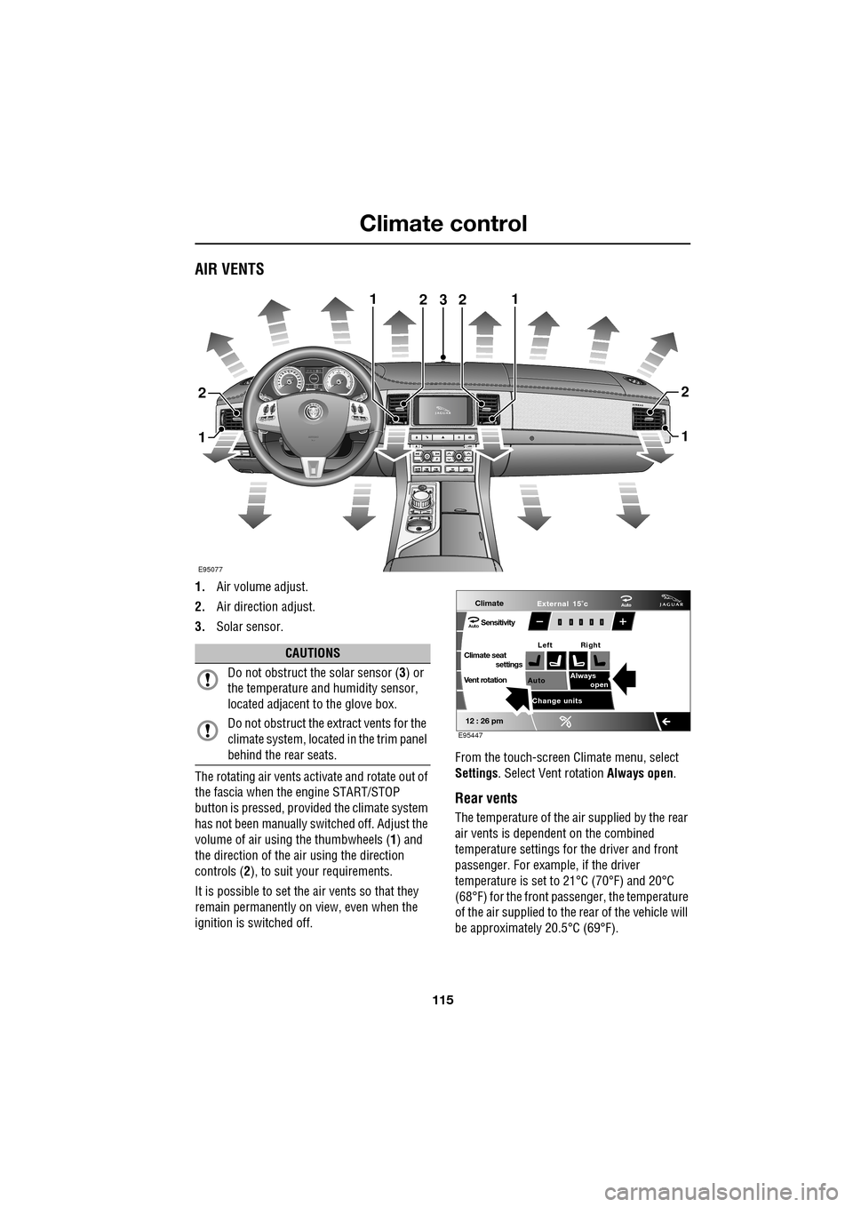
AIR VENTS
1.Air volume adjust.
2. Air direction adjust.
3. Solar sensor.
The rotating air vents acti vate and rotate out of
the fascia when the engine START/STOP
button is pressed, provided the climate system
has not been manually switched off. Adjust the
volume of air usi ng the thumbwheels ( 1) and
the direction of the air using the direction
controls ( 2), to suit your requirements.
It is possible to set the air vents so that they
remain permanently on view, even when the
ignition is switched off. From the touch-screen Climate menu, select
Settings
. Select Vent rotation Always open .
Rear vents
The temperature of the air supplied by the rear
air vents is dependent on the combined
temperature settings for the driver and front
passenger. For example, if the driver
temperature is set to 21°C (70°F) and 20°C
(68°F) for the front passenger, the temperature
of the air supplied to the rear of the vehicle will
be approximately 20.5°C (69°F).
AkI t F1 k
E95077
11
1
23
2
1
2
2
CAUTIONS
Do not obstruct the solar sensor ( 3) or
the temperature a nd humidity sensor,
located adjacent to the glove box.
Do not obstruct the extract vents for the
climate system, located in the trim panel
behind the rear seats.
Climate
SensitivityAuto
Climate seat settings
Vent rotation
12 : 26 pm
Auto Always
open
Change units External 15˚c
Left Right
Auto
E95447
Page 142 of 391
Transmission
142
Note: When the transmission is set to
permanent manual mode (i.e. using the
paddles to change gear while in Sport mode)
and Dynamic mode is selected, transmission
up-shifts are fully controlled by the driver. This
means that the transmissi on will not change up
a gear automatically, even when the vehicle's
rev limit is reached. When the rev limit is
reached, the gear position indicator in the
message centre will glow amber, to indicate
that the next gear should be selected.
To exit from the Jaguar Sequential Shift
permanent manual mode, either pull and hold
the shift-up paddle for approximately one
second (to return directly to automatic
operation in S ), or rotate the gear selector to
the D position. The transmission will revert to
the D automatic shift mode.
Manual operation
To shift-up, briefly pull the shift-up ( +) paddle
on the right-hand side of the steering wheel
towards you.
To shift-down, briefly pull the shift-down
paddle ( -) on the left-hand side of the steering
wheel towards you.
The message centre display will change to
highlight the requested gear.
Note: The transmission will inhibit up-shifts
and down-shifts if the requested shift would
result in an engine speed outside the normal
operating range of the engine. If this occurs,
the message centre will briefly display the
requested gear selection, but will return to
displaying the current gear.
The Jaguar Sequential Shift mode also has the
following features: Kick-down:
Operation of kick-down in Jaguar
Sequential Shift mode will override the
currently selected gear. The lowest available
gear will be selected for maximum acceleration
and will be highlighted in the message centre
display. Subsequent manu al shifts may then be
selected as usual.
Positive torque: Provides throttle blips on
down-shifts, improving shift feel and response.
Shift assist: The transmission will
automatically up-shift at the engine speed
redline in Jaguar Sequential Shift mode, as if
commanded manually.
The transmission will automatically
down-shift, when the engine speed drops too
low for the currently selected gear.
When the vehicle approaches, or comes to
rest, second gear is au tomatically selected.
Subsequent pull-aways will occur in second
gear, unless the accelerator pedal demand is
high or a down-shift is manually selected, in
which case, first gear will be selected.
In all cases the message centre will display the
current gear.
Note: During sustained braking, if a down-shift
is selected at a speed which would result in the
engine speed exceeding its normal operating
range, the gear change wi ll be indicated in the
message centre, but the down-shift will be
delayed until the vehi cle speed has reduced
sufficiently for the gear selection to be made,
without causing the engine speed to exceed its
normal operating range.
Page 161 of 391
161
Adaptive cruise control (ACC)
The vehicle will then maintain the constant time
gap to the vehicle ahead until:
•The vehicle ahead accelerates to a speed
above the set speed.
• The vehicle ahead moves out of lane or out
of view.
• A new gap distance is set.
If necessary, the vehicle brakes will be
automatically applied to slow the vehicle to
maintain the gap to the vehicle in front.
The maximum braking which is applied by the
ACC system is limited and can be overridden by
the driver applying the brakes, if required.
Note: Driver braking will cancel ACC.
If the ACC system predicts that its maximum
braking level will not be sufficient, then an
audible warning will sound while the ACC
continues to brake. DRIVER INTERVENE will be
displayed on the message centre. The driver
should take immediate action.
When in follow mode, the vehicle will
automatically return to the set speed when the
road ahead is clear, for instance when:
• The vehicle in front accelerates or changes
lane.
• The driver changes lane to either side or
enters an exit lane.
The driver should intervene if appropriate.
Changing the follow mode set gap
The gap from the vehicle ahead can be
decreased or increased by rolling the
thumbwheel on the stee ring wheel. Four gap
settings are available and the selected gap
setting will be displaye d on the message centre
when either ACC button is pressed. Each gap level is indicated by an
additional
chevron in front of th e vehicle icon in the
message centre (one chevron (gap level 1)
being the shortest, four chevrons (gap level 4)
being the longest). A fter the ignition is
switched on, the default gap (gap level 3) will
be automatically selected ready for ACC
operation.
Note: When the ignition is switched off, the
gap setting will revert to the default setting
(gap level 3) when switched on again.
Note: It is the driver’s responsibility to select a
gap appropriate to the driving conditions.
Overriding the speed and follow mode
The set speed and gap ca n be overridden by
pressing the accelerator pedal when cruising at
constant speed or in follow mode. If the vehicle
is in follow mode, the instrument warning
indicator will go out when the ACC is
overridden by the driver using the accelerator
and CRUISE OVERRIDE will be displayed on
the message centre. When the accelerator is
released the ACC functi on will operate again
and vehicle speed will decrease to the set
speed, or a lower spee d if follow mode is
active.
WARNING
Whenever the driver is overriding the
ACC by depressing the accelerator
pedal, the ACC will not automatically
apply the brakes to ma intain separation from
any vehicle ahead.
Page 170 of 391
Driving dynamics
170
DYNAMIC MODE
(V8 petrol and diesel vehicles only)
Press to operate. Dynamic mode
co-ordinates the vehicle's control
systems to deliver a high
performance driving experience. This setting
enhances key vehicle systems so that the
vehicle's full potential can be exploited. The
vehicle's responses are aimed at involving the
driver more in focused and purposeful driving,
helping swift progress.
Note: When the transmission is set to
permanent manual mode (i.e. using the
paddles to change gear while in Sport mode)
and Dynamic mode is selected, transmission
upshifts are fully controlled by the driver. This
means that the transmissi on will not change up
a gear automatically, even when the vehicle's
rev limit is reached. When the rev limit is
reached, the gear position indicator in the
message centre will glow amber, to indicate
that the next gear should be selected.
Note: Dynamic mode cannot be active at the
same time as Winter m ode. Dynamic mode will
remain selected for approximately six hours
after the ignition is swit ched off, after which
point it will need to be reselected if required.
STABILITY CONTROL
Dynamic Stability Control (DSC)
Dynamic Stability Contro l (DSC) is operational
whenever the engine is running, unless it has
been manually switched off. When the system
is operating, the warn ing indicator in the
instrument panel will flash.
The DSC system controls the Anti-lock Braking
System (ABS), traction control and yaw control
of the vehicle.
The DSC system assists the driver in retaining
directional control of th e vehicle in situations
where the vehicle is sliding (understeer or
oversteer). It must not encourage the driver to
drive beyond the limit of adhesion or at speeds
higher than those suitable for the prevailing
road and traffic conditions.
DSC applies braking pres sure to individual
wheels if excessive variation is detected. This
ensures that the vehicle follows the driver’s
intended direction of travel as closely as
possible.
Traction control will intervene to control wheel
spin by automatically reducing the power
output from the engine and applying braking to
individual wheels. This improves acceleration,
particularly on surfaces with uneven friction
(e.g. one wheel on ice with another on tarmac).
Note: For recommended DSC mode selection,
refer to the JaguarDri ve Control scenarios
section in this handbook.
WARNING
The fact that the vehicle is fitted with
DSC, must never allow the driver to
be tempted into taking risks which
could affect his or her sa fety or that of other
road users. In all cases, it remains the driver’s
responsibility to drive sa fely according to the
prevailing conditions.
Page 219 of 391
219
Wheels and tyres
The following procedure should be used to
check and adjust the tyres pressures.
1.Remove the valve cap.
2. Firmly attach a tyre pressure gauge/inflator
to the valve.
3. Read the tyre pressure from the gauge,
and add air if required.
4. If air is added to the tyre, remove the gauge
and re-attach it be fore reading the
pressure. Failure to do so may result in an
inaccurate reading.
5. If the tyre pressure is too high, remove the
gauge and allow air out of the tyre by
pressing the centre of the valve. Refit the
gauge to the valve and check the pressure.
6. Repeat the process a dding or removing air
as required until the correct tyre pressure
is reached.
7. Refit the valve cap.
Note: It is an offence in certain countries to
drive a vehicle with incorrect tyre pressures.
Note: It is the driver's responsibility to ensure
that the tyre pressures are correct.
Tyre valves
Keep the valve caps screwed down firmly to
prevent water or dirt entering the valve. Check
the valves for leaks when checking the tyre
pressures.
Pressure compensation for ambient
temperature changes
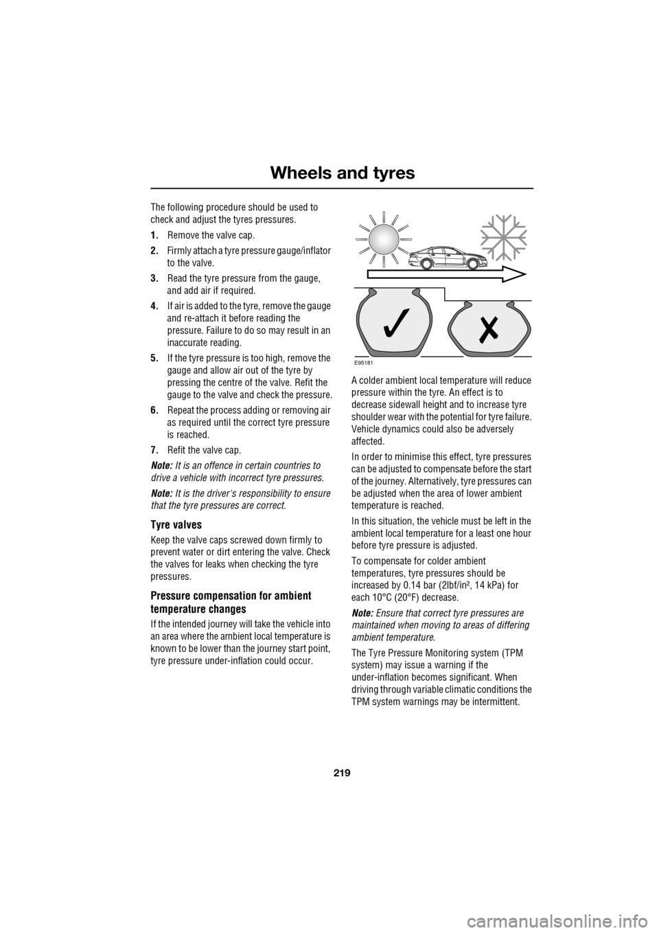
If the intended journey will take the vehicle into
an area where the ambien t local temperature is
known to be lower than the journey start point,
tyre pressure under-i nflation could occur. A colder ambient local temperature will reduce
pressure within the tyre. An effect is to
decrease sidewall height
and to increase tyre
shoulder wear with the potential for tyre failure.
Vehicle dynamics could also be adversely
affected.
In order to minimise this effect, tyre pressures
can be adjusted to compensate before the start
of the journey. Alternatively, tyre pressures can
be adjusted when the area of lower ambient
temperature is reached.
In this situation, the vehicle must be left in the
ambient local temperature for a least one hour
before tyre pressu re is adjusted.
To compensate for colder ambient
temperatures, tyre pressures should be
increased by 0.14 bar (2lbf/in², 14 kPa) for
each 10°C (20°F) decrease.
Note: Ensure that correct tyre pressures are
maintained when moving to areas of differing
ambient temperature.
The Tyre Pressure M onitoring system (TPM
system) may issue a warning if the
under-inflation becomes significant. When
driving through variable climatic conditions the
TPM system warnings may be intermittent.
E95181
Page 221 of 391
221
Wheels and tyres
Wear indicators
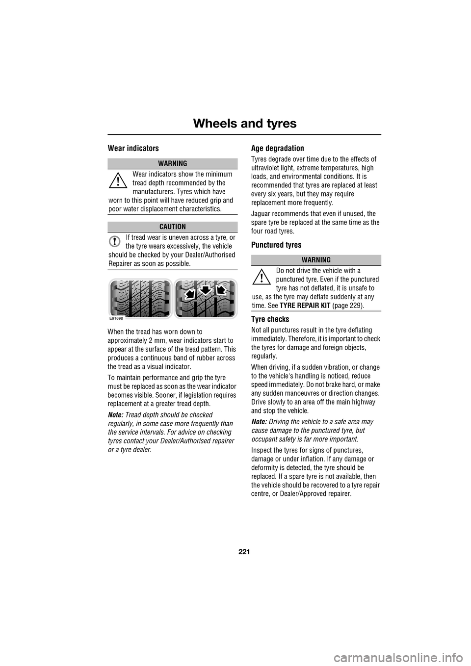
When the tread has worn down to
approximately 2 mm, wear indicators start to
appear at the surface of the tread pattern. This
produces a continuous band of rubber across
the tread as a visual indicator.
To maintain performance and grip the tyre
must be replaced as soon as the wear indicator
becomes visible. Sooner, if legislation requires
replacement at a greater tread depth.
Note: Tread depth should be checked
regularly, in some case more frequently than
the service intervals. For advice on checking
tyres contact your Dealer/Authorised repairer
or a tyre dealer.
Age degradation
Tyres degrade over time due to the effects of
ultraviolet light, extreme temperatures, high
loads, and environmen tal conditions. It is
recommended that tyres are replaced at least
every six years, but they may require
replacement more frequently.
Jaguar recommends that even if unused, the
spare tyre be replaced at the same time as the
four road tyres.
Punctured tyres
Tyre checks
Not all punctures result in the tyre deflating
immediately. Therefore, it is important to check
the tyres for damage and foreign objects,
regularly.
When driving, if a sudden vibration, or change
to the vehicle's hand ling is noticed, reduce
speed immediately. Do not brake hard, or make
any sudden manoeuvres or direction changes.
Drive slowly to an area off the main highway
and stop the vehicle.
Note: Driving the vehicle to a safe area may
cause damage to th e punctured tyre, but
occupant safety is far more important.
Inspect the tyres for signs of punctures,
damage or under inflati on. If any damage or
deformity is detected, the tyre should be
replaced. If a spare tyre is not available, then
the vehicle should be reco vered to a tyre repair
centre, or Dealer/Approved repairer.
WARNING
Wear indicators show the minimum
tread depth recommended by the
manufacturers. Tyres which have
worn to this point will have reduced grip and
poor water displacement characteristics.
CAUTION
If tread wear is uneve n across a tyre, or
the tyre wears excessively, the vehicle
should be checked by your Dealer/Authorised
Repairer as soon as possible.
E91698
WARNING
Do not drive the vehicle with a
punctured tyre. Even if the punctured
tyre has not deflated, it is unsafe to
use, as the tyre may deflate suddenly at any
time. See TYRE REPAIR KIT (page 229).