fuel filter JAGUAR XFR 2010 1.G Workshop Manual
[x] Cancel search | Manufacturer: JAGUAR, Model Year: 2010, Model line: XFR, Model: JAGUAR XFR 2010 1.GPages: 3039, PDF Size: 58.49 MB
Page 11 of 3039

Overview
System Operation and Component DescriptionDiagnosis and TestingEngineGeneral ProceduresEngine Oil Draining and Filling
Engine Oil Vacuum Draining and Filling
Fuel Pump Camshaft Timing Check
Fuel Pump Camshaft Timing Adjustment
Valve Clearance Check
Valve Clearance AdjustmentRemoval and InstallationCamshaft LH
Camshaft RH
Crankshaft Front Seal
Crankshaft Pulley
Crankshaft Rear Seal
Cylinder Head LH
Cylinder Head RH
Engine Mount LH
Engine Mount RH
Exhaust Manifold LH
Exhaust Manifold RH
Flexplate
Oil Cooler
Oil Filter Element
Oil Pan
Oil Pan Extension
Oil Pump
Timing Cover
Timing Drive Components
Valve Cover LH
Valve Cover RH
Cylinder Block Oil Gallery Plug
Fuel Pump Camshaft - Assembly Part Number: INA Timing Drive
Fuel Pump Camshaft - Assembly Part Number: Tsubaki Timing Drive
Lower Timing Cover
ValvesRemovalEngineInstallationEngine
Page 15 of 3039

Catalyst Monitor Sensor RH
Crankshaft Position (CKP) Sensor
Engine Control Module (ECM)
Engine Coolant Temperature (ECT) Sensor
Engine Oil Level Sensor
Front Knock Sensor (KS) LH
Front Knock Sensor (KS) RH
Fuel Rail Pressure (FRP) Sensor
Heated Oxygen Sensor (HO2S) LH
Heated Oxygen Sensor (HO2S) RH
Manifold Absolute Pressure (MAP) Sensor
Mass Air Flow (MAF) Sensor
Rear Knock Sensor (KS) LH
Rear Knock Sensor (KS) RH
Variable Valve Timing (VVT) Oil Control Solenoid LH
Variable Valve Timing (VVT) Oil Control Solenoid RH307: Automatic Transmission/Transaxle
307-01B: Automatic Transmission/Transaxle - TDV6 3.0L Diesel /V8 5.0L Petrol/V8 S/C 5.0L
PetrolSpecificationDescription and OperationComponent Location
Overview
System Operation and Component DescriptionDiagnosis and TestingDiagnosticsGeneral ProceduresTransmission Fluid Level Check
Transmission Fluid Drain and RefillRemoval and InstallationInput Shaft Seal
Extension Housing Seal
Transmission Control Module (TCM) and Main Control Valve Body
Transmission Fluid Pan, Gasket and Filter
Transmission Support Insulator - V8 5.0L Petrol/V8 S/C 5.0L Petrol
Transmission, Transmission Fluid Cooler and Transmission Fluid Cooler Tubes - V8 5.0L Petrol/V8
S/C 5.0L Petrol
Transmission and Transmission Fluid Cooler - V8 5.0L Petrol/V8 S/C 5.0L PetrolRemovalTransmission - V8 5.0L Petrol/V8 S/C 5.0L PetrolInstallationTransmission - V8 5.0L Petrol/V8 S/C 5.0L Petrol
Page 64 of 3039

Viton
In common with many other manufacturers' vehicles, some components installed to the Jaguar range have 'O' rings, seals or
gaskets which contain a material known as 'Viton'.
Viton is a fluoroelastomer, that is a synthetic rubber type which contains Fluorine. It is commonly used for 'O' rings, gaskets
and seals of all types. Although Viton is the most well known fluoroelastomer, there are others, including Fluorel and
Tecmoflon.
When used under design conditions fluoroelastomers are perfectly safe. If, however, they are exposed to temperatures in
excess of 400º C, the material will not burn, but will decompose, and one of the products formed is hydrofluoric acid.
This acid is extremely corrosive and may be absorbed directly, through contact, into the body.
'O' rings, seals or gaskets which have been exposed to very high temperatures will appear charred or as a black sticky
substance.
DO NOT, under any circumstances touch them or the attached components.
Enquiries should be made to determine whether Viton or any other fluoroelastomer has been used in the affected 'O' ring, seal
or gasket. If they are of natural rubber or nitrile there is no hazard. If in doubt, be cautious and assume that the material may
be Viton or any fluoroelastomer.
If Viton or any other fluoroelastomers have been used, the affected area should be decontaminated before the commencement
of work.
Disposable heavy duty plastic gloves should be worn at all times, and the affected area washed down using wire wool and a
limewater (calcium hydroxide) solution to neutralize the acid before disposing of the decomposed Viton residue and final
cleaning of the area. After use, the plastic gloves should be discarded carefully and safely.
Welding
See also Fire, Electric Shock, Gas Cylinders.
Welding processes include Resistance Welding (Spot Welding), Arc Welding and Gas Welding (and cutting).
Resistance Welding (Spot Welding)
This process may cause particles of molten metal to be emitted at a high velocity, and the eyes and skin must be protected.
Arc Welding
This process emits a high level of ultraviolet radiation which may cause arc-eye and skin burns to the operator and to other
persons nearby. Gas-shielded welding processes are particularly hazardous in this respect. Personal protection must be worn,
and screens used to shield other people.
CONTACT LENS WEARERS ARE ADVISED TO REVERT TO ORDINARY SPECTACLES WHEN ARC WELDING as the arc spectrum is
believed to emit microwaves which dry out the fluid between the lens and the eye. This may result in blindness when the lens
is removed from the eye.
Metal spatter will also occur, and appropriate eye and skin protection is necessary.
The heat of the welding arc will produce fumes and gases from the metals being welded, the rods and from any applied
coatings or contamination on the surfaces being worked on. These gases and fumes may be toxic and inhalation of these
should be avoided. The use of extraction ventilation to remove the fumes from the working area may be necessary particularly
in cases where the general ventilation is poor, or where considerable welding work is anticipated. In extreme cases or confined
spaces where adequate ventilation cannot be provided, air-fed respirators may be necessary.
Gas Welding (and Cutting)
Oxy-acetylene torches may be used for welding and cutting, and special care must be taken to prevent leakage of these gases,
with consequent risk of fire and explosion.
The process will produce metal spatter and eye and skin protection is necessary.
The flame is bright, and eye protection should be used, but the ultraviolet emission is much less than that from arc welding,
and lighter filters may be used.
The process itself produces few toxic fumes, but such fumes and gases may be produced from coatings on the work,
particularly during cutting away of damaged body parts, and inhalation of the fumes should be avoided.
In brazing, toxic fumes may be produced from the metals in the brazing rod, and a severe hazard may arise if brazing rods
containing cadmium are used. In this event particular care must be taken to avoid inhalation of fumes and expert advice may
be required.
SPECIAL PRECAUTIONS MUST BE TAKEN BEFORE ANY WELDING OR CUTTING TAKES PLACE ON VESSELS WHICH HAVE
CONTAINED COMBUSTIBLE MATERIALS, E.G. BOILING OR STEAMING OUT OF FUEL TANKS.
Warning Symbols on Vehicles
Decals showing warning symbols will be found on various vehicle components.
Page 816 of 3039

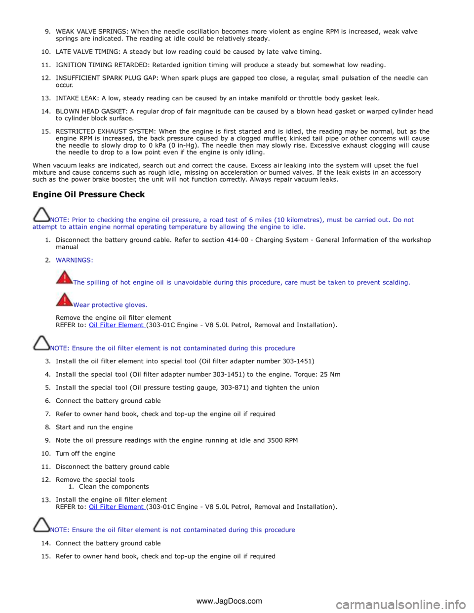
9. WEAK VALVE SPRINGS: When the needle oscillation becomes more violent as engine RPM is increased, weak valve
springs are indicated. The reading at idle could be relatively steady.
10. LATE VALVE TIMING: A steady but low reading could be caused by late valve timing.
11.
IGNITION TIMING RETARDED: Retarded ignition timing will produce a steady but somewhat low reading.
12.
INSUFFICIENT SPARK PLUG GAP: When spark plugs are gapped too close, a regular, small pulsation of the needle can
occur.
13. INTAKE LEAK: A low, steady reading can be caused by an intake manifold or throttle body gasket leak.
14.
BLOWN HEAD GASKET: A regular drop of fair magnitude can be caused by a blown head gasket or warped cylinder head
to cylinder block surface.
15.
RESTRICTED EXHAUST SYSTEM: When the engine is first started and is idled, the reading may be normal, but as the
engine RPM is increased, the back pressure caused by a clogged muffler, kinked tail pipe or other concerns will cause
the needle to slowly drop to 0 kPa (0 in-Hg). The needle then may slowly rise. Excessive exhaust clogging will cause
the needle to drop to a low point even if the engine is only idling.
When vacuum leaks are indicated, search out and correct the cause. Excess air leaking into the system will upset the fuel
mixture and cause concerns such as rough idle, missing on acceleration or burned valves. If the leak exists in an accessory
such as the power brake booster, the unit will not function correctly. Always repair vacuum leaks.
Engine Oil Pressure Check
NOTE: Prior to checking the engine oil pressure, a road test of 6 miles (10 kilometres), must be carried out. Do not
attempt to attain engine normal operating temperature by allowing the engine to idle.
1. Disconnect the battery ground cable. Refer to section 414-00 - Charging System - General Information of the workshop
manual
2. WARNINGS:
The spilling of hot engine oil is unavoidable during this procedure, care must be taken to prevent scalding.
Wear protective gloves.
Remove the engine oil filter element
REFER to: Oil Filter Element (303-01C Engine - V8 5.0L Petrol, Removal and Installation).
NOTE: Ensure the oil filter element is not contaminated during this procedure
3. Install the oil filter element into special tool (Oil filter adapter number 303-1451)
4. Install the special tool (Oil filter adapter number 303-1451) to the engine. Torque: 25 Nm
5. Install the special tool (Oil pressure testing gauge, 303-871) and tighten the union
6. Connect the battery ground cable
7. Refer to owner hand book, check and top-up the engine oil if required
8. Start and run the engine
9. Note the oil pressure readings with the engine running at idle and 3500 RPM
10.
Turn off the engine
11.
Disconnect the battery ground cable
12. Remove the special tools
1. Clean the components
13.
Install the engine oil filter element
REFER to: Oil Filter Element (303-01C Engine - V8 5.0L Petrol, Removal and Installation).
NOTE: Ensure the oil filter element is not contaminated during this procedure
14.
Connect the battery ground cable
15. Refer to owner hand book, check and top-up the engine oil if required
www.JagDocs.com
Page 845 of 3039

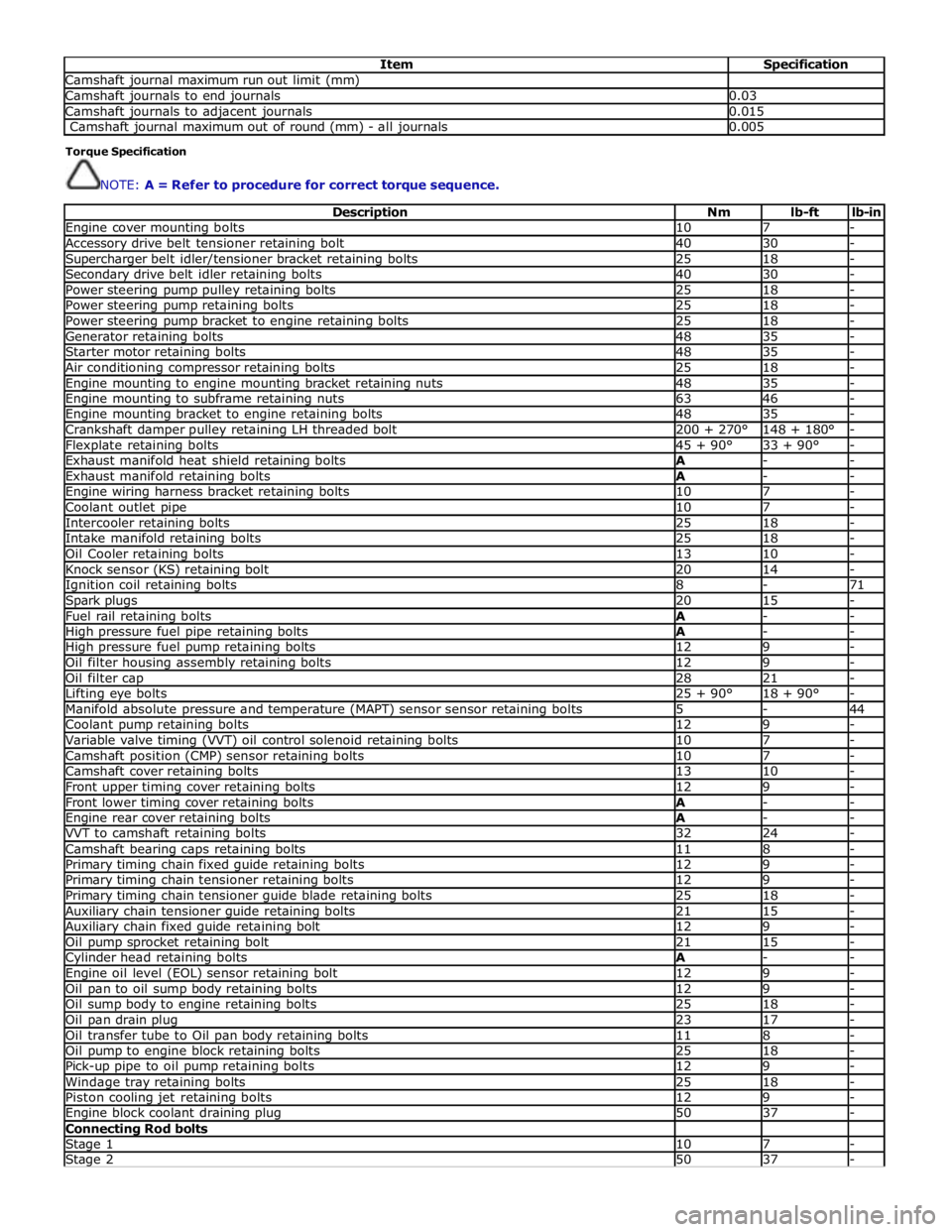
Item Specification Camshaft journal maximum run out limit (mm) Camshaft journals to end journals 0.03 Camshaft journals to adjacent journals 0.015 Camshaft journal maximum out of round (mm) - all journals 0.005 Torque Specification
NOTE: A = Refer to procedure for correct torque sequence.
Description Nm lb-ft lb-in Engine cover mounting bolts 10 7 - Accessory drive belt tensioner retaining bolt 40 30 - Supercharger belt idler/tensioner bracket retaining bolts 25 18 - Secondary drive belt idler retaining bolts 40 30 - Power steering pump pulley retaining bolts 25 18 - Power steering pump retaining bolts 25 18 - Power steering pump bracket to engine retaining bolts 25 18 - Generator retaining bolts 48 35 - Starter motor retaining bolts 48 35 - Air conditioning compressor retaining bolts 25 18 - Engine mounting to engine mounting bracket retaining nuts 48 35 - Engine mounting to subframe retaining nuts 63 46 - Engine mounting bracket to engine retaining bolts 48 35 - Crankshaft damper pulley retaining LH threaded bolt 200 + 270° 148 + 180° - Flexplate retaining bolts 45 + 90° 33 + 90° - Exhaust manifold heat shield retaining bolts A - - Exhaust manifold retaining bolts A - - Engine wiring harness bracket retaining bolts 10 7 - Coolant outlet pipe 10 7 - Intercooler retaining bolts 25 18 - Intake manifold retaining bolts 25 18 - Oil Cooler retaining bolts 13 10 - Knock sensor (KS) retaining bolt 20 14 - Ignition coil retaining bolts 8 - 71 Spark plugs 20 15 - Fuel rail retaining bolts A - - High pressure fuel pipe retaining bolts A - - High pressure fuel pump retaining bolts 12 9 - Oil filter housing assembly retaining bolts 12 9 - Oil filter cap 28 21 - Lifting eye bolts 25 + 90° 18 + 90° - Manifold absolute pressure and temperature (MAPT) sensor sensor retaining bolts 5 - 44 Coolant pump retaining bolts 12 9 - Variable valve timing (VVT) oil control solenoid retaining bolts 10 7 - Camshaft position (CMP) sensor retaining bolts 10 7 - Camshaft cover retaining bolts 13 10 - Front upper timing cover retaining bolts 12 9 - Front lower timing cover retaining bolts A - - Engine rear cover retaining bolts A - - VVT to camshaft retaining bolts 32 24 - Camshaft bearing caps retaining bolts 11 8 - Primary timing chain fixed guide retaining bolts 12 9 - Primary timing chain tensioner retaining bolts 12 9 - Primary timing chain tensioner guide blade retaining bolts 25 18 - Auxiliary chain tensioner guide retaining bolts 21 15 - Auxiliary chain fixed guide retaining bolt 12 9 - Oil pump sprocket retaining bolt 21 15 - Cylinder head retaining bolts A - - Engine oil level (EOL) sensor retaining bolt 12 9 - Oil pan to oil sump body retaining bolts 12 9 - Oil sump body to engine retaining bolts 25 18 - Oil pan drain plug 23 17 - Oil transfer tube to Oil pan body retaining bolts 11 8 - Oil pump to engine block retaining bolts 25 18 - Pick-up pipe to oil pump retaining bolts 12 9 - Windage tray retaining bolts 25 18 - Piston cooling jet retaining bolts 12 9 - Engine block coolant draining plug 50 37 - Connecting Rod bolts Stage 1 10 7 - Stage 2 50 37 -
Page 1058 of 3039

Engine - V8 S/C 5.0L Petrol - Valve Cover LH
Removal and Installation Published: 11-May-2011
Removal
NOTE: Removal steps in this procedure may contain installation details.
1. Refer to: Battery Disconnect and Connect (414-01 Battery, Mounting and Cables, General Procedures).
2. Refer to: Supercharger (303-12D Intake Air Distribution and Filtering - V8 S/C 5.0L Petrol, Removal and Installation).
3. Refer to: Secondary Bulkhead Panel LH - TDV6 3.0L Diesel /V8 5.0L Petrol/V8 S/C 5.0L Petrol (501-02 Front End Body Panels, Removal and Installation).
4. Refer to: Air Cleaner Outlet Pipe LH (303-12D Intake Air Distribution and Filtering - V8 S/C 5.0L Petrol, Removal and Installation).
5. Refer to: Fuel Rail LH (303-04E Fuel Charging and Controls - V8 S/C 5.0L Petrol, Removal and Installation).
6. Torque: 10 Nm 303-1446
Valve Cover Alignment Tool Special Tool(s)
Page 1061 of 3039

Engine - V8 S/C 5.0L Petrol - Valve Cover RH
Removal and Installation Published: 11-May-2011
Removal
NOTE: Removal steps in this procedure may contain installation details.
1. Refer to: Battery Disconnect and Connect (414-01 Battery, Mounting and Cables, General Procedures).
2. Refer to: Supercharger (303-12D Intake Air Distribution and Filtering - V8 S/C 5.0L Petrol, Removal and Installation).
3. Refer to: Secondary Bulkhead Panel RH - TDV6 3.0L Diesel /V8 5.0L Petrol/V8 S/C 5.0L Petrol (501-02 Front End Body Panels, Removal and Installation).
4. Refer to: Air Cleaner Outlet Pipe RH (303-12D Intake Air Distribution and Filtering - V8 S/C 5.0L Petrol, Removal and Installation).
5. Refer to: Fuel Rail RH (303-04E Fuel Charging and Controls - V8 S/C 5.0L Petrol, Removal and Installation).
6. NOTE: Some variation in the illustrations may occur, but
the essential information is always correct. 303-1446
Valve Cover Alignment Tool Special Tool(s) www.JagDocs.com
Page 1188 of 3039

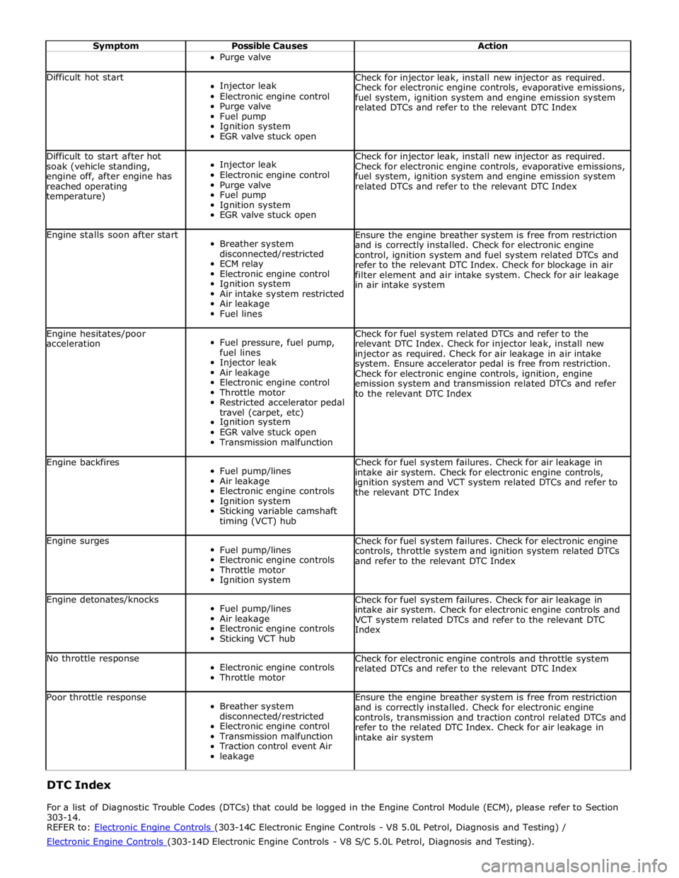
Symptom Possible Causes Action Purge valve
Difficult hot start
Injector leak
Electronic engine control
Purge valve
Fuel pump
Ignition system
EGR valve stuck open Check for injector leak, install new injector as required.
Check for electronic engine controls, evaporative emissions,
fuel system, ignition system and engine emission system
related DTCs and refer to the relevant DTC Index Difficult to start after hot
soak (vehicle standing,
engine off, after engine has
reached operating
temperature)
Injector leak
Electronic engine control
Purge valve
Fuel pump
Ignition system
EGR valve stuck open Check for injector leak, install new injector as required.
Check for electronic engine controls, evaporative emissions,
fuel system, ignition system and engine emission system
related DTCs and refer to the relevant DTC Index Engine stalls soon after start
Breather system
disconnected/restricted
ECM relay
Electronic engine control
Ignition system
Air intake system restricted
Air leakage
Fuel lines Ensure the engine breather system is free from restriction
and is correctly installed. Check for electronic engine
control, ignition system and fuel system related DTCs and
refer to the relevant DTC Index. Check for blockage in air
filter element and air intake system. Check for air leakage
in air intake system Engine hesitates/poor
acceleration
Fuel pressure, fuel pump,
fuel lines
Injector leak
Air leakage
Electronic engine control
Throttle motor
Restricted accelerator pedal
travel (carpet, etc)
Ignition system
EGR valve stuck open
Transmission malfunction Check for fuel system related DTCs and refer to the
relevant DTC Index. Check for injector leak, install new
injector as required. Check for air leakage in air intake
system. Ensure accelerator pedal is free from restriction.
Check for electronic engine controls, ignition, engine
emission system and transmission related DTCs and refer
to the relevant DTC Index Engine backfires
Fuel pump/lines
Air leakage
Electronic engine controls
Ignition system
Sticking variable camshaft
timing (VCT) hub Check for fuel system failures. Check for air leakage in
intake air system. Check for electronic engine controls,
ignition system and VCT system related DTCs and refer to
the relevant DTC Index Engine surges
Fuel pump/lines
Electronic engine controls
Throttle motor
Ignition system Check for fuel system failures. Check for electronic engine
controls, throttle system and ignition system related DTCs
and refer to the relevant DTC Index Engine detonates/knocks
Fuel pump/lines
Air leakage
Electronic engine controls
Sticking VCT hub Check for fuel system failures. Check for air leakage in
intake air system. Check for electronic engine controls and
VCT system related DTCs and refer to the relevant DTC
Index No throttle response
Electronic engine controls
Throttle motor Check for electronic engine controls and throttle system
related DTCs and refer to the relevant DTC Index Poor throttle response
Breather system
disconnected/restricted
Electronic engine control
Transmission malfunction
Traction control event Air
leakage Ensure the engine breather system is free from restriction
and is correctly installed. Check for electronic engine
controls, transmission and traction control related DTCs and
refer to the related DTC Index. Check for air leakage in
intake air system DTC Index
For a list of Diagnostic Trouble Codes (DTCs) that could be logged in the Engine Control Module (ECM), please refer to Section
303-14.
REFER to: Electronic Engine Controls (303-14C Electronic Engine Controls - V8 5.0L Petrol, Diagnosis and Testing) / Electronic Engine Controls (303-14D Electronic Engine Controls - V8 S/C 5.0L Petrol, Diagnosis and Testing).
Page 1203 of 3039

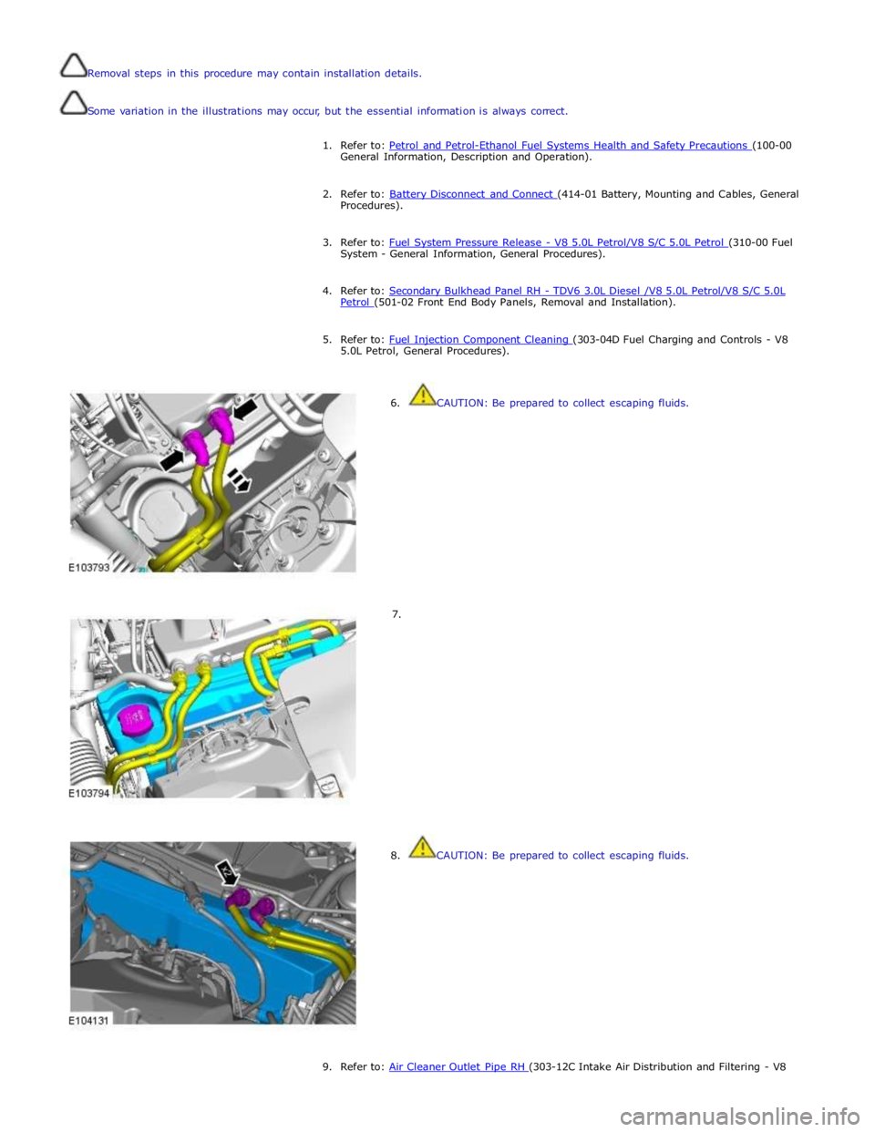
Removal steps in this procedure may contain installation details.
Some variation in the illustrations may occur, but the essential information is always correct.
1. Refer to: Petrol and Petrol-Ethanol Fuel Systems Health and Safety Precautions (100-00 General Information, Description and Operation).
2. Refer to: Battery Disconnect and Connect (414-01 Battery, Mounting and Cables, General Procedures).
3. Refer to: Fuel System Pressure Release - V8 5.0L Petrol/V8 S/C 5.0L Petrol (310-00 Fuel System - General Information, General Procedures).
4. Refer to: Secondary Bulkhead Panel RH - TDV6 3.0L Diesel /V8 5.0L Petrol/V8 S/C 5.0L Petrol (501-02 Front End Body Panels, Removal and Installation).
5. Refer to: Fuel Injection Component Cleaning (303-04D Fuel Charging and Controls - V8 5.0L Petrol, General Procedures).
6. CAUTION: Be prepared to collect escaping fluids.
7.
8. CAUTION: Be prepared to collect escaping fluids.
9. Refer to: Air Cleaner Outlet Pipe RH (303-12C Intake Air Distribution and Filtering - V8
Page 1277 of 3039

Symptom Possible Causes Action Difficult hot start
Injector leak
Electronic engine control
Purge valve
Fuel pump
Ignition system
EGR valve stuck open Check for injector leak, install new injector as required.
Check for electronic engine controls, evaporative emissions,
fuel system, ignition system and engine emission system
related DTCs and refer to the relevant DTC Index Difficult to start after hot
soak (vehicle standing,
engine off, after engine has
reached operating
temperature)
Injector leak
Electronic engine control
Purge valve
Fuel pump
Ignition system
EGR valve stuck open Check for injector leak, install new injector as required.
Check for electronic engine controls, evaporative emissions,
fuel system, ignition system and engine emission system
related DTCs and refer to the relevant DTC Index Engine stalls soon after start
Breather system
disconnected/restricted
ECM relay
Electronic engine control
Ignition system
Air intake system restricted
Air leakage
Fuel lines Ensure the engine breather system is free from restriction
and is correctly installed. Check for electronic engine
control, ignition system and fuel system related DTCs and
refer to the relevant DTC Index. Check for blockage in air
filter element and air intake system. Check for air leakage
in air intake system Engine hesitates/poor
acceleration
Fuel pressure, fuel pump,
fuel lines
Injector leak
Air leakage
Electronic engine control
Throttle motor
Restricted accelerator pedal
travel (carpet, etc)
Ignition system
EGR valve stuck open
Transmission malfunction Check for fuel system related DTCs and refer to the
relevant DTC Index. Check for injector leak, install new
injector as required. Check for air leakage in air intake
system. Ensure accelerator pedal is free from restriction.
Check for electronic engine controls, ignition, engine
emission system and transmission related DTCs and refer
to the relevant DTC Index Engine backfires
Fuel pump/lines
Air leakage
Electronic engine controls
Ignition system
Sticking variable camshaft
timing (VCT) hub Check for fuel system failures. Check for air leakage in
intake air system. Check for electronic engine controls,
ignition system and VCT system related DTCs and refer to
the relevant DTC Index Engine surges
Fuel pump/lines
Electronic engine controls
Throttle motor
Ignition system Check for fuel system failures. Check for electronic engine
controls, throttle system and ignition system related DTCs
and refer to the relevant DTC Index Engine detonates/knocks
Fuel pump/lines
Air leakage
Electronic engine controls
Sticking VCT hub Check for fuel system failures. Check for air leakage in
intake air system. Check for electronic engine controls and
VCT system related DTCs and refer to the relevant DTC
Index No throttle response
Electronic engine controls
Throttle motor Check for electronic engine controls and throttle system
related DTCs and refer to the relevant DTC Index Poor throttle response
Breather system
disconnected/restricted
Electronic engine control
Transmission malfunction
Traction control event Air
leakage Ensure the engine breather system is free from restriction
and is correctly installed. Check for electronic engine
controls, transmission and traction control related DTCs and
refer to the related DTC Index. Check for air leakage in
intake air system DTC Index
For a list of Diagnostic Trouble Codes (DTCs) that could be logged in the Engine Control Module (ECM), please refer to Section
303-14. REFER to:
Electronic Engine Controls (303-14C Electronic Engine Controls - V8 5.0L Petrol, Diagnosis and Testing), Electronic Engine Controls (303-14D Electronic Engine Controls - V8 S/C 5.0L Petrol, Diagnosis and Testing).