abs module JAGUAR XFR 2010 1.G Owners Manual
[x] Cancel search | Manufacturer: JAGUAR, Model Year: 2010, Model line: XFR, Model: JAGUAR XFR 2010 1.GPages: 3039, PDF Size: 58.49 MB
Page 1948 of 3039
3 Satellite Radio digital receiver (Optional - NAS only) 4 Telephone control module (Optional) 5 Touch-screen 6 TV tuner (Optional) 7 Power amplifier (Not fitted to the Jaguar Sound System) 8 IAM (integrated audio module) 9 Portable audio module (Optional) 10 ICM (information control module)
AUDIO SYSTEM OPERATION System Operation
The components of the audio/infotainment system are all connected on the MOST (media orientated systems transport) ring.
The MOST (media orientated systems transport) ring is a fibre optic communications bus for multimedia applications. Audio
and control information is passed around the MOST (media orientated systems transport) ring and can be picked up by any of
the systems units. For example, radio station tuning/selection input by the vehicle user into the Touch-screen is sent along the
MOST (media orientated systems transport) ring and collected by the IAM (integrated audio module) which then selects the
requested radio station.
MOST (media orientated systems transport) technology uses a plastic optical fibre which forms a network connecting the audio
and multimedia system components. Each component in the ring is connected to the plastic optical fibre through a device
known as a FOT (fibre optical transceiver). Each FOT (fibre optical transceiver) has two optical connections; one connection is
sensitive to light and is the input, the second connection forms the light source and is the output. The system operates by
connecting the output from one FOT (fibre optical transceiver) to the input of another FOT (fibre optical transceiver).
The light signals are sent in one direction only and are formed in the following way:
Electrical signals are converted into an electrical current
The current then drives an LED (light emitting diode) in the FOT (fibre optical transceiver) to produce a high intensity
red light
The LED transmits the light through a fibre optic cable A photo diode in the FOT (fibre optical transceiver) at the opposite end of the fibre optic cable detects the light.
The following components may be connected to the MOST ring dependant on the vehicle equipment level:
IAM (integrated audio module)
Touch-screen
ICM (information control module)
DAB (digital audio broadcasting) radio receiver (Optional - Europe only)
Satellite radio digital receiver (Optional - NAS only)
Power amplifier (Not fitted to the Jaguar Sound System)
Portable audio module (Optional)
Telephone control module (Optional)
Navigation computer (Optional)
TV tuner (Optional)
NOTE: Do not view the red light directly
MOST is a synchronous network. A timing master supplies the clock information and all other devices on the network
synchronize their operation to this clock. The timing master for the MOST (media orientated systems transport) network on this
vehicle is the ICM (information control module). This unit also controls and manages the MOST (media orientated systems
transport) ring and the system components.
An Optical Bus tester is used in conjunction with the Jaguar diagnostic system to diagnose the MOST (media orientated
systems transport) system. The Optical Bus tester emits a visible, high intensity red light which can be connected into the ring
at any point to test the ring integrity. Disconnecting a MOST (media orientated systems transport) connector will reveal if the
high intensity red light is visible.
If a break occurs in the MOST (media orientated systems transport) ring fault codes are stored in the ICM (information control
module) which can be retrieved using the Jaguar diagnostic system equipment.
With reference to the audio system information and signal transfer the instrument cluster is the gateway between the high
and medium speed CAN bus communication protocols. The ICM (information control module) is the gateway between medium speed CAN and the MOST (media orientated systems transport) systems.
A typical example of information transfer is vehicle speed information from the ABS (anti-lock brake system) module used to
control the automatic volume control function. The vehicle speed information from the ABS module is sent on the high speed CAN network and collected by the instrument panel gateway. The signal is passed to the medium speed CAN network and onto the ICM (information control module) gateway. The ICM (information control module) calculates the volume adjustment
required. The corrected audio volume level signal is sent on the MOST (media orientated systems transport) network to the
IAM (integrated audio module) or Power amplifier (dependant on vehicle equipment level) for output to the speaker system.
Page 1949 of 3039
systems.
A typical example of information transfer is vehicle speed information from the ABS (anti-lock brake system) module used to
control the automatic volume control function. The vehicle speed information from the ABS module is sent on the high speed
CAN network and collected by the instrument panel gateway. The signal is passed to the medium speed CAN network and onto the ICM gateway. The ICM calculates the volume adjustment required. The corrected audio volume level signal is sent on the
MOST network to the IAM or Power amplifier (dependant on vehicle equipment level) for output to the speaker system.
AUDIO SYSTEM USER CONTROLS
Touch-Screen
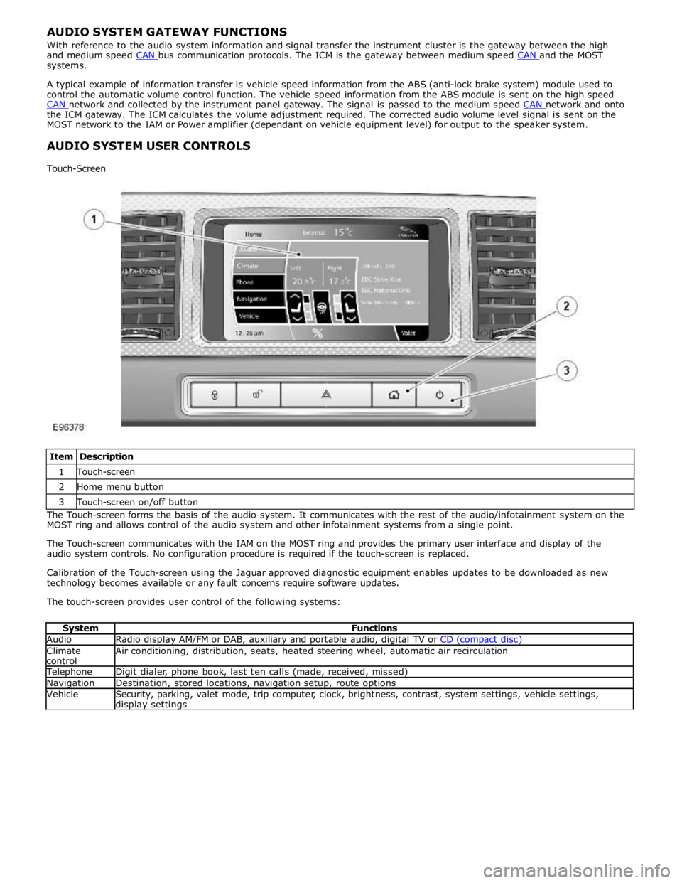
Item Description 1 Touch-screen 2 Home menu button 3 Touch-screen on/off button The Touch-screen forms the basis of the audio system. It communicates with the rest of the audio/infotainment system on the
MOST ring and allows control of the audio system and other infotainment systems from a single point.
The Touch-screen communicates with the IAM on the MOST ring and provides the primary user interface and display of the
audio system controls. No configuration procedure is required if the touch-screen is replaced.
Calibration of the Touch-screen using the Jaguar approved diagnostic equipment enables updates to be downloaded as new
technology becomes available or any fault concerns require software updates.
The touch-screen provides user control of the following systems:
System Functions Audio Radio display AM/FM or DAB, auxiliary and portable audio, digital TV or CD (compact disc) Climate
control Air conditioning, distribution, seats, heated steering wheel, automatic air recirculation Telephone Digit dialer, phone book, last ten calls (made, received, missed) Navigation Destination, stored locations, navigation setup, route options Vehicle
Security, parking, valet mode, trip computer, clock, brightness, contrast, system settings, vehicle settings, display settings
Page 1974 of 3039

Published: 11-May-2011
Information and Entertainment System - Navigation System - System
Operation and Component Description
Description and Operation
Control Diagram
NOTE: A = Hardwired; D = High Speed CAN bus; N = Medium Speed CAN bus; O = LIN bus; P = MOST ring; Q = GVIF; T
= CoAxial
Item Description 1 ABS (anti-lock brake system) module 2 Steering wheel remote audio controls 3 Touch-screen 4 Power amplifier 5 Speakers
Page 1979 of 3039

VICS (vehicle information and communication system) receiver (Japan only)
TMC (traffic message channel) receiver (Europe only)
JaguarVoice control module
The navigation computer contains a solid state piezo gyro which measures the motion of the vehicle around its vertical axis.
The gyro operates on the principle known as the coriolis force. The coriolis force is the force that appears to accelerate a body
moving away from its rotational axis against the direction of rotation of the axis.
Using inputs from the ABS module, the GPS antenna and the gyro sensor, the computer calculates the vehicle's current position, direction and speed.
The navigation computer houses the DVD (digital versatile disc) drive. The drive is used to read map data from region specific
DVD's. The number of DVD's issued per region varies depending on the amount of information available. The regions are as follows:
Europe (2 versions, Western Europe and Whole of Europe)
NAS (North American specification)
Japan, Middle East, Australia and South Africa
A button, located adjacent to the DVD slot, is provided to eject the DVD from the unit. Prior to ejecting the disc the slot protection has to be slid to the side. If the ignition is on, or the entertainment system is in 1-hour mode, one press of the
button will eject the DVD.
The navigation computer uses non-volatile memory to store settings and configuration information when it is powered down.
This process takes place just before the computer turns off.
No configuration procedure is required if the navigation computer is replaced. There is no option to calibrate the navigation
computer using the Jaguar approved diagnostic equipment; however in some regions a software download, contained in the
DVD disc, is required before the navigation system becomes operational.
MICROPHONE
A single microphone is used for hands-free operation using the JaguarVoice system. The microphone has an integrated noise
suppression system for hands-free use. The microphone is a standard directional type and is located in the front roof overhead
console. The microphone is hardwired to the IAM (integrated audio module). When replacing the microphone extra care must be
taken to make sure it is fitted into its securing clips for correct positioning and orientation.
GPS Antenna
The GPS antenna passes signals from the GPS satellites to the navigation computer for processing. The antenna is located in
Page 2033 of 3039
Halogen Low/high Beam Headlamp
The halogen low/high beam headlamp uses a projector lens, similar to the xenon headlamp. The projector module comprises
an ellipsoidal lens and a reflector. The projector reflector collects the light produced by the halogen bulb and projects the light
into a focal plane containing a shield. The contour of the shield is projected onto the road by the lens. The low/high beam
bulbs are quartz halogen and are retained in the headlamp unit with conventional wire retaining clips.
A tourist lever mechanism is located on the right hand side of the projector module. This mechanism moves a flap to blank off
a portion of the beam spread to enable the vehicle to be driven in opposite drive hand markets without applying blanking
decals to the headlamp lens. The beam is changed by removing the access cover at the rear of the lamp assembly and moving
a small lever located near the bulb holder, at the side of the projector.
Halogen High Beam Headlamp - Xenon and Halogen
The xenon and halogen headlamps use a complex surface reflector for the halogen fill in high beam lamp only lighting unit,
which is of the same design on both headlamp types. This type of reflector has the reflector divided into separate parabolic
segments, with each segment having a different focal length.
The high beam headlamp bulbs are quartz halogen and are retained in the headlamp unit with conventional wire retaining
clips.
Cornering Lamps
NOTE: The cornering lamps are not fitted to NAS vehicles.
The cornering lamps are an optional feature designed to illuminate the direction of travel when cornering at low speeds. The
design of the lens projects a spread of light from the vehicle at approximately 45 degrees to the vehicle axis. The cornering
lamp is incorporated into the headlamp assembly and shares the same housing as the low beam headlamp. The cornering lamp
uses a 35W Halogen H8 bulb which is permanently located in an integral holder which is connected on the headlamp housing.
The holder is located in an aperture in the headlamp housing and rotated to lock. The bulb is accessible via a removable cover
on the base of the headlamp housing.
The cornering lamps are controlled by the LH steering column multifunction switch with the lighting control switch in the headlamp position and the ignition in power mode 6. The cornering lamps are supplied power via the ignition circuit to ensure
that they do not function with the headlamp delay feature. The cornering lamps are deactivated if the vehicle speed exceeds
25 mph (40 km/h). Only one cornering lamp will illuminate at any one time. If the left hand turn signal indicators are selected
on, the left hand cornering lamp will be illuminated and vice versa, providing the vehicle speed and lighting control switch
positions are correct.
Static Bending Lamps
NOTE: The static bending lamps are not fitted to NAS vehicles.
The static bending lamps are designed to illuminate the direction of travel when cornering at low speeds. The static bending
lamp functionality, which is controlled by the CJB and the headlamp leveling module, operates using inputs from the steering angle sensor and vehicle speed information from the ABS (anti-lock brake system) module. The static bending lamp is
incorporated into the headlamp assembly and shares the same housing as the low beam headlamp. The design of the lens
projects a spread of light from the vehicle at approximately 45 degrees to the vehicle axis. The static bending lamp uses a
35W Halogen H8 bulb which locates in a holder which is connected via wires to the main connector on the headlamp housing.
The holder is located in an aperture in the headlamp housing and rotated to lock. The bulb is accessible via a removable cover
at the rear of the headlamp housing.
The static bending lamps operate with a steering angle sensor CAN bus signal which is received by the CJB. The CJB monitors this signal and vehicle speed and activates the static bending lamp bulb. When the operation parameters of the lamp are
reached, the CJB fades the static bending lamp bulb on using a PWM (pulse width modulation) voltage over a period of approximately 2 seconds. When the lamp is switched off, the CJB fades the bulb off by decreasing the PWM voltage in a linear manner depending on steering angle and vehicle speed. The cornering lamps can only be active for a maximum of 3 minutes.
NOTE: Static bending lamps only operate when the transmission is in DRIVE or in SPORT.
Turn Signal Indicators
The turn signal indicator lamp is incorporated into the outer part of the headlamp assembly. The turn signal indicator lamp
uses a PY21W bayonet orange colored bulb in ROW markets, a S8W 27/7W wedge bulb is used in NAS markets. The bulb is
fitted into a holder which connects with contacts in the headlamp housing. The holder is fitted into an aperture in the
headlamp housing and rotated to lock into position.
When active, the turn signal indicator lamps will flash at a frequency cycle of 380ms on and 380ms off. If a bulb fails, the
remaining turn signal lamps bulbs continue to flash at normal speed. The turn signal indicators in the instrument cluster will
flash at double speed to indicate the bulb failure to the driver.
Side Lamps
The side lamp is located between the headlamp projector module and the high bean headlamp. The side lamp uses a W5W
wedge fitting bulb which locates in a holder which connected via wires to the main connector on the headlamp housing. The
holder is a push fit into a receptacle in the headlamp housing. The bulb is accessible by removal of the inner cover on the rear
of the headlamp housing. Access to the bulb requires removal of the headlamp from the vehicle. The side lamps are operated
by selecting side lamps or headlamps on the lighting control switch. The side lamps are functional at all times and are
Page 2034 of 3039
dependant on a particular ignition mode status. The side lamps will also be illuminated when the lighting control switch is in
the AUTO position and a 'lights on' signal is received by the CJB from the rain/light sensor Side Marker Lamps (NAS only)
The side marker lamp is located in the outer part of the headlamp assembly. The side marker lamp uses a W5W wedge fitting
bulb. The bulb is fitted into a holder which connects with contacts in the headlamp housing. The holder is fitted into an
aperture which connects with contacts in the headlamp housing. The side marker lamp is active at all times when the side
lamps are active.
AUTOMATIC HEADLAMP OPERATION
The automatic headlamp function is a driver assistance system. The driver can override the system operation by selection of
side lamp or headlamp on if the ambient light conditions require front and rear lighting to be active. The automatic headlamp
system uses a light sensor and the CJB, which are connected via a LIN (local interconnect network) bus to control the headlamp functionality. The light sensor is incorporated in the rain/light sensor located on the inside of the windshield, below
the rear view mirror. The wiper system also uses the rain/light sensor for automatic wiper operation.
The light sensor measures the ambient light around the vehicle in a vertical direction and also the angular light level from the
front of the vehicle. The rain/light sensor uses vehicle speed signals, wiper switch position and the park position of the front
wipers to control the system. The automatic headlamp operation uses ambient light levels which are monitored by photodiode
incorporated in the rain/light sensor. The rain/light sensor sends a lights on/off request to the CJB on the LIN bus, which responds by switching on the low beam headlamps, front side lamps and rear tail lamps. The automatic headlamps are
activated under the following conditions:
Twilight
Darkness
Rain
Snow
Tunnels
Underground or multistoried car parks.
Operation of the automatic headlamps requires the ignition to be in ignition mode 6, the lighting control switch to be in the
'AUTO' position and a lights on request signal from the light sensor. If the rain sensor signal activates the fast speed wipers,
the low beam headlamps are activated, providing the lighting control switch is in the 'AUTO' position.
HEADLAMP LEVELING
Headlamp leveling provides for the adjustment of the vertical aim of the headlamps. The leveling system is primarily required
to minimise glare to other road users when a heavy load is in the rear of the vehicle. Two systems of headlamp leveling are
available; manual and static dynamic.
Manual Headlamp Leveling
The manual system uses a thumbwheel rheostat to adjust the vertical alignment of the headlamps to compensate for differing
vehicle loading. The rotary thumbwheel is located on the auxiliary lighting switch, adjacent to the illumination dimmer
thumbwheel. Three positions are available to adjust the headlamps to a position to prevent glare to other road users.
Static Dynamic Headlamp Leveling
The static dynamic headlamp leveling system uses the following components:
Front and rear vehicle height sensors
Two headlamp leveling, vertical adjustment motors
Headlamp leveling module
Ignition in mode 6
Vehicle speed information from ABS module.
The static dynamic system uses height sensors fitted to the front and rear suspension and a headlamp leveling module which
periodically monitors the vehicle attitude and adjusts the headlamp vertical alignment accordingly.
Static dynamic headlamp leveling is controlled by a headlamp leveling module located in the lower instrument panel, behind
the glovebox.
The height sensors are both located on the RH side of the vehicle. The front sensor is attached to the front suspension lower arm with a strap and to the front sub frame with a bracket and 2 bolts. The rear sensor is attached to the rear suspension
upper control arm with a cable tied clip and to the rear sub frame with a bracket and 2 bolts. Each sensor has 3 connections to
the headlamp leveling module; power, ground and signal.
DAYTIME RUNNING LAMPS (DRL)
Refer to DRL section for details. Refer to: Daytime Running Lamps (DRL) (417-04 Daytime Running Lamps (DRL), Description and Operation).
REAR LAMP ASSEMBLY
The rear lamp assembly is a 2 piece unit, with one part located in the rear quarter panel and the second part attached to the
luggage compartment lid. The outer rear lamp assembly is located in a recess in the vehicle body. The lamp is secured with 2
studs inboard studs on the lamp body which are secured to the vehicle body with 2 nuts. A third outboard stud and nut secures
Page 2060 of 3039
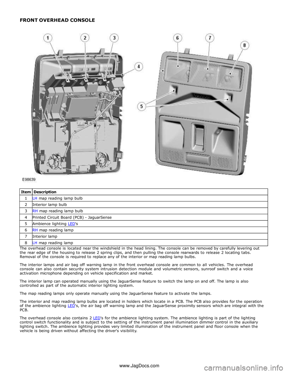
1 LH map reading lamp bulb 2 Interior lamp bulb 3 RH map reading lamp bulb 4 Printed Circuit Board (PCB) - JaguarSense 5 Ambience lighting LED's 6 RH map reading lamp 7 Interior lamp 8 LH map reading lamp The overhead console is located near the windshield in the head lining. The console can be removed by carefully levering out
the rear edge of the housing to release 2 spring clips, and then pulling the console rearwards to release 2 locating tabs.
Removal of the console is required to replace any of the interior or map reading lamp bulbs.
The interior lamps and air bag off warning lamp in the front overhead console are common to all vehicles. The overhead
console can also contain security system intrusion detection module and volumetric sensors, sunroof switch and a voice
activation microphone depending on vehicle specification and market.
The interior lamp can operated manually using the JaguarSense feature to switch the lamp on and off. The lamp is also
controlled as part of the automatic interior lighting system.
The map reading lamps only operate manually using the JaguarSense feature to activate the lamps.
The interior and map reading lamp bulbs are located in holders which locate in a PCB. The PCB also provides for the operation
of the ambience lighting LED's, the air bag off warning lamp and the JaguarSense proximity sensors which are integral with the PCB.
The overhead console also contains 2 LED's for the ambience lighting system. The ambience lighting is part of the lighting control switch functionality and is subject to the setting of the instrument panel illumination dimmer control in the auxiliary
lighting switch. The ambience lighting provides very limited illumination of the instrument panel and floor console when the
vehicle is being driven without affecting the driver's visibility. www.JagDocs.com
Page 2072 of 3039
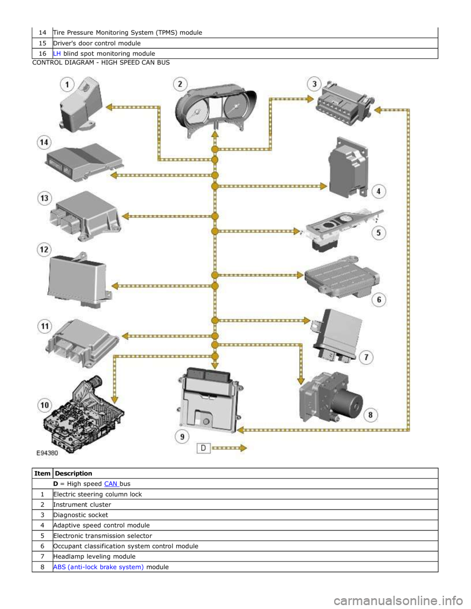
Tire Pressure Monitoring System (TPMS) module 15 Driver's door control module 16 LH blind spot monitoring module CONTROL DIAGRAM - HIGH SPEED CAN BUS
Item Description D = High speed CAN bus 1 Electric steering column lock 2 Instrument cluster 3 Diagnostic socket 4 Adaptive speed control module 5 Electronic transmission selector 6 Occupant classification system control module 7 Headlamp leveling module 8 ABS (anti-lock brake system) module
Page 2142 of 3039
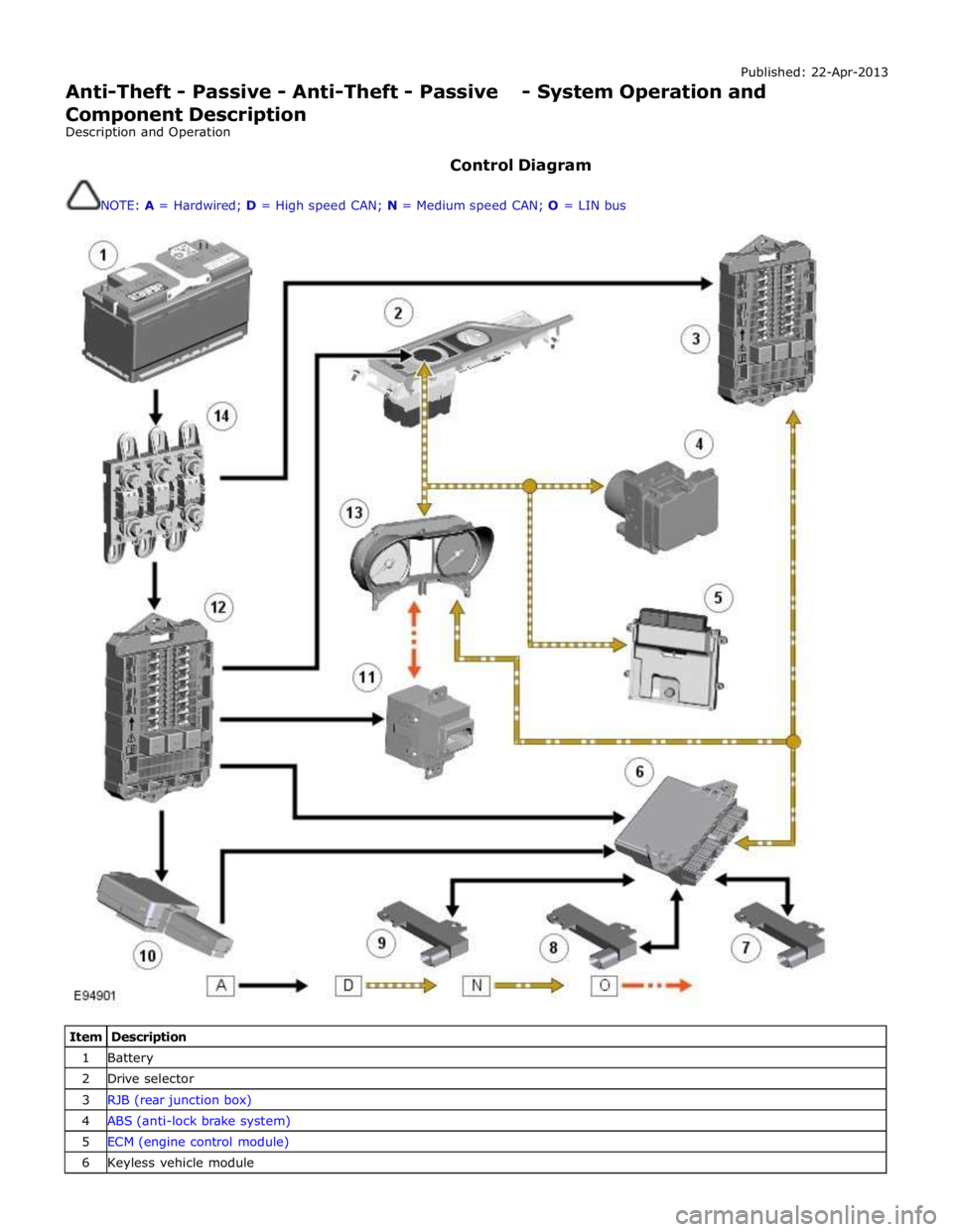
Published: 22-Apr-2013
Anti-Theft - Passive - Anti-Theft - Passive - System Operation and
Component Description
Description and Operation
Control Diagram
NOTE: A = Hardwired; D = High speed CAN; N = Medium speed CAN; O = LIN bus
Item Description 1 Battery 2 Drive selector 3 RJB (rear junction box) 4 ABS (anti-lock brake system) 5 ECM (engine control module) 6 Keyless vehicle module
Page 2143 of 3039
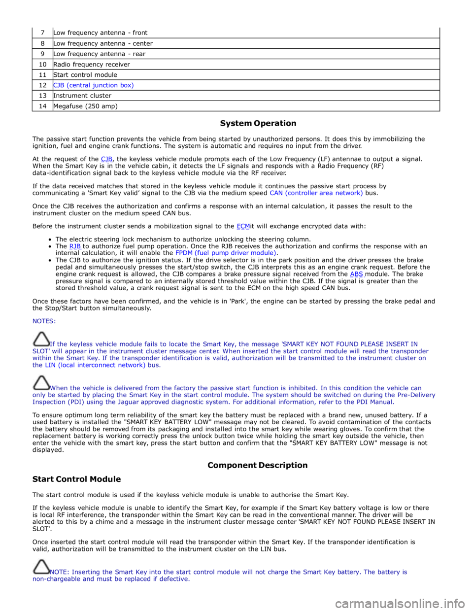
7 Low frequency antenna - front 8 Low frequency antenna - center 9 Low frequency antenna - rear 10 Radio frequency receiver 11 Start control module 12 CJB (central junction box) 13 Instrument cluster 14 Megafuse (250 amp)
System Operation
The passive start function prevents the vehicle from being started by unauthorized persons. It does this by immobilizing the
ignition, fuel and engine crank functions. The system is automatic and requires no input from the driver.
At the request of the CJB, the keyless vehicle module prompts each of the Low Frequency (LF) antennae to output a signal. When the Smart Key is in the vehicle cabin, it detects the LF signals and responds with a Radio Frequency (RF)
data-identification signal back to the keyless vehicle module via the RF receiver.
If the data received matches that stored in the keyless vehicle module it continues the passive start process by
communicating a 'Smart Key valid’ signal to the CJB via the medium speed CAN (controller area network) bus.
Once the CJB receives the authorization and confirms a response with an internal calculation, it passes the result to the
instrument cluster on the medium speed CAN bus.
Before the instrument cluster sends a mobilization signal to the ECMit will exchange encrypted data with: The electric steering lock mechanism to authorize unlocking the steering column.
The RJB to authorize fuel pump operation. Once the RJB receives the authorization and confirms the response with an internal calculation, it will enable the FPDM (fuel pump driver module).
The CJB to authorize the ignition status. If the drive selector is in the park position and the driver presses the brake
pedal and simultaneously presses the start/stop switch, the CJB interprets this as an engine crank request. Before the
engine crank request is allowed, the CJB compares a brake pressure signal received from the ABS module. The brake pressure signal is compared to an internally stored threshold value within the CJB. If the signal is greater than the
stored threshold value, a crank request signal is sent to the ECM on the high speed CAN bus.
Once these factors have been confirmed, and the vehicle is in 'Park', the engine can be started by pressing the brake pedal and
the Stop/Start button simultaneously.
NOTES:
If the keyless vehicle module fails to locate the Smart Key, the message 'SMART KEY NOT FOUND PLEASE INSERT IN
SLOT' will appear in the instrument cluster message center. When inserted the start control module will read the transponder
within the Smart Key. If the transponder identification is valid, authorization will be transmitted to the instrument cluster on
the LIN (local interconnect network) bus.
When the vehicle is delivered from the factory the passive start function is inhibited. In this condition the vehicle can
only be started by placing the Smart Key in the start control module. The system should be switched on during the Pre-Delivery
Inspection (PDI) using the Jaguar approved diagnostic system. For additional information, refer to the PDI Manual.
To ensure optimum long term reliability of the smart key the battery must be replaced with a brand new, unused battery. If a
used battery is installed the "SMART KEY BATTERY LOW" message may not be cleared. To avoid contamination of the contacts
the battery should be removed from its packaging and installed into the smart key while wearing gloves. To confirm that the
replacement battery is working correctly press the unlock button twice while holding the smart key outside the vehicle, then
enter the vehicle with the smart key, press the start button and confirm that the "SMART KEY BATTERY LOW" message is not
displayed.
Start Control Module Component Description
The start control module is used if the keyless vehicle module is unable to authorise the Smart Key.
If the keyless vehicle module is unable to identify the Smart Key, for example if the Smart Key battery voltage is low or there
is local RF interference, the transponder within the Smart Key can be read in the conventional manner. The driver will be
alerted to this by a chime and a message in the instrument cluster message center 'SMART KEY NOT FOUND PLEASE INSERT IN
SLOT'.
Once inserted the start control module will read the transponder within the Smart Key. If the transponder identification is
valid, authorization will be transmitted to the instrument cluster on the LIN bus.
NOTE: Inserting the Smart Key into the start control module will not charge the Smart Key battery. The battery is
non-chargeable and must be replaced if defective.