abs module JAGUAR XFR 2010 1.G Repair Manual
[x] Cancel search | Manufacturer: JAGUAR, Model Year: 2010, Model line: XFR, Model: JAGUAR XFR 2010 1.GPages: 3039, PDF Size: 58.49 MB
Page 744 of 3039

1 Return fluid control groove 2 Radial groove 3 Feed fluid control groove 4 Radial groove 5 Axial groove 6 Feed fluid control edge 7 Feed fluid radial groove 8 Return fluid control edge 9 Return fluid chamber 10 Cut-off valve 11 Radial groove 12 Servotronic transducer valve 13 Feed fluid radial groove 14 Radial groove 15 Orifice 16 Balls 17 Compression spring 18 Torsion bar 19 Power steering fluid reservoir 20 Valve rotor 21 Reaction piston 22 Reaction chamber 23 Centering piece 24 Pressure relief/flow limiting valve 25 Power steering pump 26 Inner tie-rod 27 Pinion 28 Valve sleeve 29 Steering gear rack 30 Steering gear housing 31 Power assist cylinder - right 32 Piston 33 Power assist cylinder - left When the steering wheel is turned to the right, the steering rack and piston moves to the left in the piston bore. The valve
rotor is rotated to the right (clockwise) and pressurized fluid is directed over the further opened feed fluid control edges and to
the associated axial grooves, the radial groove and via an external pipe to the left power assist cylinder chamber. The pressure
applied to the piston from the left power assist cylinder chamber provides the hydraulic assistance.
An adaptable pressure build-up is achieved by the partially or fully closed feed fluid control edges restricting or preventing a
connection between the fluid pressure inlet and the other axial grooves connected to the radial groove.
Simultaneously, the fluid pressure outlet to the pressurized axial grooves are restricted or partially restricted by the closing
return fluid control edges. The fluid displaced by the piston from the right power assist cylinder chamber, flows through an
external pipe to the radial grooves. From there the fluid passes to the associated axial grooves and on to the return fluid
control grooves, via the further opened return fluid control edges.
The return flow of fluid to the reservoir passes via interconnecting bores which lead to the return fluid chamber. When the
steering wheel is turned to the left the operating sequence is as above but the pressure is applied to the opposite side of the
piston.
Servotronic Operation
The Servotronic software contains a number of steering maps which are selected via the car configuration file depending on the
vehicle mode and tire fitment.
If a failure of the Servotronic valve or software occurs, the system will suspend Servotronic assistance and only normal power
steering wheel be available. Fault codes relating to the fault are stored, but no warning lamps are illuminated and the driver
may be aware of the steering being 'heavier' than usual.
When the vehicle is manoeuvred into and out of a parking space (or other similar manoeuvre), the Servotronic software uses
road speed data from the ABS module to determine the vehicle speed, which in this case will be slow or stationary. The
Servotronic software analyses the signals and outputs an appropriate control current to the Servotronic transducer valve. The
Servotronic valve closes and prevents fluid flowing from the feed fluid radial groove to the reaction chamber. An orifice also
Page 747 of 3039
18 Pinion 19 Steering gear rack bar 20 Valve sleeve The valve unit is an integral part of the steering gear. The principle function of the valve unit is to provide power assistance
(i.e. when parking) to optimize the effort required to turn the steering wheel.
The pinion housing of the valve is an integral part of the main steering gear casting. The pinion housing has four machined
ports which provide connections for pressure feed from the power steering pump, return fluid to the reservoir and pressure
feeds to each side of the cylinder piston.
The valve unit comprises an outer sleeve, an input shaft, a torsion bar and a pinion shaft. The valve unit is co-axial with the
pinion shaft which is connected to the steering column via the input shaft. The valve unit components are located in the
steering gear pinion housing which is sealed with a cap.
The outer sleeve is located in the main bore of the pinion housing. Three annular grooves are machined on its outer diameter.
PTFE (polytetrafluoroethylene) rings are located between the grooves and seal against the bore of the pinion housing. Holes
are drilled radially in each annular groove through the wall of the sleeve. The bore of the outer sleeve is machined to accept
the input shaft. Six equally spaced slots are machined in the bore of the sleeve. The ends of the slots are closed and do not
continue to the end of the outer sleeve. The radial holes in the outer sleeve are drilled into each slot.
The input shaft has two machined flats at its outer end which allow for the attachment of the steering column intermediate
shaft yoke. The flats ensure that the intermediate shaft is fitted in the correct position. The inner end of the input shaft forms
a dog-tooth which mates with a slot in the pinion shaft. The fit of the dog-tooth in the slot allows a small amount of relative
rotation between the input shaft and the pinion shaft before the dog-tooth contacts the wall of the slot. This ensures that, if
the power assistance fails, the steering can be operated manually without over stressing the torsion bar. The central portion of
the input shaft has equally spaced longitudinal slots machined in its circumference. The slots are arranged alternately around
the input shaft.
The torsion bar is fitted inside the input shaft and is an interference fit in the pinion shaft. The torsion bar is connected to the
input shaft by a drive pin. The torsion bar is machined to a smaller diameter in its central section. The smaller diameter allows
the torsion bar to twist in response to torque applied from the steering wheel in relation to the grip of the tyres on the road
surface.
The pinion shaft has machined teeth on its central diameter which mate with teeth on the steering gear rack. A slot, machined
in the upper end of the pinion shaft mates with the dog-tooth on the input shaft. The pinion shaft locates in the pinion
housing and rotates on ball and roller bearings.
Servotronic Valve
The Servotronic transducer valve is located in a port in the side of the steering gear valve housing. The valve is sealed in the
housing with an O-ring seal and is secured with two long screws into threaded holes in the housing. The Servotronic valve is a
transducer controlled valve which responds to control signals supplied from Servotronic software in the instrument cluster.
The Servotronic valve determines the hydraulic reaction at the steering gear rotary valve and controls the input torque required
to turn the steering wheel. The Servotronic system allows the steering to be turned with the optimum effort when the vehicle
is stationary or manoeuvred at slow speed. The hydraulic reaction changes proportional to the vehicle speed, with the required
steering effort increasing as the vehicle moves faster. At high speeds, the Servotronic system provides the driver with a good
feedback through the steering providing precise steering and improved stability.
The instrument cluster receives road speed signals from the ABS module and calculates the correct controlling signal for the Servotronic valve. The Servotronic software within the instrument cluster has a diagnostic capability which allows a Jaguar
approved diagnostic system to check the tune of the steering and retrieve fault codes relating to the Servotronic valve. Two
fault codes are stored relating to the valve for positive connection short to ground or battery and negative connection short to
ground or battery.
The Servotronic software within the instrument cluster also contains a number of steering maps which are selected via the car
configuration file depending on the vehicle model and tire fitment.
If a failure of the Servotronic valve or software occurs, the system will suspend Servotronic assistance and only a default level
of assistance will be available. Fault codes relating to the fault are stored in the instrument cluster. No warning lamps are
illuminated and the driver may be aware of the steering being 'heavier' than usual.
www.JagDocs.com
Page 782 of 3039
16 Ball (12 off) 17 Distance keeper 18 Crash tube The column comprises a cast magnesium mounting bracket which provides the attachment to the cross-beam. Attached to the
mounting bracket is a rake lever which is attached to the mounting bracket at the lower end with two pivot bearings. The
bearings allow the rake lever to rotate upwards or downward to adjust the column rake.
The rake lever also provides for the attachment of the rake housing which can slide within the lever to provide the reach
adjustment. Within the rake housing is the axial housing which is supported on each side with 6 ball bearings which allow the
rake housing to move forward or backwards. The bearings on each side are arranged in groups of 3 bearings and are separated
by a distance keeper which allows the housing to supported on bearings along its length. Within the axial housing is a tube
which is supported at the upper end of the column on the upper bearing. The tube has a central splined hole which provides for
the fitment of the splined shaft. The splined shaft can slide within the tube on the splines when the column reach is adjusted
or the column collapses in a crash condition. The splined shaft also passes rotary motion from the steering wheel through the
length of the column to the outer clamping yoke which is supported on the lower bearing.
The electric steering column lock is attached to the top of the rake lever. A lock bolt within the steering column lock engages in
one of 8 slots in the locking sleeve located at the lower end of the column preventing rotation of the steering wheel. The
locking sleeve is retained by a tolerance ring which in turn is located on the outer diameter of the tube yoke. The tolerance
ring allows a specified amount of torque to be applied to the splined shaft before it slips, preventing damage to the column
lock due to excessive force being applied to the steering wheel when the lock is engaged. The tolerance ring is designed to
slip on the splined shaft when the applied torque exceeds the fitted slip load of 200 Nm minimum. Repeated rotation of the
lock collar will reduce its slipping torque to 100 Nm minimum. The lock is controlled by the CJB.
A steering angle sensor is located at the upper end of the steering column and is attached to the crash adaptor. The sensor
measures steering rotation via a toothed wheel located on the splined tube at the upper end of the column. The sensor
receives a power supply from the CJB and supplies 2 signals (A and B) relating to the steering rotation to the ABS (anti-lock brake system) module. The module transmits this data on the high speed CAN bus for use by other vehicle systems. Refer to: Anti-Lock Control - Stability Assist (206-09 Anti-Lock Control - Stability Assist, Description and Operation).
The steering column is adjustable electrically, for reach and rake. The adjustment mechanism comprises an electric adjustment
motor, a lead screw, a rake solenoid, a reach solenoid, a reach clutch and a rake clutch. The column adjustment is controlled
manually using a joystick switch located on the LH (left-hand) side of the column lower cowl. The joystick can be moved
forward and backward to adjust the column reach in and out and moved up and down to adjust the rake. The switch selection
energizes the adjustment motor in the applicable direction and also engages the applicable solenoid and clutch.
When the joystick switch is rotated to the 'auto' position, the steering column will adjust to the uppermost rake position when
the ignition is switched off. It will re-adjust to the position corresponding to the memory position for the remote handset when
the ignition is switched on.
The memory function of the electric column is linked to and controlled by the driver's seat module. The module provides for the
storage of three separate memory positions which are stored against 3 individual remote handsets.
Refer to: Seats (501-10 Seating, Description and Operation).
The steering wheel locates on a splined shaft in the upper column assembly and is secured with a bolt. The steering wheel
houses the driver's airbag and switches for the audio system, gear change and speed control. A clockspring is used to connect
the steering wheel electrical components to the vehicle harness.
Two plastic shrouds are fitted to the upper column assembly. The lower shroud is fitted with an energy absorbing foam pad to
minimize leg injury in the event of an accident.
www.JagDocs.com
Page 1299 of 3039
Published: 11-May-2011
Intake Air Distribution and Filtering - V8 S/C 5.0L Petrol - Intake Air
Distribution and Filtering
Diagnosis and Testing
Principles of Operation
For a detailed description of the intake air distribution and filtering system and operation, refer to the relevant Description and
Operation section of the workshop manual. REFER to: (303-12D Intake Air Distribution and Filtering - V8 S/C 5.0L Petrol)
Intake Air Distribution and Filtering (Description and Operation), Intake Air Distribution and Filtering (Description and Operation), Intake Air Distribution and Filtering (Description and Operation).
Inspection and Verification
CAUTION: Diagnosis by substitution from a donor vehicle is NOT acceptable. Substitution of control modules does not
guarantee confirmation of a fault and may also cause additional faults in the vehicle being checked and/or the donor vehicle.
NOTE: Check and rectify basic faults before beginning diagnostic routines involving pinpoint tests.
1. Verify the customer concern.
2. Visually inspect for obvious signs of mechanical or electrical damage.
Visual Inspection
Mechanical Electrical
Hoses and ducts (damage/connections)
Air cleaner element (contaminated/blocked)
Restricted air intake
Supercharger
Supercharger (cooling fan) drive belt
Supercharger seals and gaskets
Charge air coolers (damage/connection)
Mass Air Flow (MAF) sensor
Manifold Absolute Pressure (MAP) sensor
Manifold Absolute Pressure/Temperature (MAPT) sensor
Throttle body
Harness (security/damage)
Connections (security/damage)
3. If an obvious cause for an observed or reported concern is found, correct the cause (if possible) before proceeding to
the next step.
4. If the cause is not visually evident, verify the symptom and refer to the Symptom Chart, alternatively check for
Diagnostic Trouble Codes (DTCs) and refer to the DTC Index.
Symptom Chart
Symptom Possible Causes Action Vehicle does not
start/hard
starting/poor
performance
Restricted/Blocked air intake
Restricted/Blocked air
cleaner element Clear the restriction. Replace the air cleaner element as necessary.
Refer to the relevant workshop manual section. Excessive intake
noise
Intake pipe
disconnected/damaged after
the air cleaner
Air cleaner assembly
incorrectly
assembled/damaged Check the intake system and hoses for correct installation/damage.
Refer to the relevant workshop manual section. Lack of boost
Supercharger drive belt
broken/slipping
Supercharger fault
Supercharger air intake fault
Major air leakage (after the
supercharger) Check the supercharger and drive belt. Check the charge air coolers.
Refer to the relevant workshop manual section. Noise
Supercharger drive belt
slipping
Supercharger fault
Major air leakage (after the
supercharger) Check the supercharger and drive belt. Remove the supercharger drive
belt and recheck for noise. Turn the supercharger by hand and check
for excessive resistance. Check for excessive play at the supercharger
pulley. Check the charge air coolers. Refer to the relevant workshop
manual section.
Page 1347 of 3039
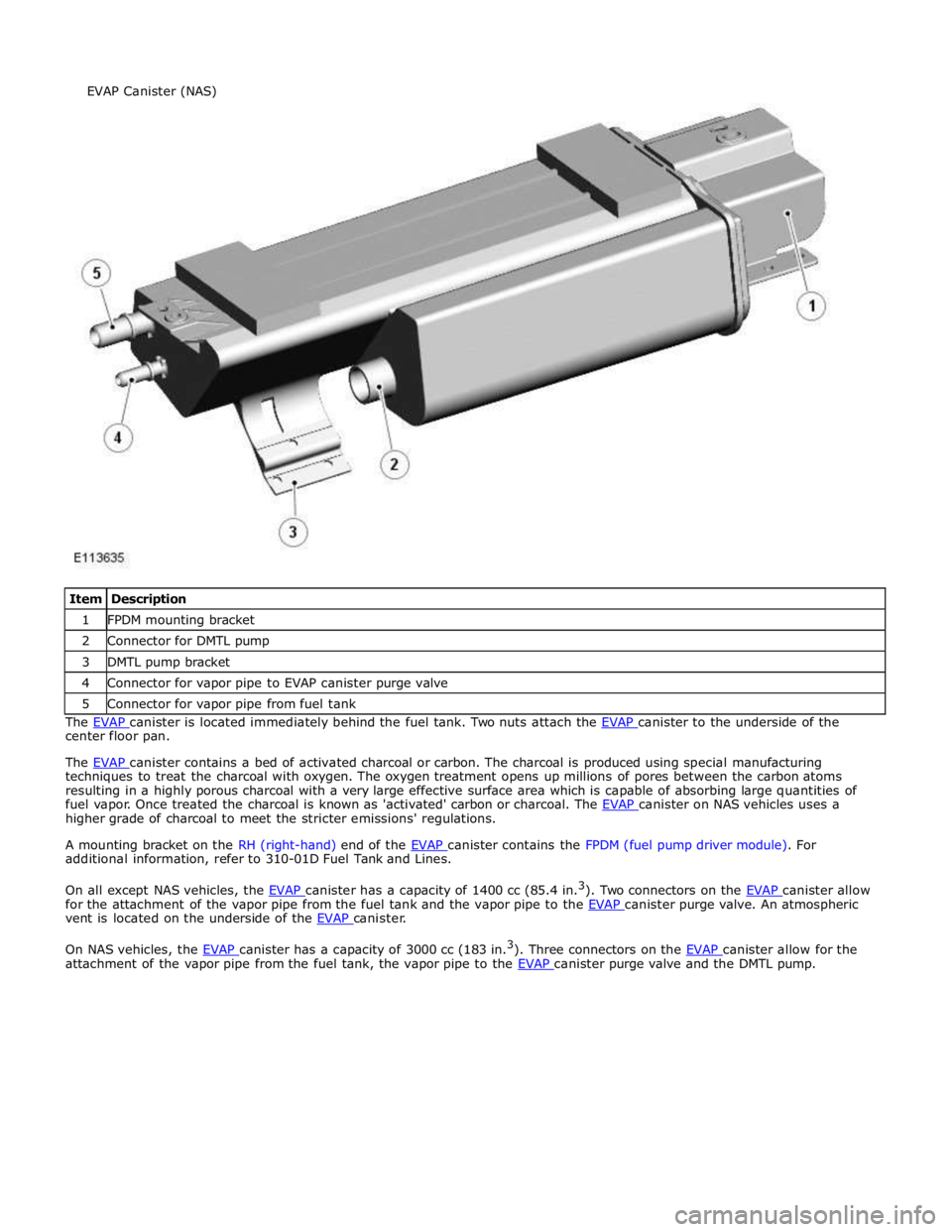
1 FPDM mounting bracket 2 Connector for DMTL pump 3 DMTL pump bracket 4 Connector for vapor pipe to EVAP canister purge valve 5 Connector for vapor pipe from fuel tank The EVAP canister is located immediately behind the fuel tank. Two nuts attach the EVAP canister to the underside of the center floor pan.
The EVAP canister contains a bed of activated charcoal or carbon. The charcoal is produced using special manufacturing techniques to treat the charcoal with oxygen. The oxygen treatment opens up millions of pores between the carbon atoms
resulting in a highly porous charcoal with a very large effective surface area which is capable of absorbing large quantities of
fuel vapor. Once treated the charcoal is known as 'activated' carbon or charcoal. The EVAP canister on NAS vehicles uses a higher grade of charcoal to meet the stricter emissions' regulations.
A mounting bracket on the RH (right-hand) end of the EVAP canister contains the FPDM (fuel pump driver module). For additional information, refer to 310-01D Fuel Tank and Lines.
On all except NAS vehicles, the EVAP canister has a capacity of 1400 cc (85.4 in.3
). Two connectors on the EVAP canister allow for the attachment of the vapor pipe from the fuel tank and the vapor pipe to the EVAP canister purge valve. An atmospheric vent is located on the underside of the EVAP canister.
On NAS vehicles, the EVAP canister has a capacity of 3000 cc (183 in.3
). Three connectors on the EVAP canister allow for the attachment of the vapor pipe from the fuel tank, the vapor pipe to the EVAP canister purge valve and the DMTL pump. EVAP Canister (NAS)
Page 1353 of 3039
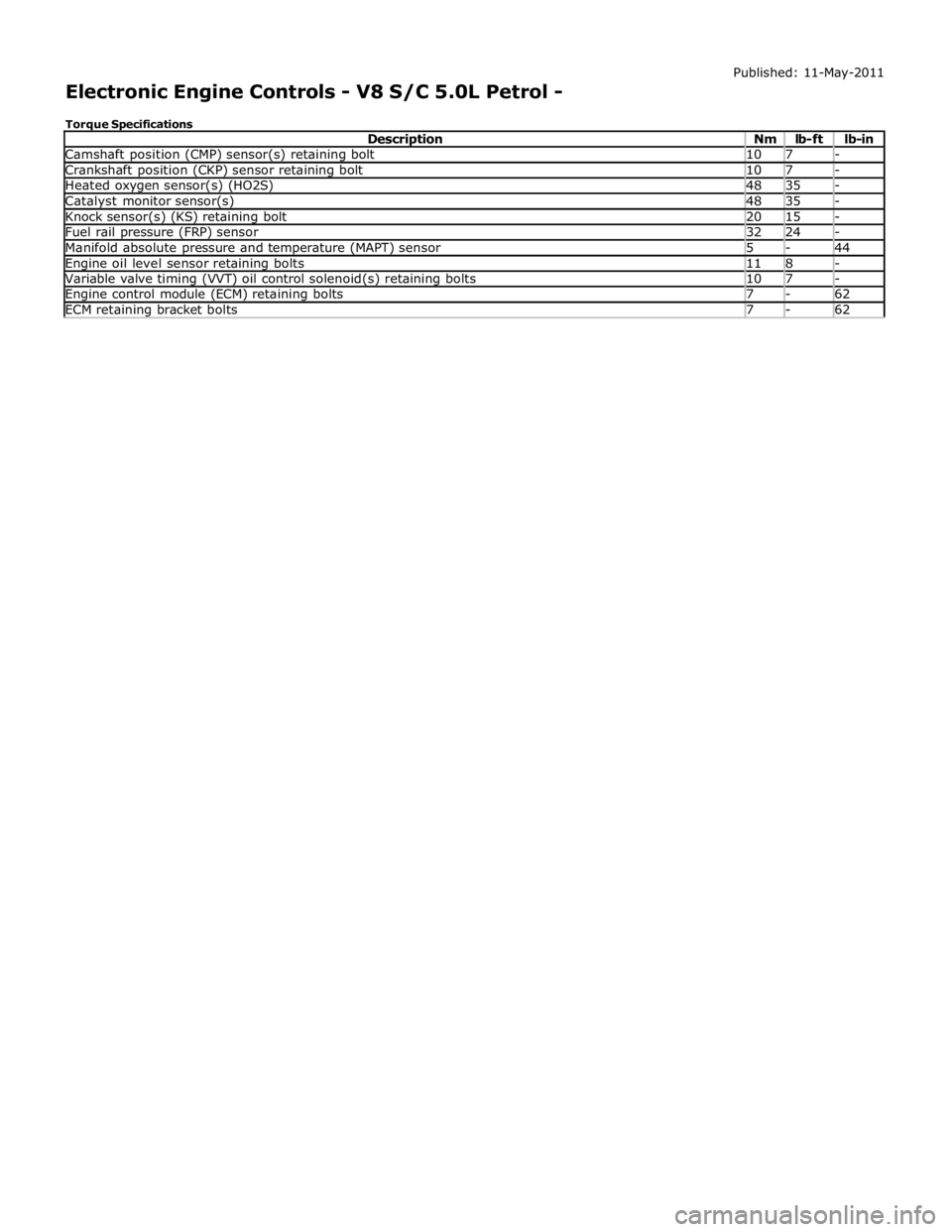
Camshaft position (CMP) sensor(s) retaining bolt 10 7 - Crankshaft position (CKP) sensor retaining bolt 10 7 - Heated oxygen sensor(s) (HO2S) 48 35 - Catalyst monitor sensor(s) 48 35 - Knock sensor(s) (KS) retaining bolt 20 15 - Fuel rail pressure (FRP) sensor 32 24 - Manifold absolute pressure and temperature (MAPT) sensor 5 - 44 Engine oil level sensor retaining bolts 11 8 - Variable valve timing (VVT) oil control solenoid(s) retaining bolts 10 7 - Engine control module (ECM) retaining bolts 7 - 62 ECM retaining bracket bolts 7 - 62
Page 1355 of 3039
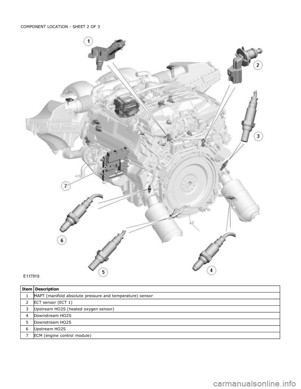
1 MAPT (manifold absolute pressure and temperature) sensor 2 ECT sensor (ECT 1) 3 Upstream HO2S (heated oxygen sensor) 4 Downstream HO2S 5 Downstream HO2S 6 Upstream HO2S 7 ECM (engine control module)
Page 1360 of 3039
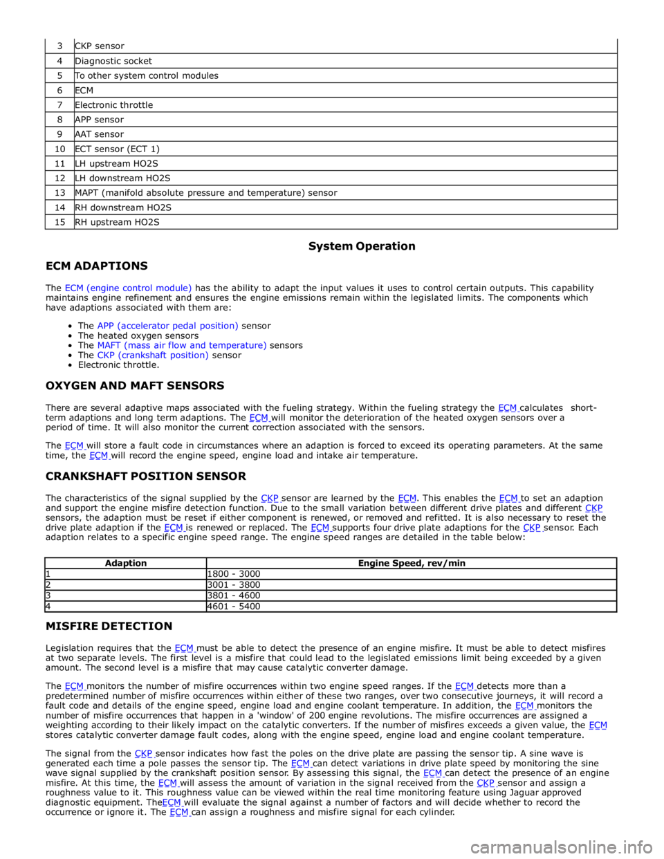
4 Diagnostic socket 5 To other system control modules 6 ECM 7 Electronic throttle 8 APP sensor 9 AAT sensor 10 ECT sensor (ECT 1) 11 LH upstream HO2S 12 LH downstream HO2S 13 MAPT (manifold absolute pressure and temperature) sensor 14 RH downstream HO2S 15 RH upstream HO2S
ECM ADAPTIONS System Operation
The ECM (engine control module) has the ability to adapt the input values it uses to control certain outputs. This capability
maintains engine refinement and ensures the engine emissions remain within the legislated limits. The components which
have adaptions associated with them are:
The APP (accelerator pedal position) sensor
The heated oxygen sensors
The MAFT (mass air flow and temperature) sensors
The CKP (crankshaft position) sensor
Electronic throttle.
OXYGEN AND MAFT SENSORS
There are several adaptive maps associated with the fueling strategy. Within the fueling strategy the ECM calculates short-term adaptions and long term adaptions. The ECM will monitor the deterioration of the heated oxygen sensors over a period of time. It will also monitor the current correction associated with the sensors.
The ECM will store a fault code in circumstances where an adaption is forced to exceed its operating parameters. At the same time, the ECM will record the engine speed, engine load and intake air temperature.
CRANKSHAFT POSITION SENSOR
The characteristics of the signal supplied by the CKP sensor are learned by the ECM. This enables the ECM to set an adaption and support the engine misfire detection function. Due to the small variation between different drive plates and different CKP sensors, the adaption must be reset if either component is renewed, or removed and refitted. It is also necessary to reset the
drive plate adaption if the ECM is renewed or replaced. The ECM supports four drive plate adaptions for the CKP sensor. Each adaption relates to a specific engine speed range. The engine speed ranges are detailed in the table below:
Adaption Engine Speed, rev/min 1 1800 - 3000 2 3001 - 3800 3 3801 - 4600 4 4601 - 5400 MISFIRE DETECTION
Legislation requires that the ECM must be able to detect the presence of an engine misfire. It must be able to detect misfires at two separate levels. The first level is a misfire that could lead to the legislated emissions limit being exceeded by a given
amount. The second level is a misfire that may cause catalytic converter damage.
The ECM monitors the number of misfire occurrences within two engine speed ranges. If the ECM detects more than a predetermined number of misfire occurrences within either of these two ranges, over two consecutive journeys, it will record a
fault code and details of the engine speed, engine load and engine coolant temperature. In addition, the ECM monitors the number of misfire occurrences that happen in a 'window' of 200 engine revolutions. The misfire occurrences are assigned a
weighting according to their likely impact on the catalytic converters. If the number of misfires exceeds a given value, the ECM stores catalytic converter damage fault codes, along with the engine speed, engine load and engine coolant temperature.
The signal from the CKP sensor indicates how fast the poles on the drive plate are passing the sensor tip. A sine wave is generated each time a pole passes the sensor tip. The ECM can detect variations in drive plate speed by monitoring the sine wave signal supplied by the crankshaft position sensor. By assessing this signal, the ECM can detect the presence of an engine misfire. At this time, the ECM will assess the amount of variation in the signal received from the CKP sensor and assign a roughness value to it. This roughness value can be viewed within the real time monitoring feature using Jaguar approved
diagnostic equipment. TheECM will evaluate the signal against a number of factors and will decide whether to record the occurrence or ignore it. The ECM can assign a roughness and misfire signal for each cylinder.
Page 1361 of 3039
DIAGNOSTICS
The ECM stores each fault as a DTC (diagnostic trouble code). The DTC and associated environmental and freeze frame data can be read using Jaguar approved diagnostic equipment, which can also read real time data from each sensor, the adaption
values currently being employed and the current fueling, ignition and idle speed settings.
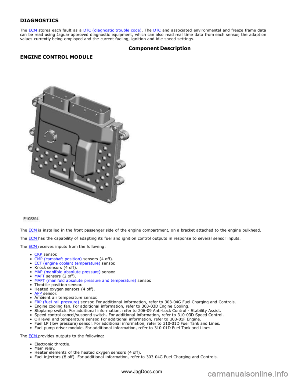
ENGINE CONTROL MODULE Component Description
The ECM is installed in the front passenger side of the engine compartment, on a bracket attached to the engine bulkhead. The ECM has the capability of adapting its fuel and ignition control outputs in response to several sensor inputs. The ECM receives inputs from the following:
CKP sensor. CMP (camshaft position) sensors (4 off).
ECT (engine coolant temperature) sensor.
Knock sensors (4 off).
MAP (manifold absolute pressure) sensor.
MAFT sensors (2 off). MAPT (manifold absolute pressure and temperature) sensor.
Throttle position sensor.
Heated oxygen sensors (4 off).
APP sensor. Ambient air temperature sensor.
FRP (fuel rail pressure) sensor. For additional information, refer to 303-04G Fuel Charging and Controls.
Engine cooling fan. For additional information, refer to 303-03D Engine Cooling.
Stoplamp switch. For additional information, refer to 206-09 Anti-Lock Control - Stability Assist.
Speed control cancel/suspend switch. For additional information, refer to 310-03D Speed Control.
Oil level and temperature sensor. For additional information, refer to 303-01F Engine.
Fuel LP (low pressure) sensor. For additional information, refer to 310-01D Fuel Tank and Lines.
Fuel pump driver module. For additional information, refer to 310-01D Fuel Tank and Lines.
The ECM provides outputs to the following: Electronic throttle.
Main relay.
Heater elements of the heated oxygen sensors (4 off).
Fuel injectors (8 off). For additional information, refer to 303-04G Fuel Charging and Controls. www.JagDocs.com
Page 1373 of 3039

DTC Description Possible Causes Action B10AC-81
Cruise Control Switch -
invalid serial data received
The Engine Control Module
(ECM) has received an invalid
command from the steering
wheel switch pack Clear the DTC and press all the steering wheel
switches, re-check for DTCs. Refer to the
electrical circuit diagrams and check the Cruise
control switch circuit for open circuit, short to
power, short to ground, disconnected. Check
and install a new Steering Wheel Module (SWM) as required. B10AC-82 Cruise Control Switch - alive / sequence counter incorrect / not updated
Cruise Buttons alive counter is
not incrementing. Which
suggests that the LIN bus is
faulty
Steering Wheel Module (SWM) is
not connected
Steering Wheel Module (SWM)
failure Refer to the electrical circuit diagrams and
check the Cruise control switch circuit for open
circuit, short to power, short to ground,
disconnected. Check and install a new Steering
Wheel Module (SWM) as required. B10AC-83
Cruise Control Switch - value
of signal protection
calculation incorrect
Cruise buttons checksum
incorrect, incorrect cruise
switches fitted to vehicle Check and install new cruise switches as
required. B10AC-96
Cruise Control Switch -
component internal failure
Cruise control switch circuit,
open circuit, short to power,
short to ground, disconnected
Cruise Control Switch failure
Steering Wheel Module (SWM)
failure Check for related DTCs in other Central
Junction Box (CJB)s. Refer to the electrical
circuit diagrams and check the Cruise control
switch circuit for open circuit, short to power,
short to ground, disconnected. Check and
install a new cruise control switch as required.
Check and install a new Steering Wheel
Module (SWM) as required. B10FF-68
Ignition Control - Event
information
Spark plug(s) fault
Wiring harness fault
Ignition coil(s) fault Refer to repair manual and check spark plug(s)
for condition and security. Replace any
defective components as required. Refer to
electrical wiring diagrams and check ignition
coil circuit for intermittent open circuit, short
to power, short to ground. Check and install a
new coil(s) as required. B11DB-01
Battery Monitoring Module -
General Electrical Failure
Charging system fault Battery
monitoring signal line
circuit fault
Vehicle battery fault Refer to electrical wiring diagrams and check
charging system for faults. Perform any repairs
required. Refer to the electrical wiring
diagrams and check the Battery Monitoring
System (BMS) module circuit for open circuit,
short to ground, short to power. Refer to the
battery care manual and check and install a
new battery. B11DB-87
Battery Monitoring Module -
missing message
Battery signal line circuit fault Refer to the electrical wiring diagrams and
check the Battery Monitoring System (BMS)
module circuit for open circuit, short to ground,
short to power. B1206-68
Crash Occurred - event
information
Engine control Module (ECM) has
detected the vehicle has crashed
- event information DTC only Refer to the electrical circuit diagrams and
check the Engine Control Module (ECM) to
Restraints Control Module (RCM) circuit for
short to ground, short to power, open circuit.
Repair circuit as required, clear DTC and retest
system to confirm repair. C0031-00
Left Front Wheel Speed
Sensor - No sub type
information
Invalid data received from
Anti-lock Braking System (ABS)
module - left front wheel speed
signal fault Check Anti-lock Braking System (ABS) module
for related DTCs and refer to relevant DTC
Index. C0034-00
Right Front Wheel Speed
Sensor - No sub type
information
Invalid data received from
Anti-lock Braking System (ABS)
module - right front wheel speed
signal fault Check Anti-lock Braking System (ABS) module
for related DTCs and refer to relevant DTC
Index. C0037-00
Left Rear Wheel Speed
Sensor - No sub type
information
Invalid data received from
Anti-lock Braking System (ABS)
module - left rear wheel speed
signal fault Check Anti-lock Braking System (ABS) module
for related DTCs and refer to relevant DTC
Index. C003A-00
Right Rear Wheel Speed
Sensor - No sub type
information
Invalid data received from
Anti-lock Braking System (ABS)
module - right rear wheel speed
signal fault Check Anti-lock Braking System (ABS) module
for related DTCs and refer to relevant DTC
Index.