key JAGUAR XFR 2010 1.G Workshop Manual
[x] Cancel search | Manufacturer: JAGUAR, Model Year: 2010, Model line: XFR, Model: JAGUAR XFR 2010 1.GPages: 3039, PDF Size: 58.49 MB
Page 2499 of 3039
NOTE: Test as a single component to ensure that the door latch is not replaced unnecessarily, when another component
may be at fault 1 Remove the door trim panel as necessary
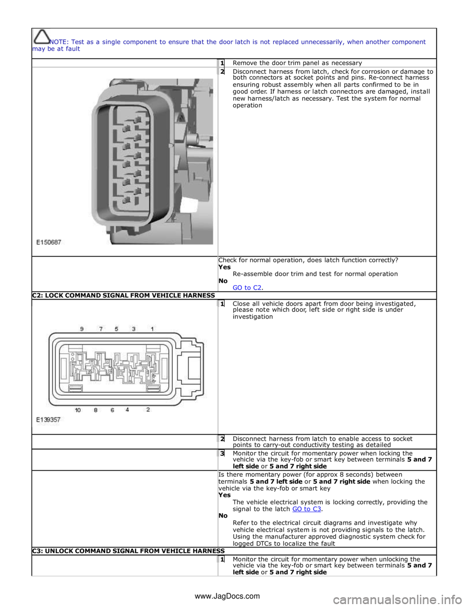
2 Disconnect harness from latch, check for corrosion or damage to both connectors at socket points and pins. Re-connect harness
ensuring robust assembly when all parts confirmed to be in
good order. If harness or latch connectors are damaged, install
new harness/latch as necessary. Test the system for normal
operation Check for normal operation, does latch function correctly? Yes
Re-assemble door trim and test for normal operation
No
GO to C2. C2: LOCK COMMAND SIGNAL FROM VEHICLE HARNESS
1 Close all vehicle doors apart from door being investigated, please note which door, left side or right side is under
investigation 2 Disconnect harness from latch to enable access to socket points to carry-out conductivity testing as detailed 3 Monitor the circuit for momentary power when locking the vehicle via the key-fob or smart key between terminals 5 and 7
left side or 5 and 7 right side Is there momentary power (for approx 8 seconds) between
terminals 5 and 7 left side or 5 and 7 right side when locking the
vehicle via the key-fob or smart key Yes
The vehicle electrical system is locking correctly, providing the
signal to the latch GO to C3. No
Refer to the electrical circuit diagrams and investigate why
vehicle electrical system is not providing signals to the latch.
Using the manufacturer approved diagnostic system check for logged DTCs to localize the fault C3: UNLOCK COMMAND SIGNAL FROM VEHICLE HARNESS 1 Monitor the circuit for momentary power when unlocking the vehicle via the key-fob or smart key between terminals 5 and 7
left side or 5 and 7 right side www.JagDocs.com
Page 2500 of 3039
Is there momentary power (for approx 8 seconds) between
terminals 5 and 7 left side and 5 and 7 right side when unlocking
the vehicle via the key-fob or smart key? Yes
The vehicle electrical system is unlocking correctly, providing
the signal to the latch GO to C4. No
Refer to the electrical circuit diagrams and investigate why
vehicle electrical system is not providing signals to the latch.
Using the manufacturer approved diagnostic system check for
logged DTCs to localize the fault C4: PHYSICAL TEST 1 1 Remove latch module from door 2 Inspect latch module for any visual damage 3 With the latch in hand, connect the electrical connector(s) to connect door latch to door harness
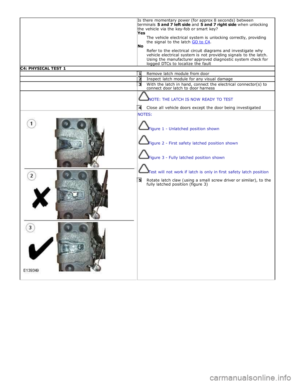
NOTE: THE LATCH IS NOW READY TO TEST 4 Close all vehicle doors except the door being investigated NOTES:
Figure 1 - Unlatched position shown
Figure 2 - First safety latched position shown
Figure 3 - Fully latched position shown
Test will not work if latch is only in first safety latch position 5 Rotate latch claw (using a small screw driver or similar), to the fully latched position (figure 3)
Page 2501 of 3039
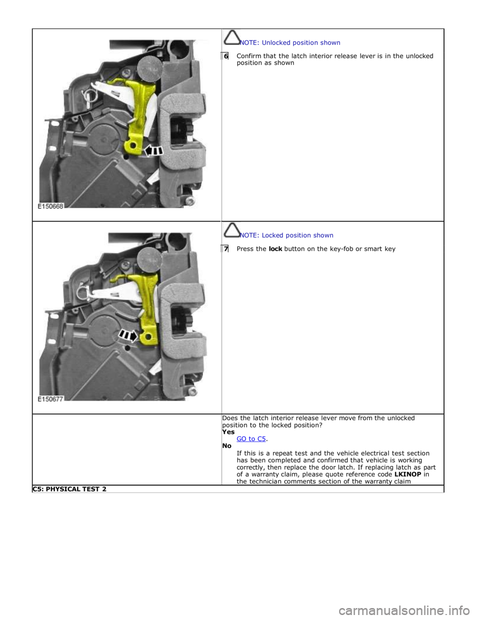
NOTE: Unlocked position shown 6 Confirm that the latch interior release lever is in the unlocked position as shown
NOTE: Locked position shown 7 Press the lock button on the key-fob or smart key Does the latch interior release lever move from the unlocked
position to the locked position? Yes
GO to C5. No
If this is a repeat test and the vehicle electrical test section
has been completed and confirmed that vehicle is working
correctly, then replace the door latch. If replacing latch as part
of a warranty claim, please quote reference code LKINOP in
the technician comments section of the warranty claim C5: PHYSICAL TEST 2
Page 2502 of 3039
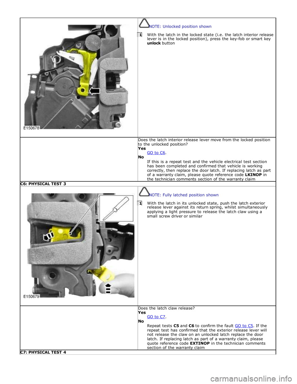
NOTE: Unlocked position shown 1 With the latch in the locked state (i.e. the latch interior release lever is in the locked position), press the key-fob or smart key
unlock button Does the latch interior release lever move from the locked position
to the unlocked position? Yes
GO to C6. No
If this is a repeat test and the vehicle electrical test section
has been completed and confirmed that vehicle is working
correctly, then replace the door latch. If replacing latch as part
of a warranty claim, please quote reference code LKINOP in
the technician comments section of the warranty claim C6: PHYSICAL TEST 3
NOTE: Fully latched position shown 1 With the latch in its unlocked state, push the latch exterior release lever against its return spring, whilst simultaneously
applying a light pressure to release the latch claw using a
small screw driver or similar Does the latch claw release? Yes
GO to C7. No
Repeat tests C5 and C6 to confirm the fault GO to C5. If the repeat test has confirmed that the exterior release lever will
not release the claw on an unlocked latch replace the door
latch. If replacing latch as part of a warranty claim, please
quote reference code EXTINOP in the technician comments
section of the warranty claim C7: PHYSICAL TEST 4
Page 2595 of 3039
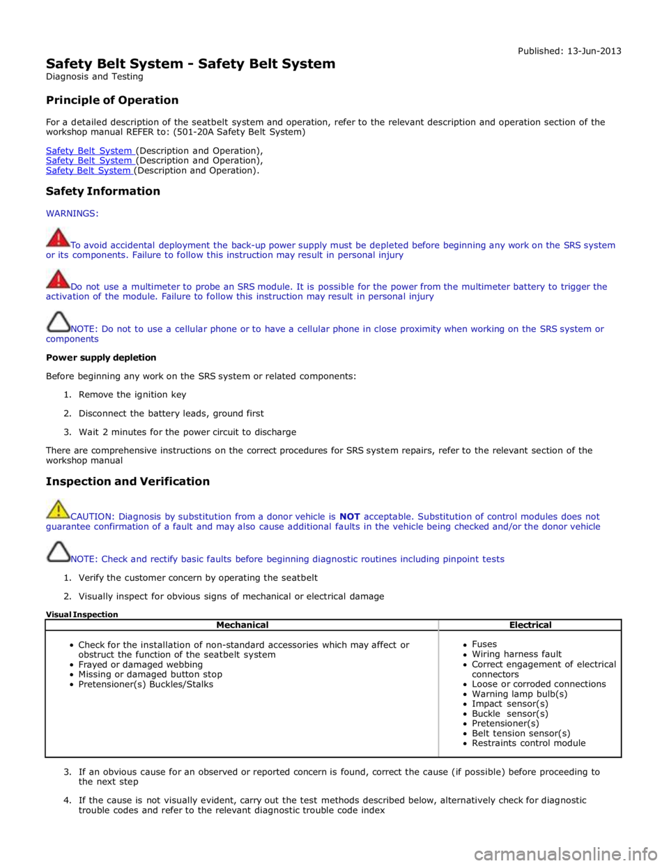
Safety Belt System - Safety Belt System
Diagnosis and Testing
Principle of Operation Published: 13-Jun-2013
For a detailed description of the seatbelt system and operation, refer to the relevant description and operation section of the
workshop manual REFER to: (501-20A Safety Belt System)
Safety Belt System (Description and Operation), Safety Belt System (Description and Operation), Safety Belt System (Description and Operation).
Safety Information
WARNINGS:
To avoid accidental deployment the back-up power supply must be depleted before beginning any work on the SRS system
or its components. Failure to follow this instruction may result in personal injury
Do not use a multimeter to probe an SRS module. It is possible for the power from the multimeter battery to trigger the
activation of the module. Failure to follow this instruction may result in personal injury
NOTE: Do not to use a cellular phone or to have a cellular phone in close proximity when working on the SRS system or
components
Power supply depletion
Before beginning any work on the SRS system or related components:
1. Remove the ignition key
2. Disconnect the battery leads, ground first
3. Wait 2 minutes for the power circuit to discharge
There are comprehensive instructions on the correct procedures for SRS system repairs, refer to the relevant section of the
workshop manual
Inspection and Verification
CAUTION: Diagnosis by substitution from a donor vehicle is NOT acceptable. Substitution of control modules does not
guarantee confirmation of a fault and may also cause additional faults in the vehicle being checked and/or the donor vehicle
NOTE: Check and rectify basic faults before beginning diagnostic routines including pinpoint tests
1. Verify the customer concern by operating the seatbelt
2. Visually inspect for obvious signs of mechanical or electrical damage
Visual Inspection
Mechanical Electrical
Check for the installation of non-standard accessories which may affect or
obstruct the function of the seatbelt system
Frayed or damaged webbing
Missing or damaged button stop
Pretensioner(s) Buckles/Stalks
Fuses
Wiring harness fault
Correct engagement of electrical
connectors
Loose or corroded connections
Warning lamp bulb(s)
Impact sensor(s)
Buckle sensor(s)
Pretensioner(s)
Belt tension sensor(s)
Restraints control module
3. If an obvious cause for an observed or reported concern is found, correct the cause (if possible) before proceeding to
the next step
4. If the cause is not visually evident, carry out the test methods described below, alternatively check for diagnostic
trouble codes and refer to the relevant diagnostic trouble code index
Page 2616 of 3039
and the safety belt buckle sensor. Based on this data, the RCM decides which level of airbag module deployment is required and forwards the information to the second area, the deployment handler.
The deployment handler evaluates the status of the seat track position sensor and safety belt buckle sensors before a decision
is made about which restraints should finally be deployed.
Data from the side crash sensors is used by the RCM in conjunction with acceleration data from the RCM internal accelerometer to make a deployment decision. The RCM processes the acceleration data and subject to an impact being of high enough severity, decides whether the side airbag module should be deployed.
On board testing of the airbag modules, front safety belt pretensioner firing circuits, warning indicator circuits and module
status (the crash and side impact sensors perform basic self-tests) is performed by the RCM together with the storing of fault codes.
The RCM drives the SRS indicator on the instrument pack via a CAN signal. If the warning lamp fails, a fault code is recorded and a warning tone is sounded in place of the lamp if a further fault occurs. It also provides a temporary back-up power supply
to operate the airbag modules in the event that in crash conditions, the battery supply is lost. In the event of a crash, it
records certain data which can be accessed via the diagnostic connector.
A safing sensor in the RCM provides confirmation of an impact to verify if airbag and pretensioner activation is necessary. A roll-over sensor monitors the lateral attitude of the vehicle. Various firing strategies are employed by the RCM to ensure that during an accident only the appropriate airbags and pretensioners are fired. The firing strategy used also depends on the
inputs from the safety belt switches and the occupant monitoring system.
An energy reserve in the RCM ensures there is always a minimum of 150 milliseconds of stored energy available if the power supply from the ignition switch is disrupted during a crash. The stored energy is sufficient to produce firing signals for the
driver airbag, the passenger airbag and the safety belt pretensioners.
When the ignition is switched on, the RCM performs a self-test and then performs cyclical monitoring of the system. If a fault is detected the RCM stores a related fault code and illuminates the airbag warning indicator. The faults can be retrieved by the recommended Jaguar diagnostic tool over the CAN bus. If a fault that could cause a false fire signal is detected, the RCM disables the respective firing circuit, and keeps it disabled during a crash event.
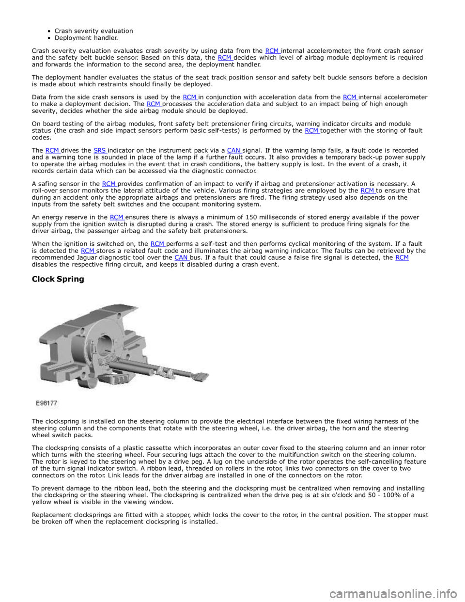
Clock Spring
The clockspring is installed on the steering column to provide the electrical interface between the fixed wiring harness of the
steering column and the components that rotate with the steering wheel, i.e. the driver airbag, the horn and the steering
wheel switch packs.
The clockspring consists of a plastic cassette which incorporates an outer cover fixed to the steering column and an inner rotor
which turns with the steering wheel. Four securing lugs attach the cover to the multifunction switch on the steering column.
The rotor is keyed to the steering wheel by a drive peg. A lug on the underside of the rotor operates the self-cancelling feature
of the turn signal indicator switch. A ribbon lead, threaded on rollers in the rotor, links two connectors on the cover to two
connectors on the rotor. Link leads for the driver airbag are installed in one of the connectors on the rotor.
To prevent damage to the ribbon lead, both the steering and the clockspring must be centralized when removing and installing
the clockspring or the steering wheel. The clockspring is centralized when the drive peg is at six o'clock and 50 - 100% of a
yellow wheel is visible in the viewing window.
Replacement clocksprings are fitted with a stopper, which locks the cover to the rotor, in the central position. The stopper must
be broken off when the replacement clockspring is installed.
Page 2617 of 3039
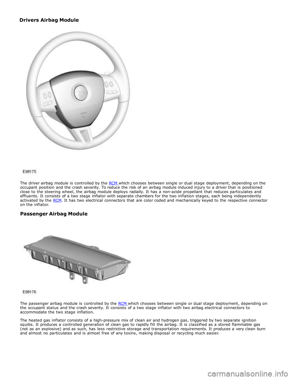
occupant position and the crash severity. To reduce the risk of an airbag module induced injury to a driver that is positioned
close to the steering wheel, the airbag module deploys radially. It has a non-azide propellant that reduces particulates and
effluents. It consists of a two stage inflator with separate chambers for the two inflation stages, each being independently
activated by the RCM. It has two electrical connectors that are color coded and mechanically keyed to the respective connector on the inflator.
Passenger Airbag Module
The passenger airbag module is controlled by the RCM which chooses between single or dual stage deployment, depending on the occupant status and the crash severity. It consists of a two stage inflator with two airbag electrical connectors to
accommodate the two stage inflation.
The heated gas inflator consists of a high-pressure mix of clean air and hydrogen gas, triggered by two separate ignition
squibs. It produces a controlled generation of clean gas to rapidly fill the airbag. It is classified as a stored flammable gas
(not as an explosive) and as such, has less restrictive storage and transportation requirements. It produces a very clean burn
and almost no particulates and is almost free of any toxins, making disposal or recycling much easier. Drivers Airbag Module
Page 2622 of 3039
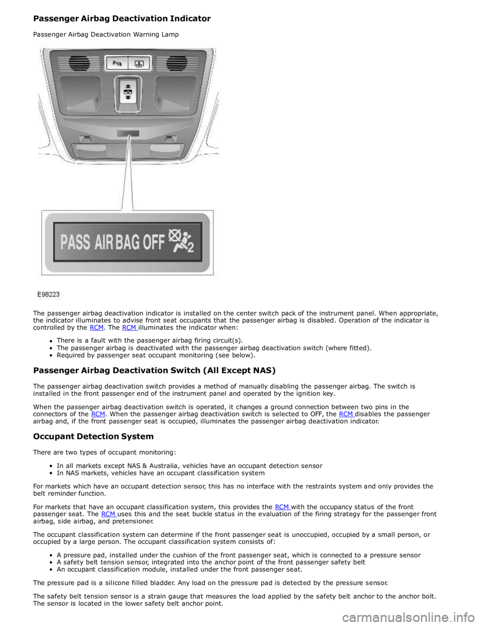
There is a fault with the passenger airbag firing circuit(s).
The passenger airbag is deactivated with the passenger airbag deactivation switch (where fitted).
Required by passenger seat occupant monitoring (see below).
Passenger Airbag Deactivation Switch (All Except NAS)
The passenger airbag deactivation switch provides a method of manually disabling the passenger airbag. The switch is
installed in the front passenger end of the instrument panel and operated by the ignition key.
When the passenger airbag deactivation switch is operated, it changes a ground connection between two pins in the
connectors of the RCM. When the passenger airbag deactivation switch is selected to OFF, the RCM disables the passenger airbag and, if the front passenger seat is occupied, illuminates the passenger airbag deactivation indicator.
Occupant Detection System
There are two types of occupant monitoring:
In all markets except NAS & Australia, vehicles have an occupant detection sensor
In NAS markets, vehicles have an occupant classification system
For markets which have an occupant detection sensor, this has no interface with the restraints system and only provides the
belt reminder function.
For markets that have an occupant classification system, this provides the RCM with the occupancy status of the front passenger seat. The RCM uses this and the seat buckle status in the evaluation of the firing strategy for the passenger front airbag, side airbag, and pretensioner.
The occupant classification system can determine if the front passenger seat is unoccupied, occupied by a small person, or
occupied by a large person. The occupant classification system consists of:
A pressure pad, installed under the cushion of the front passenger seat, which is connected to a pressure sensor
A safety belt tension sensor, integrated into the anchor point of the front passenger safety belt
An occupant classification module, installed under the front passenger seat.
The pressure pad is a silicone filled bladder. Any load on the pressure pad is detected by the pressure sensor.
The safety belt tension sensor is a strain gauge that measures the load applied by the safety belt anchor to the anchor bolt.
The sensor is located in the lower safety belt anchor point.
Page 2638 of 3039
Published: 11-May-2011
Supplemental Restraint System - Occupant Classification Sensor
Removal and Installation
Removal
WARNINGS:
To avoid accidental deployment, the restraints control module backup power supply must be depleted. Wait at least one
minute after disconnecting the battery ground cable(s) before commencing any repair or adjustment to the supplemental
restraint system (SRS), or any component(s) adjacent to the SRS sensors. Failure to follow these instructions may result in
personal injury.
Always wear safety glasses when working on an air bag equipped vehicle and when handling an air bag module. Failure to
follow this instruction may result in personal injury.
To minimize the possibility of premature deployment, do not use radio key code savers when working on the
supplemental restraint system. Failure to follow this instruction may result in personal injury.
To minimize the possibility of injury in the event of premature deployment, always carry a live air bag module with the
bag and trim cover pointed away from the body. Failure to follow this instruction may result in personal injury.
To minimize the possibility of premature deployment, live air bag modules must only be placed on work benches which
have been ground bonded and with the trim cover facing up. Failure to follow these instructions may result in personal injury.
Never probe the electrical connectors of air bag modules or any other supplemental restraint system component. Failure
to follow this instruction may result in personal injury.
Painting over the driver air bag module trim cover or instrument panel could lead to deterioration of the trim cover and air
bags. Do not for any reason attempt to paint discoloured or damaged air bag module trim covers or instrument panel. Install a
new component. Failure to follow this instruction may result in personal injury.
CAUTIONS:
The front passenger seat occupant classification sensor is available only as a service kit. No attempt should be made to
replace individual components. Failure to follow this instruction may result in personal injury.
Check for correct operation of the front seat after completion of the procedure to make sure that the wiring harness has
not become trapped or stretched.
NOTES:
Note the routing of the seat harness.
Some variation in the illustrations may occur, but the essential information is always correct.
1. Make the air bag supplemental restraint system (SRS) safe.
Refer to: Standard Workshop Practices (100-00 General Information, Description and Operation).
2. Refer to: Battery Disconnect and Connect (414-01 Battery, Mounting and Cables, General Procedures).
3. Refer to: Front Seat Backrest Cover (501-10 Seating, Removal and Installation).
Page 2694 of 3039

Part N-umber
Body Repairs - General Information - Body Repairs
Description and Operation
General Information
Introduction Published: 11-May-2011
The body plays a significant role in the increasing trend of ever more rapidly changing model variants. The different customer
groups are strongly influenced by the design and shape of the body. At the same time the stability of the body plays the most
important part in ensuring passenger and driver safety. Lightweight construction, alternative materials, composite materials,
plastics and appropriate joining processes are all design features that characterise modern Jaguar vehicle bodies.
In terms of manufacturing technology, modern safety cell bodies can be produced almost without any problems. Jaguar
guarantee high quality standards by ensuring that mechanical strength properties are tried and tested in numerous computer
simulations, crash tests, by testing materials and by employing sophisticated manufacturing technologies. In the event of
repairs it is vital that the production quality standards are upheld. This requires a well-equipped workshop, and places
particular emphasis on the qualifications of the workshop technicians. Up-to-date knowledge of current manufacturing
technologies and continuous training on new repair methods and techniques are vital for high-quality body repairs. The model-
specific repair manuals and the general repair techniques provide valuable support when undertaking body repairs.
Always follow the repair instructions published in this manual. Failure to observe this instruction can result in serious
impairment of vehicle safety. All specified safety requirements must be met after the work has been carried out.
Vehicle design
The body
The XF adopts the latest generation steels, especially in the upper body – including high carbon steels, dual-phase,
hot-formed boron steels, and bake-hardened steels to form a vertical safety ‘ring’ around the occupant cell. As well as
combining strength with lightness, these steels improve corrosion resistance, by making best use of zinc and improving e-coat
paint flow – and new thinking means that in spite of their strength, the XF’s A and B-pillars are impressively slim, to the
benefit of both visibility and accessibility. Similarly, the lower sills are the first component on any Jaguar to use incredibly
strong, dual-phase DP600 steel.
The safety of the driver and the passengers is paramount for every body design. There are two key safety aspects in the body:
Safety passenger cell
Crumple zones
Safety passenger cell
Stable pillars, rocker panel and door profiles.
Side impact protection in the doors.
Doors are designed to open even in the event of extreme deformation.
Crumple zone
Dynamic absorption of deforming forces.
Protection of the passenger cell. www.JagDocs.com