key JAGUAR XFR 2010 1.G Manual PDF
[x] Cancel search | Manufacturer: JAGUAR, Model Year: 2010, Model line: XFR, Model: JAGUAR XFR 2010 1.GPages: 3039, PDF Size: 58.49 MB
Page 2039 of 3039

Exterior Lighting - Headlamp Adjustment
General Procedures Published: 16-Apr-2014
NOTE: Some variation in the illustrations may occur, but the essential information is always correct.
1. Make sure to check and adjust the tyre pressures to the correct
level.
Park the vehicle on a horizontally level surface.
2. Align the headlamp beam setting equipment to one headlamp.
Headlamp beam setter
3. NOTE: The headlamp setting is 1 % below horizontal and parallel.
Check the headlamp beam alignment.
4. Open the hood.
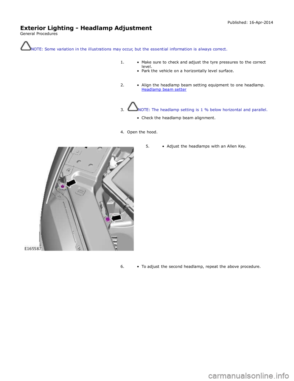
5. Adjust the headlamps with an Allen Key.
6. To adjust the second headlamp, repeat the above procedure.
Page 2058 of 3039

3 BJB - Megafuse 4 RJB 5 Glovebox lamp 6 Glovebox lamp switch 7 LH footwell lamp 8 RH footwell lamp 9 LH vanity mirror 10 RH vanity mirror 11 LH rear interior lamp 12 RH rear interior lamp 13 CJB 14 Ambience lighting LED's 15 LH map reading lamp 16 Courtesy lamp 17 RH map reading lamp
JUNCTION BOXES
Inputs System Operation
The CJB receives the following inputs which affect the operation of the interior lamps: Ignition mode
Lock/unlock
Luggage compartment lid latch switch
Door latch switches.
Outputs
The RJB outputs the following for the interior lighting system: Luggage compartment lamp power supply
Driver and passenger door module power supplies
Fade on and off grounds for front and rear overhead console interior lamps and footwell lamps
PWM (pulse width modulation) power output for the ambience lighting.
Interior Lamp Time-Out
The interior lamps are controlled by a timer within the CJB which allows a 60 second delay period for the lamps to remain active after the ignition mode has been changed to off power mode 0 or the vehicle has been unlocked. The interior lamp fade
off is controlled by the RJBvia a delayed power off relay in the CJB. The following interior lamps are subject to the delay period:
Front overhead console interior lamp
Rear interior lamps
Footwell lamps
Door mirror approach lamps.
The timer delay is activated when the CJB receives one of the following signals: An unlock signal from the Smart Key via the keyless vehicle module.
Ignition mode is changed from the crank power mode 9 or ignition power mode 6 to the accessory power mode 4 to the
off power mode 0.
If a second occurrence of the above actions occurs within the timer period, the timer will be rest and the delay period timer will
restart.
The timer delay is deactivated when the CJB receives one of the following signals: A lock signal from the Smart Key via the keyless vehicle module
Ignition mode is changed from the off power mode 0 to the accessory power mode 4 or ignition power mode 6
The CJB receives a door opened signal (even if that door is subsequently closed). Battery Saver
The battery saver provides an automatic shut-off of the interior lamps after a period of 15 minutes in order to prevent
excessive power drain on the battery.
When the ignition mode is changed from the ignition power mode 6 or accessory power mode 4 to the off power mode 0, the
CJB starts a timer which de-energizes a delayed power off relay in the CJB, removing the power supply to the interior lamps after a period of 15 minutes, switching off all or any interior lamps which have remained on for any reason.
Page 2059 of 3039

Once the timer has expired and the lamps are off, any one of the following will 'wake up' the battery saver and the interior
lamps will function again. The timer will be restarted as soon as an input is received by the CJB from one of the following:
Ignition mode changed from off power mode 0 to accessory power mode 4, ignition power mode 6 or crank power mode
9.
Any door, including the luggage compartment lid is opened
An unlock request is received from the Smart Key via the keyless vehicle module
Overhead console interior lamp is switched on via the JaguarSense function.
INTERIOR LAMPS
When the interior lighting system switches the interior lamps on, the CJB ramps the lamps up to full power over a period of 1.3 seconds. When the system switches the lamps off, after the time-out period has expired, the CJB fades the lamps off over a period of 2.6 seconds.
The interior lighting system will illuminate the interior lamps when one of the following events occurs:
The CJB receives an unlock signal from the Smart Key via the keyless vehicle module Any door is opened including the luggage compartment lid
The ignition mode is changed from ignition power mode 6 or accessory power mode 4 to off power mode 0.
The interior lighting system will turn off the interior lamps when one of the following events occurs:
Once the time-out timer delay has expired since the lamps were either activated or the last door is closed and the
vehicle is not locked
The ignition is in off power mode 0 and an external lock is requested (using either the door lock buttons or the Smart
Key) with all doors closed
The ignition mode is changed from the off power mode 0 or the accessory power mode 4 to the ignition power mode 6
The last door is closed and the vehicle is externally locked, on receipt of an unlock request from the Smart Key or door
handle operation detected when the time-out timer is still active.
DELIVERY MODE
Delivery mode is set at the factory on vehicles to minimize battery drain. The mode enables the switching off of non-critical
electrical components, including the interior lighting system. The delivery mode feature is cancelled by the dealer during the
Pre-Delivery Inspection using an approved Jaguar diagnostic system.
CRASH ILLUMINATION
When a crash signal is received from the RCM (restraints control module), the CJB activates the interior lamps once the vehicle speed has reduced to 5 km/h (3.1 mph). The hazard flashers are also activated and the doors are prevented from being locked.
The lamps remain on until the crash signal is removed, they cannot be switched off using the JaguarSense feature. The crash
signal is removed by completing one ignition on and off cycle.
INTERIOR BULB TYPE/RATING Component Description
The following table shows the bulbs used for the interior lighting system and their type and specification.
NOTE: The front overhead console and the front door ambience lighting is illuminated by LED's and are non-serviceable components.
Bulb Type Rating Front overhead console - interior lamp W6WX 6W Front overhead console - LH/RH map reading lamps W6WX 6W Rear interior lamps W6WX 10W Sunvisor lamps TS1.3W 1.3W LH/RH footwell lamps W5W 5W Glovebox lamp W5W 5W LH/RH door mirror approach lamps W5W 5W Luggage compartment lamp S10W 10W JUNCTION BOXES
The CJB is an integrated unit located on the RH 'A' pillar, below the instrument panel. The CJB contains fuses, relays and number of microprocessors which control the power supply and functionality of the interior lighting system and other vehicle
systems.
The RJB is located on the RH side of the luggage compartment. The RJB contains fuses, relays and microprocessors which in conjunction with the CJB control the interior lighting system and other vehicle systems. Circuit Protection
The CJB and the RJB provide circuit protection for all interior lamp circuits. The lamps are protected by fuses in the CJB and the RJB.
Page 2071 of 3039

N = Medium speed CAN (controller area network) bus 1 Parking aid module 2 RJB 3 Keyless vehicle module 4 RH blind spot monitoring module 5 Driver's seat module 6 Front seat climate control module 7 Information control module 8 ATC module 9 CJB 10 Diagnostic socket 11 Instrument cluster 12 Integrated control panel 13 Front passenger door control module
Page 2085 of 3039

DTC Description Possible Cause Action B100951
Ignition
Authorisation
Faulty instrument cluster
Target SID re-synchronisation
error following programming
CAN fault Check ignition, power and ground supplies to CJB and
instrument cluster. Re-synchronize ID by re-configuring
the instrument cluster as a new module. Check CAN
communications between instrument cluster and tester B100962
Ignition
Authorisation
Low speed CAN fault
CJB fault
Instrument cluster fault
Incorrect module installed
(CJB/Instrument cluster)
Target SID synchronisation
error following re-programming
Noise/EMC related error Check CAN communications between CJB and instrument
cluster. Check ignition, power and ground supplies to CJB
and instrument cluster. Confirm correct module is
installed. Re-synchronise ID by re-configuring the
instrument cluster as a new module. Check CAN network
for interference/EMC related issues B100963
Ignition
Authorisation
CJB fault
Low speed CAN fault
Instrument cluster fault
Low battery voltage <9V Check Power and Ground supplies to CJB and instrument
cluster. Check CAN communications between CJB and
instrument cluster. Check battery is in fully charged and
serviceable condition, refer to the battery care manual B100964
Ignition
Authorisation
CJB fault
Low speed CAN fault
Instrument cluster fault Check power and ground supplies to CJB and instrument
cluster. Check CAN communications between CJB and
instrument cluster B102B67 Passive Key
CJB fault
Low speed CAN fault
Remote Keyless Entry (RKE)
module fault
Write target SID
synchronisation error following
re-programming Check power and ground supplies to CJB and RKE
module. Check CAN communications between CJB and
RKE module. Re-synchronise ID by re-configuring the RKE
module as a new module B102B87 Passive Key
CJB fault
Low speed CAN fault
RKE module fault
Key fob battery low/battery
contact issue
Interference from other RF
signal
EMC/noise
Receiver fault
Receiver not programmed
correctly
Serial communications fault
(between receiver and RKE
module)
Key fault
Passive antenna fault
Confirm placement of key
within vehicle Check power and ground supplies to CJB, RKE module
and receiver. Check CAN communications between CJB
and instrument cluster. Check key fob battery. Confirm
vehicle surroundings, move vehicle. Check CAN network
for interference/EMC related issues. Disconnect battery,
then re-connect - confirm operation by re-programming
keys. Check serial circuit between receiver and RKE
module. Confirm spare key works. Refer to the electrical
circuit diagrams and test circuits to all 3 antennas. Check
whereabouts of key B108413
Boot/Trunk Motor
Close Switch
Trunk latch open signal circuit -
open circuit Refer to the electrical circuit diagrams and check trunk
latch open signal circuit for open circuit B108783 LIN Bus "A"
Checksum of the received LIN
frame from battery backed
sounder, roof header console,
and/or rain/light sensor is
incorrect Check operation of rain/light sensor by covering sensor or
applying water to screen, install a new sensor as
required B108788 LIN Bus "A"
Bus off. Battery backed
sounder, roof header console,
and/or rain/light sensor LIN
circuit - short to ground, power Carry out any pinpoint tests associated with this DTC
using the manufacturer approved diagnostic system.
Refer to the electrical circuit diagrams and check battery
backed sounder, roof header console, and rain/light
sensor LIN circuit for short to ground, power B108A11 Start Button
Start/Stop switch analogue
input circuits 1 or 2 - short to
ground Refer to the electrical circuit diagrams and check
Start/Stop switch analogue input circuits 1 and 2 for
short to ground www.JagDocs.com
Page 2086 of 3039

DTC Description Possible Cause Action B108A12 Start Button
Start/Stop switch analogue
input circuits 1 or 2 - short to
power Refer to the electrical circuit diagrams and check
Start/Stop switch analogue input circuits 1 and 2 for
short to power B109512 Wiper On/Off Relay
Wiper On/Off relay control
circuit - short to power Carry out any pinpoint tests associated with this DTC
using the manufacturer approved diagnostic system.
Refer to the electrical circuit diagrams and check wiper
On/Off relay control circuit for short to power B109514 Wiper On/Off Relay
Wiper On/Off relay control
circuit - short to ground, open
circuit Refer to the electrical circuit diagrams and check wiper
On/Off relay control circuit for short to ground, open
circuit B109612
Wiper High/Low
Relay
Wiper Fast/Slow relay control
circuit - short to power Carry out any pinpoint tests associated with this DTC
using the manufacturer approved diagnostic system.
Refer to the electrical circuit diagrams and check wiper
Fast/Slow relay control circuit for short to power B109614
Wiper High/Low
Relay
Wiper Fast/Slow relay control
circuit - short to ground, open
circuit Refer to the electrical circuit diagrams and check wiper
Fast/Slow relay control circuit for short to ground, open
circuit B109712
Heated Windshield
Relay
Heated windshield relay control
circuit - short to power Carry out any pinpoint tests associated with this DTC
using the manufacturer approved diagnostic system.
Refer to the electrical circuit diagrams and check heated
windshield relay control circuit for short to power B109714
Heated Windshield
Relay
Heated windshield relay control
circuit - short to ground, open
circuit Refer to the electrical circuit diagrams and check heated
windshield relay control circuit for short to ground, open
circuit B10A612 Main Light Switch
Master light switch signal from
roof header console circuit -
short to power Refer to the electrical circuit diagrams and check master
light switch signal from roof header console circuit for
short to power B10A623 Main Light Switch
Master light switch signal from
roof header console signal
stuck low. Switch is read as ON
for too long a time Carry out any pinpoint tests associated with this DTC
using the manufacturer approved diagnostic system.
Refer to the electrical circuit diagrams and check master
light switch signal from roof header console for short to
ground B10AD09 Rain Sensor
Component failures Carry out any pinpoint tests associated with this DTC
using the manufacturer approved diagnostic system.
Suspect the rain/light sensor, check and install a new
sensor as required B10AD11 Rain Sensor
Rain/light sensor power circuit -
short to ground Carry out any pinpoint tests associated with this DTC
using the manufacturer approved diagnostic system.
Refer to the electrical circuit diagrams and check rain/light sensor power circuit for short to ground B10AD96 Rain Sensor
Component internal failure Suspect the rain/light sensor, check and install a new
sensor as required B10E511
PCM Wake-up
Signal
ECM wake-up signal circuit -
short to ground Refer to the electrical circuit diagrams and check ECM
wake-up signal circuit for short to ground B10E512
PCM Wake-up
Signal
ECM wake-up signal circuit -
short to power Refer to the electrical circuit diagrams and check ECM
wake-up signal circuit for short to power B10E513
PCM Wake-up
Signal
ECM wake-up signal circuit -
open circuit Refer to the electrical circuit diagrams and check ECM
wake-up signal circuit for open circuit B10F111 Key In Switch
Keyless vehicle module, key IN
status circuit - short to ground Carry out any pinpoint tests associated with this DTC
using the manufacturer approved diagnostic system.
Refer to the electrical circuit diagrams and check keyless
vehicle module, key IN status circuit for short to ground B10F112 Key In Switch
Keyless vehicle module, key IN
status circuit - short to power Refer to the electrical circuit diagrams and check keyless
vehicle module, key IN status circuit for short to power B10F113 Key In Switch
Keyless vehicle module, key IN
status circuit - open circuit Refer to the electrical circuit diagrams and check keyless
vehicle module, key IN status circuit for open circuit
Page 2119 of 3039

Anti-Theft - Active - Anti-Theft - Active - Component Location
Description and Operation
Component Location Published: 11-May-2011
Item Description 1 Alarm indicator 2 Latch mechanism - front door 3 Intrusion detection module 4 Latch mechanism - rear door 5 Central locking Radio Frequency (RF) receiver 6 Luggage compartment lid latch mechanism 7 Keyless vehicle module 8 Latch mechanism - rear door 9 Latch mechanism - front door
Page 2122 of 3039

Published: 11-May-2011
Anti-Theft - Active - Anti-Theft - Active - System Operation and Component Description
Description and Operation
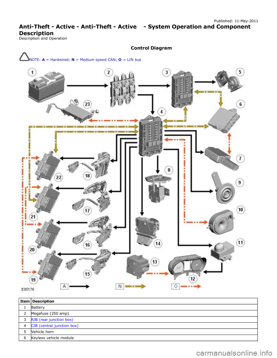
Control Diagram
NOTE: A = Hardwired; N = Medium speed CAN; O = LIN bus
Item Description 1 Battery 2 Megafuse (250 amp) 3 RJB (rear junction box) 4 CJB (central junction box) 5 Vehicle horn 6 Keyless vehicle module
Page 2123 of 3039

7 Central locking - Radio Frequency (RF) receiver 8 Engine compartment lid - latch mechanism 9 Passive sounder 10 Battery backed sounder 11 Alarm indicator 12 Instrument cluster 13 Start control unit 14 Luggage compartment lid - latch mechanism 15 Door latch mechanism - LH (left-hand) rear 16 Door latch mechanism - RH (right-hand) rear 17 Door latch mechanism - RH front 18 Door latch mechanism - LH front 19 Door module - LH rear 20 Door module - RH rear 21 Door module - RH front 22 Door module - LH front 23 Intrusion detection module
Anti-Theft - Active System Operation
The active anti-theft system is available with three different levels of vehicle protection depending on market specification:
Hinged panel sensing
Hinged panel and intrusion sensing
Hinged panel, intrusion and inclination sensing.
The system is controlled by software in the CJB and RJB and indicates a trigger condition: Visually, using the direction indicators, and
Audibly, using the vehicle horn and either a passive or active sounder to indicate a trigger condition.
The passive sounder takes the form of an anti-theft disc horn located at the rear of the engine compartment on the LH side. The active sounder takes the form of a battery backed sounder located in the same position.
Depending on market specification, the battery backed sounder may be fitted with an inclination sensor. Both types of battery
backed sounder are visually identical and can only be identified by their part number. Both are also intelligent units, and
communicate to the CJB over a LIN (local interconnect network) bus connection.
Monitoring of the hinged panels is carried out using switches located in each door latch assembly, the engine-compartment-lid
latch assembly, and the luggage-compartment-lid latch assembly. The condition of the switches is monitored by the CJB.
Monitoring of front door lock status is carried out using switches located in the door latch mechanisms. The condition of the
switches is monitored by the front door modules and transmitted to the CJB over the medium speed CAN (controller area
network) bus.
Monitoring of the cabin interior is carried out using an intrusion detection module mounted behind the roof console. The
intrusion detection module comprises an ultrasonic sound wave sensor to determine if there is movement within the cabin.
Information from the intrusion detection module is communicated to the CJB over a LIN bus connection.
CAUTIONS:
The intrusion detection module electrical connections, particularly those to the sensors mounted in the roof console, are
very delicate and must be handled with care.
The intrusion detection module is an electro-statically sensitive part and should only be handled in an electro-statically
controlled environment.
When armed, the active anti-theft system can be triggered in one of the following ways:
A door ajar switch indicates a door has been opened.
The engine compartment lid or luggage compartment lid ajar switches indicate that either has been opened.
Either front door latch mechanism indicates a door has been unlocked.
The emergency key blade is used to open either the LH front door or luggage compartment.
The CJB or RJB are disconnected (this may result in only a partial trigger).
An attempt is made to start the engine without a valid signal from the Smart Key.
Refer to: Anti-Theft - Passive (419-01B Anti-Theft - Passive, Description and Operation).
Page 2124 of 3039

The battery backed sounder is disconnected (partial trigger only).
The vehicle battery is disconnected on a vehicle fitted with a battery backed sounder (partial trigger only).
The inclination sensor detects a change in vehicle attitude.
The intrusion detection module detects movement within the cabin.
Door Modules Component Description
The door modules provide the interface between the door latch-motors, the door latch-switches and the CJB. The door modules
provide door switch status information and enable the door latch-motors on request from the CJB or the keyless vehicle
module.
Keyless Vehicle Module
The keyless vehicle module interfaces with the Central locking, Radio Frequency (RF) receiver and collects RF signal information
which is transmitted from the Smart Key. This information is translated into commands which are passed on the medium speed
CAN bus to the:
CJB,
RJB,
door modules, and
instrument cluster.
The keyless vehicle module also monitors:
2 interior antennae,
1 luggage compartment antenna,
a rear bumper antenna, and
4 door handle antennae if the passive entry system is fitted.
On vehicles with passive entry, the additional fast latch motors are controlled via the keyless vehicle module and the locking
status is passed to the CJB on the medium speed CAN bus.
Instrument Cluster
The instrument cluster controls the alarm indicator, and in conjunction with the ECM (engine control module), the engine
immobilization. The ECM controls the engine crank and fuel functions and the instrument cluster processes the valid
transponder information.
Alarm Indicator
The alarm indicator is a LED (light emitting diode) located in the body of the sunload/light sensor. When the ignition is off the
indicator gives a visual indication of the active anti-theft system to show if the alarm system is active or not active. Operation
of the alarm indicator is controlled by the instrument cluster which varies the flash rate of the LED to indicate the system
status of the alarm and the immobilization systems.
When the ignition is on, the indicator provides a visual indication of the status of the passive anti-theft (engine
immobilization) system. If the immobilization system is operating correctly, the LED will be illuminated for 3 seconds at
ignition on and then extinguish. If a fault exists in the immobilization system, the LED will be either permanently illuminated
or flashing for 60 seconds. This indicates that a fault exists and fault code has been recorded. After the 60 second period the
LED will flash at different frequencies which indicate the nature of the fault.
Refer to: Anti-Theft - Passive (419-01B Anti-Theft - Passive, Description and Operation).
Passive Anti-Theft Horn
The passive anti-theft horn is hardwired to the CJB which activates the horn when the alarm is triggered.
Battery Backed Sounder
Operation of the battery backed sounder is controlled by the CJB on the LIN bus. The sounder is also connected with a
permanent battery supply via the CJB. An integral, rechargeable battery powers the sounder if the battery power supply from
the CJB is interrupted.
Dependant on vehicle, a incitation sensor is incorporated into the battery backed sounder, to monitor vehicle attitude, see
Inclination Sensor.
Inclination Sensor
The CJB monitors the inclination sensor and will activate the alarm system if the vehicle is being raised.
Intrusion Detection Module
The intrusion detection module comprises an ultrasonic sound wave sensor which monitors the vehicle's interior.
The intrusion detection module is activated with volumetric mode which in turn is enabled when the vehicle is double locked.
The vehicle can be locked and alarmed with the module de-activated if a pet is to be left in the vehicle for example by single-