Pedestrian JAGUAR XFR 2010 1.G User Guide
[x] Cancel search | Manufacturer: JAGUAR, Model Year: 2010, Model line: XFR, Model: JAGUAR XFR 2010 1.GPages: 3039, PDF Size: 58.49 MB
Page 2137 of 3039
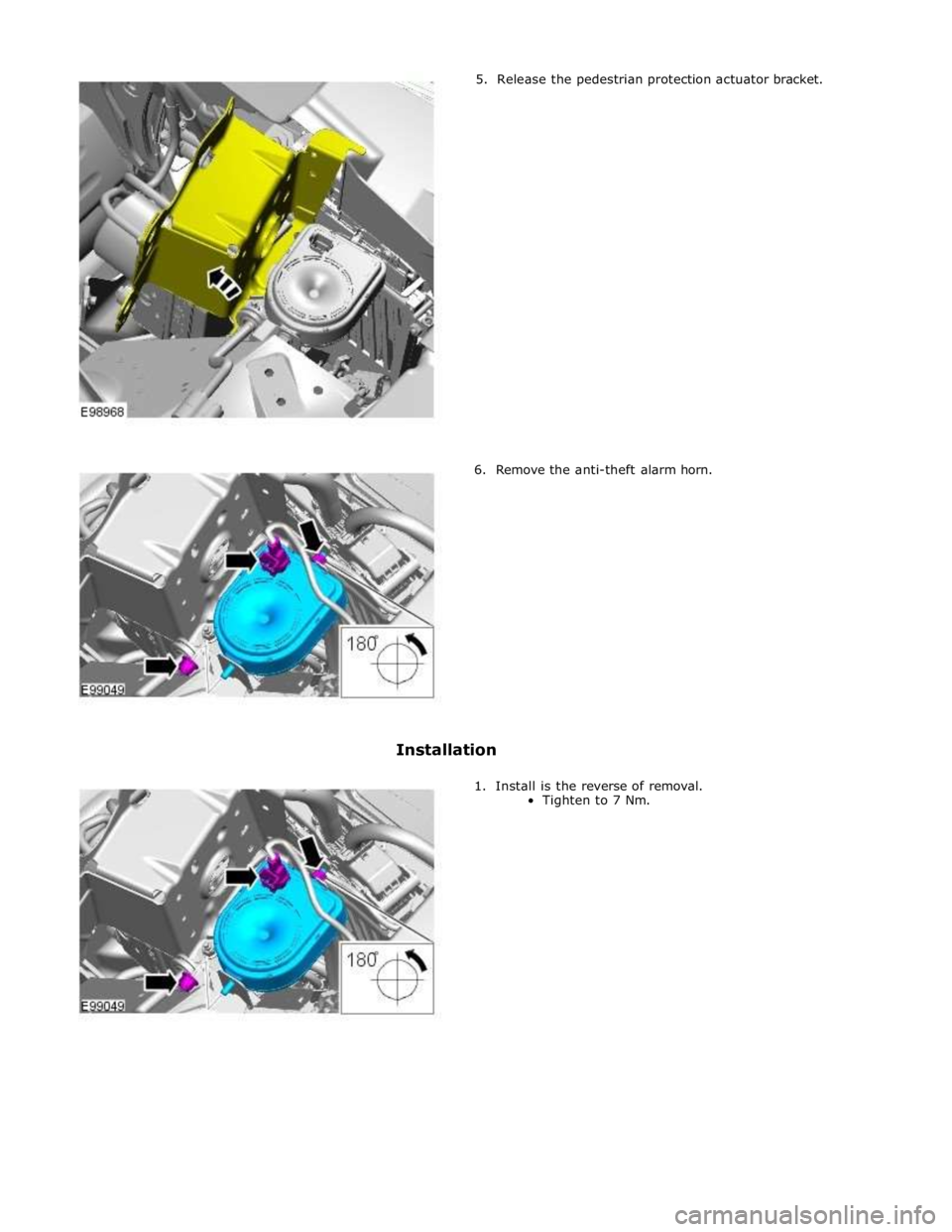
5. Release the pedestrian protection actuator bracket.
6. Remove the anti-theft alarm horn.
Installation
1. Install is the reverse of removal.
Tighten to 7 Nm.
Page 2167 of 3039

10 Diagnostic socket 11 Pedestrian protection control module 12 Electric steering column lock 13 TCM 14 ABS (anti-lock brake system) module COMPONENT LOCATION - MOST
Item Description NOTE: LHD vehicle shown 1 Touch Screen Display (TSD) 2 Integrated audio module 3 Entertainment system control module 4 Digital Audio Broadcast (DAB)/Satellite Digital Audio Radio System (SDARS) 5 Multimedia module
Page 2170 of 3039
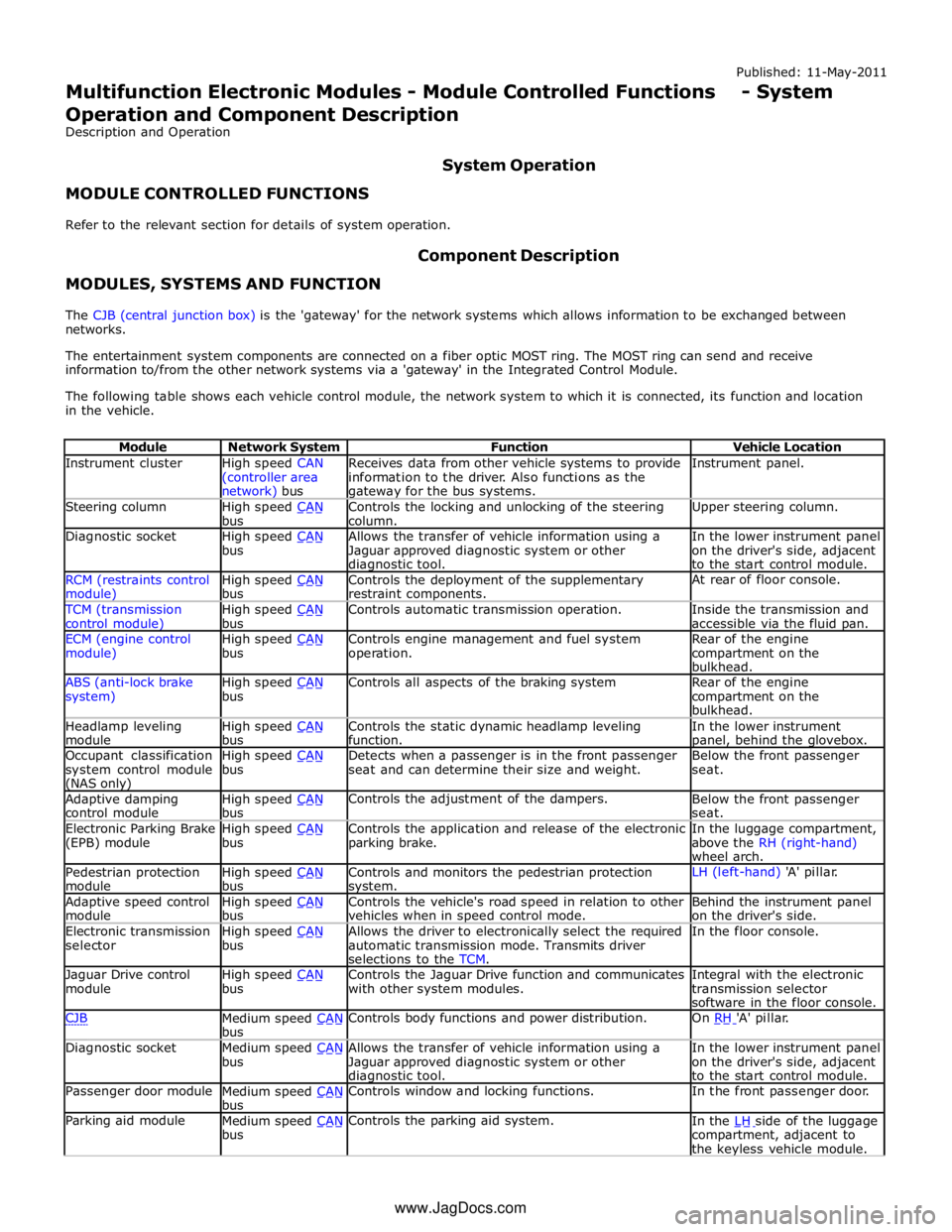
Instrument cluster
High speed CAN
(controller area network) bus Receives data from other vehicle systems to provide
information to the driver. Also functions as the gateway for the bus systems. Instrument panel. Steering column
High speed CAN bus Controls the locking and unlocking of the steering
column. Upper steering column. Diagnostic socket
High speed CAN bus Allows the transfer of vehicle information using a
Jaguar approved diagnostic system or other diagnostic tool. In the lower instrument panel
on the driver's side, adjacent
to the start control module. RCM (restraints control module) High speed CAN bus Controls the deployment of the supplementary
restraint components. At rear of floor console. TCM (transmission
control module) High speed CAN bus Controls automatic transmission operation.
Inside the transmission and
accessible via the fluid pan. ECM (engine control
module) High speed CAN bus Controls engine management and fuel system
operation. Rear of the engine
compartment on the
bulkhead. ABS (anti-lock brake
system) High speed CAN bus Controls all aspects of the braking system
Rear of the engine
compartment on the
bulkhead. Headlamp leveling
module High speed CAN bus Controls the static dynamic headlamp leveling
function. In the lower instrument panel, behind the glovebox. Occupant classification
system control module (NAS only) High speed CAN bus Detects when a passenger is in the front passenger
seat and can determine their size and weight. Below the front passenger
seat. Adaptive damping
control module High speed CAN bus Controls the adjustment of the dampers.
Below the front passenger
seat. Electronic Parking Brake
(EPB) module High speed CAN bus Controls the application and release of the electronic
parking brake. In the luggage compartment,
above the RH (right-hand)
wheel arch. Pedestrian protection
module High speed CAN bus Controls and monitors the pedestrian protection system. LH (left-hand) 'A' pillar. Adaptive speed control
module High speed CAN bus Controls the vehicle's road speed in relation to other
vehicles when in speed control mode. Behind the instrument panel
on the driver's side. Electronic transmission
selector High speed CAN bus Allows the driver to electronically select the required
automatic transmission mode. Transmits driver
selections to the TCM. In the floor console. Jaguar Drive control
module High speed CAN bus Controls the Jaguar Drive function and communicates
with other system modules. Integral with the electronic
transmission selector
software in the floor console. CJB
Medium speed CAN bus Controls body functions and power distribution. On RH 'A' pillar. Diagnostic socket
Medium speed CAN bus Allows the transfer of vehicle information using a
Jaguar approved diagnostic system or other diagnostic tool. In the lower instrument panel
on the driver's side, adjacent
to the start control module. Passenger door module
Medium speed CAN bus Controls window and locking functions. In the front passenger door. Parking aid module
Medium speed CAN bus Controls the parking aid system.
In the LH side of the luggage compartment, adjacent to
the keyless vehicle module. www.JagDocs.com
Page 2197 of 3039
Front End Body Panels - Hood
Removal and Installation Published: 11-May-2011
Removal
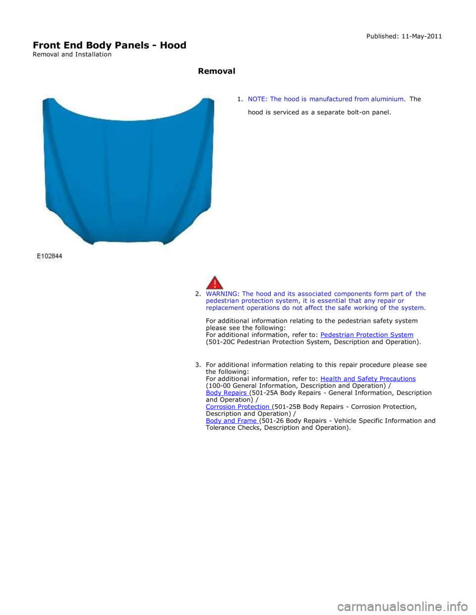
1. NOTE: The hood is manufactured from aluminium. The
hood is serviced as a separate bolt-on panel.
2. WARNING: The hood and its associated components form part of the
pedestrian protection system, it is essential that any repair or
replacement operations do not affect the safe working of the system.
For additional information relating to the pedestrian safety system
please see the following:
For additional information, refer to: Pedestrian Protection System (501-20C Pedestrian Protection System, Description and Operation).
3. For additional information relating to this repair procedure please see
the following:
For additional information, refer to: Health and Safety Precautions (100-00 General Information, Description and Operation) /
Body Repairs (501-25A Body Repairs - General Information, Description and Operation) /
Corrosion Protection (501-25B Body Repairs - Corrosion Protection, Description and Operation) /
Body and Frame (501-26 Body Repairs - Vehicle Specific Information and Tolerance Checks, Description and Operation).
Page 2200 of 3039
Installation
1. NOTES:
If the hood hinges are deformed as a result of the pedestrian
protection system deployment, they will need to be replaced.
This step requires the aid of another technician.
Offer up the panel and loosely install the hood hinge retaining nuts.
2. Check alignment, if correct, proceed to next step, if not, rectify and
recheck before proceeding.
3. Tighten the hood hinge retaining nuts to 17 Nm and connect the struts
and secure with the clips.
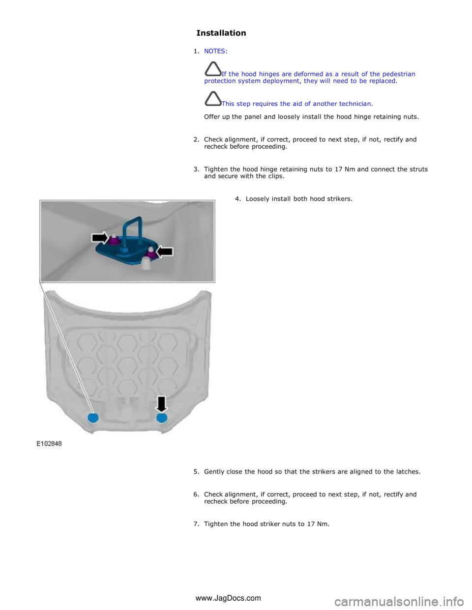
4. Loosely install both hood strikers.
5. Gently close the hood so that the strikers are aligned to the latches.
6. Check alignment, if correct, proceed to next step, if not, rectify and
recheck before proceeding.
7. Tighten the hood striker nuts to 17 Nm. www.JagDocs.com
Page 2450 of 3039

Safety Belt System (501-20A Safety Belt System, Description and Operation), Air Bag and Safety Belt Pretensioner Supplemental Restraint System (SRS) (501-20B Supplemental Restraint System, Description and Operation),
Pedestrian Protection System (501-20C Pedestrian Protection System, Description and Operation).
Page 2580 of 3039
Bumpers - Front Bumper
Removal and Installation Published: 11-May-2011
Removal
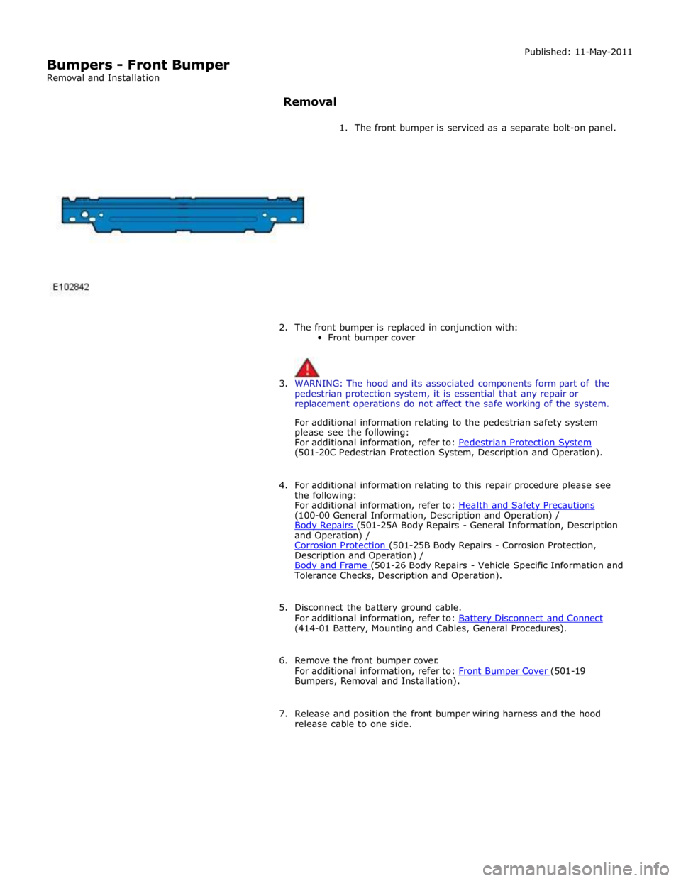
1. The front bumper is serviced as a separate bolt-on panel.
2. The front bumper is replaced in conjunction with:
Front bumper cover
3. WARNING: The hood and its associated components form part of the
pedestrian protection system, it is essential that any repair or
replacement operations do not affect the safe working of the system.
For additional information relating to the pedestrian safety system
please see the following:
For additional information, refer to: Pedestrian Protection System (501-20C Pedestrian Protection System, Description and Operation).
4. For additional information relating to this repair procedure please see
the following:
For additional information, refer to: Health and Safety Precautions (100-00 General Information, Description and Operation) /
Body Repairs (501-25A Body Repairs - General Information, Description and Operation) /
Corrosion Protection (501-25B Body Repairs - Corrosion Protection, Description and Operation) /
Body and Frame (501-26 Body Repairs - Vehicle Specific Information and Tolerance Checks, Description and Operation).
5. Disconnect the battery ground cable.
For additional information, refer to: Battery Disconnect and Connect (414-01 Battery, Mounting and Cables, General Procedures).
6. Remove the front bumper cover.
For additional information, refer to: Front Bumper Cover (501-19 Bumpers, Removal and Installation).
7. Release and position the front bumper wiring harness and the hood
release cable to one side.
Page 2681 of 3039

1 RH (right-hand) hood actuator 2 Pedestrian protection system control module 3 LH (left-hand) hood actuator 4 LH accelerometer 5 RH accelerometer
Page 2682 of 3039

Published: 11-May-2011
Pedestrian Protection System - Pedestrian Protection System - Overview
Description and Operation
OVERVIEW
WARNING: All pyrotechnic devices are dangerous. Before performing any procedures on any pyrotechnic device, read all
information contained within the Standard Workshop Practices section of this manual.
Refer to: Standard Workshop Practices (100-00 General Information, Description and Operation).
The pedestrian protection system is designed to mitigate injuries in a pedestrian collision with the vehicle. It does this by
utilizing a pair of pyrotechnic actuators to lift the hood away from the engine, creating a cushioned impact between the
pedestrian and the vehicle.
The pedestrian protection system also includes passive protection integrated into the bumper system and bonnet structure.
WARNING: Do not fit any non-Jaguar approved accessories to the vehicle.
NOTE: The pedestrian protection system operates independently from the SRS (supplemental restraint system).
Page 2683 of 3039

Published: 11-May-2011
Pedestrian Protection System - Pedestrian Protection System - System
Operation and Component Description
Description and Operation
Control Diagram
NOTE: A = Hardwired; D = High speed CAN (controller area network) bus; N = Medium speed CAN bus
Item Description 1 Battery 2 CJB (central junction box) 3 Instrument cluster 4 LH (left-hand) hood actuator 5 RH (right-hand) hood actuator 6 Pedestrian protection system control module