display JAGUAR XFR 2010 1.G Workshop Manual
[x] Cancel search | Manufacturer: JAGUAR, Model Year: 2010, Model line: XFR, Model: JAGUAR XFR 2010 1.GPages: 3039, PDF Size: 58.49 MB
Page 3 of 3039

Diagnostic Trouble Code (DTC) IndexDTC: Occupant Classification System (OCS)
Diagnostic Trouble Code (DTC) IndexDTC: Parking Aid Module (PAM)
Diagnostic Trouble Code (DTC) IndexDTC: Pedestrian Protection System Control Module (PPSCM)
Diagnostic Trouble Code (DTC) IndexDTC: Rear Differential Control Module (RDCM)
Diagnostic Trouble Code (DTC) IndexDTC: Rear Junction Box (RJB)
Diagnostic Trouble Code (DTC) IndexDTC: Remote Keyless Entry Module (RFA)
Diagnostic Trouble Code (DTC) IndexDTC: Restraints Control Module (RCM)
Diagnostic Trouble Code (DTC) IndexDTC: Satellite Digital Audio Radio System Module (SARM)
Diagnostic Trouble Code (DTC) IndexDTC: Speed Control Module (CCM)
Diagnostic Trouble Code (DTC) IndexDTC: Steering Column Lock Module (VIM)
Diagnostic Trouble Code (DTC) IndexDTC: Television Module (TVM)
Diagnostic Trouble Code (DTC) IndexDTC: Tire Pressure Monitoring System Module (TPM)
Diagnostic Trouble Code (DTC) IndexDTC: Touch Screen Display (FCDIM)
Diagnostic Trouble Code (DTC) IndexVehicles With: 6HP28 6-Speed Automatic Transmission, DTC:
Transmission Control Module (TCM)
Diagnostic Trouble Code (DTC) IndexDTC: Transmission Shift Module (GSM)
Diagnostic Trouble Code (DTC) IndexDTC: Portable Audio Interface Control Module (PAICM)
Diagnostic Trouble Code (DTC) IndexDTC: Hybrid Digital Radio Control Module (HDRCM)
Diagnostic Trouble Code (DTC) IndexDTC: Infotainment Control Module (ICM)
Diagnostic Trouble Code (DTC) IndexDTC: Telephone Module (TEL)100-01: Identification Codes
Description and OperationIdentification Codes100-02: Jacking and Lifting
Description and OperationJacking
Lifting100-04: Noise, Vibration and Harshness
Description and OperationNoise, Vibration and Harshness (NVH)Diagnosis and TestingNoise, Vibration and Harshness (NVH)General ProceduresExhaust System Neutralizing2: Chassis
204: Suspension
204-00: Suspension System - General InformationSpecificationDiagnosis and TestingSuspension SystemGeneral ProceduresCamber and Caster Adjustment
Page 22 of 3039

Operation and
Component DescriptionCellular PhoneComponent
Location
Overview
System Operation
and Component DescriptionNavigation SystemComponent Location
Overview
System Operation and Component DescriptionVideo SystemComponent
Location
Overview
System Operation
and Component DescriptionDiagnosis and TestingInformation and Entertainment SystemRemoval and InstallationAudio Unit
Audio Unit Antenna Amplifier
Audio and Climate Control Assembly
Front Door Speaker
Information and Entertainment Display
Information and Entertainment Module
Instrument Panel Speaker
Rear Door Speaker
Steering Wheel Audio Controls
Subwoofer Amplifier
Subwoofer Speaker
Satellite Radio Tuner415-01B: Information and Entertainment System - DTC: Audio Input Control Module
Diagnosis and TestingAudio Input Control Module417: Lighting
417-01: Exterior LightingSpecificationDescription and OperationComponent Location
Overview
System Operation and Component DescriptionDiagnosis and TestingHeadlampsGeneral ProceduresHeadlamp Adjustment (86.40.18)
Page 54 of 3039

Hydrofluorocarbon HFC High tension HT Hydrocarbon HC Idle Air Control IAC
Stepper motor driven device which varies the volume of air by-passing the
throttle to maintain the programmed idle speed Intake Air Temperature IAT Temperature of intake air Inertia Fuel Shut-off IFS
An inertia system that shuts off the fuel supply when activated by pre-determined force limits brought about by (e.g.) collision Input Shaft Speed ISS Indicates input shaft speed Key On, Engine Off KOEO Key On, Engine Running KOER Kilogram (mass) kg Kilogram (force) kgf Kilogram force per square
centimeter kgf/cm²
Kilometer km Kilometer per hour km/h Kilopascal kPa Kilovolt kV Knock Sensor KS
Sensor which detects the onset of detonation, and signals the ECM to
retard the ignition Liquid Crystal Display LCD
Optical digital display system, to which applied voltage varies the way the crystals reflect light, thereby modifying the display Lighting Control Module LCM Light Emitting Diode LED Low Tension LT
Primary circuit of the ignition system, linking the battery to the primary winding in the ignition coil Left-Hand LH Left-Hand Drive LHD Mass Air Flow MAF
System which provides information on the mass flow rate of the intake air
to the engine Manifold Absolute Pressure MAP Absolute pressure of the intake manifold air Manifold Absolute Pressure and Temperature MAPT
Malfunction Indicator Lamp MIL
A required on-board indicator to alert the driver of an emission related
malfunction Meter (measurement) m Metric (screw thread, e.g. M8) M Farad F Unit of electrical capacitance Millimeter mm Millimeter of mercury mmHg Millisecond ms Model year MY Newton N SI unit of force. 1 N = 0.2248 pounds force Newton Meter Nm SI unit of torque. Must not be confused with nm (nanometer) Negative Temperature
Coefficient NTC
Naturally aspirated N/A
Fuelling system using intake air at atmospheric pressure; not supercharged or turbocharged Noise, Vibration and Harshness NVH North American Specification NAS Vehicles for sale in the USA and Canadian markets On-Board Diagnostic OBD
A system that monitors some or all computer input and output control
signals. Signal(s) outside the pre-determined limits imply a fault in the system or a related system Oxides of Nitrogen Nox Oxygen Sensor O2S A sensor which detects oxygen content in the exhaust gases On-board Refuelling Vapour Recovery ORVR
Output State Control OSC Output Shaft Speed OSS Passenger Air Bag Deactivation PAD Pulsed Secondary Air Injection PAIR Passive Anti-Theft System PATS Positive Crankcase Ventilation PCV Parameter Identification PID
An index number referring to a parameter within a module without knowledge of its storage location Park/Neutral Position PNP Pulse Width Modulation PWM Programmable Electronic
Control Units System PECUS
Process whereby a common ECM is programmed on the production line to
suit the market requirements of a particular vehicle
Page 56 of 3039
General Information - Health and Safety Precautions
Description and Operation Published: 11-May-2011
The Health and Safety Precautions subsection refers to some commonly used chemicals and materials, hazards associated with
their use, and safety measures to be taken. Some of these chemicals may be included in the following list either in their own
right or as an ingredient in a sealer or adhesive.
Acids and Alkalis
See also Battery Acids.
e.g. caustic soda, sulphuric acid.
Used in batteries and cleaning materials.
Irritant and corrosive to the skin, eyes, nose and throat. Cause burns. Can destroy ordinary protective clothing.
Avoid splashes to the skin, eyes and clothing. Wear suitable protective impervious apron, gloves and goggles. Do not breath
mists.
Ensure access to eye wash bottles, shower and soap are readily available for splashing accidents.
Display Eye Hazard sign.
Air Bags
See also Fire, Chemical Materials - General
Highly flammable, explosive – observe No Smoking policy.
Used as a part of the Supplemental Restraint System (SRS), mounted in various positions around the vehicle.
The inflator contains a high-energetic propellant which, when ignited, produces a VERY HOT GAS (2500° C).
The gas generant used in air bags is Sodium Azide. This material is hermetically sealed in the module and is completely
consumed during deployment. No attempt should be made to open an air bag inflator as this will lead to the risk of exposure
to Sodium Azide. If a gas generator is ruptured, full protective clothing should be worn when dealing with the spillage.
After normal deployment, gloves and safety goggles should be worn during the handling process.
Deployed air bags should be disposed of in a plastic bag in accordance with local regulations at an approved chemical waste
site.
Following any direct contact with gas generant.
Wash affected areas thoroughly with water
Seek medical assistance if necessary
WARNING: To avoid accidental deployment and possible personal injury, the backup power supply must be depleted
before repairing or replacing any SRS components. To deplete the backup power supply energy, disconnect the battery negative
cable and wait for one minute. Failure to follow this instruction may result in personal injury.
NOTE: The storage, transportation, disposal and/or recycling of air bag modules must be carried out in accordance with all
applicable federal, state and local regulations including, but not limited to, those governing building and fire codes,
environmental protection, occupational health and safety and transportation.
Air Bags - Do's
Do store in an air bag safe when not installed to the vehicle.
Do store modules in an upright position
Do keep modules dry
Do carry modules with the cover side pointing away from the body
Do place modules with their cover side upwards
Do carefully inspect modules for damage
Do stand to one side when connecting modules
Do make sure all test equipment is properly calibrated and maintained
Do wash you hands after handling deployed air bags
Do wear safety glasses when carrying out repairs to the SRS or when handling an air bag module
Only carry out a system test with the air bag modules fully installed
Do inspect the condition of the impact sensor mounting bracket and sensor flylead if the vehicle has been involved in
an impact. Replace if damaged, even if there has been no deployment.
Air Bags - Do Nots
Do not store highly flammable material together with modules or gas generators
Do not store gas generators at temperatures exceeding 80° C
Page 66 of 3039
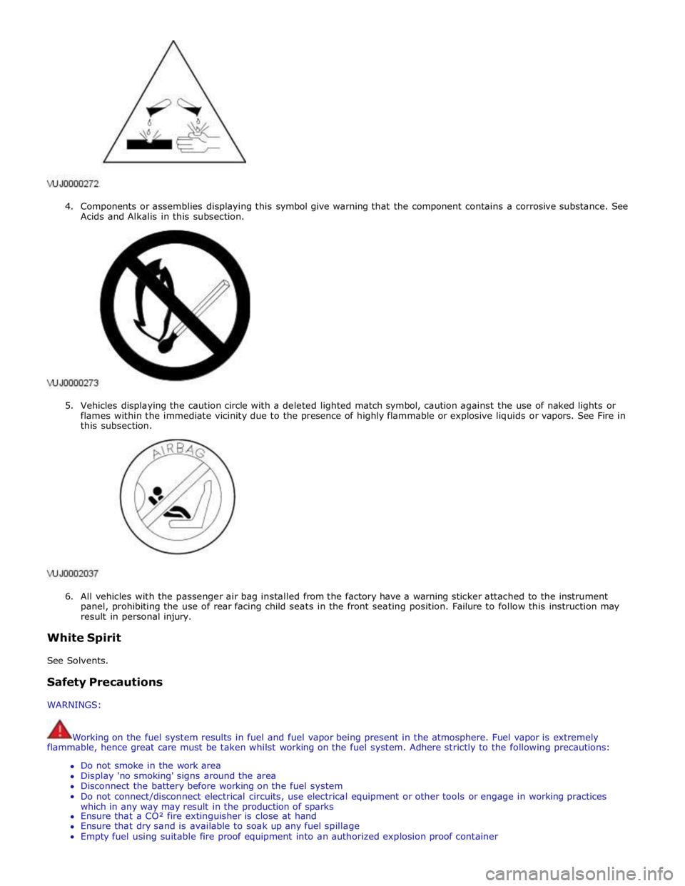
4. Components or assemblies displaying this symbol give warning that the component contains a corrosive substance. See
Acids and Alkalis in this subsection.
5. Vehicles displaying the caution circle with a deleted lighted match symbol, caution against the use of naked lights or
flames within the immediate vicinity due to the presence of highly flammable or explosive liquids or vapors. See Fire in
this subsection.
6. All vehicles with the passenger air bag installed from the factory have a warning sticker attached to the instrument
panel, prohibiting the use of rear facing child seats in the front seating position. Failure to follow this instruction may
result in personal injury.
White Spirit
See Solvents.
Safety Precautions
WARNINGS:
Working on the fuel system results in fuel and fuel vapor being present in the atmosphere. Fuel vapor is extremely
flammable, hence great care must be taken whilst working on the fuel system. Adhere strictly to the following precautions:
Do not smoke in the work area
Display 'no smoking' signs around the area
Disconnect the battery before working on the fuel system
Do not connect/disconnect electrical circuits, use electrical equipment or other tools or engage in working practices
which in any way may result in the production of sparks
Ensure that a CO² fire extinguisher is close at hand
Ensure that dry sand is available to soak up any fuel spillage
Empty fuel using suitable fire proof equipment into an authorized explosion proof container
Page 131 of 3039
Published: 17-Apr-2014
General Information - Diagnostic Trouble Code (DTC) Index DTC: Blind Spot Monitoring System Module (SODL/SODR)
Description and Operation
Blind Spot Monitoring System Module (SODL/SODR)
CAUTION: Diagnosis by substitution from a donor vehicle is NOT acceptable. Substitution of control modules does not
guarantee confirmation of a fault and may also cause additional faults in the vehicle being checked and/or the donor vehicle.
NOTES:
If the control module or a component is suspect and the vehicle remains under manufacturer warranty, refer to the
Warranty Policy and Procedures manual, or determine if any prior approval programme is in operation, prior to the installation
of a new module/component.
Generic scan tools may not read the codes listed, or may read only 5-digit codes. Match the 5 digits from the scan tool to
the first 5 digits of the 7-digit code listed to identify the fault (the last 2 digits give extra information read by the
manufacturer approved diagnostic system).
When performing voltage or resistance tests, always use a digital multimeter (DMM) accurate to three decimal places,
and with an up-to-date calibration certificate. When testing resistance, always take the resistance of the DMM leads into
account.
Check and rectify basic faults before beginning diagnostic routines involving pinpoint tests.
If DTCs are recorded and, after performing the pinpoint tests a fault is not present, an intermittent concern may be the
cause. Always check for loose connections and corroded terminals.
Where an 'on demand self-test' is referred to, this can be accessed via the 'DTC Monitor' tab on the manufacturers
approved diagnostic system.
Check DDW for open campaigns. Refer to the corresponding bulletins and SSMs which may be valid for the specific
customer complaint and carry out the recommendations as required.
The table below lists all Diagnostic Trouble Codes (DTCs) that could be logged in the Blind Spot Monitoring System Module, for
additional Diagnosis and Testing information refer to the relevant Diagnosis and Testing Section.
For additional information, refer to: Warning Devices (413-09 Warning Devices, Diagnosis and Testing).
DTC Description Possible Causes Action B11C9-11
Driver Display Status
LED - Circuit short to
ground
Circuit short to ground
Refer to the electrical circuit diagrams and check
driver display status LED circuit for short to
ground B11C9-15
Driver Display Status
LED - Circuit short to
battery or open
Circuit short to power or
open circuit
Refer to the electrical circuit diagrams and check
driver display status LED circuit for short to
ground B11D6-11
Driver Display Alert LED -
Circuit short to ground
Circuit short to ground
Refer to the electrical circuit diagrams and check
driver display status LED circuit for short to
ground B11D6-15
Driver Display Alert LED -
Circuit short to battery
or open
Circuit short to power or
open circuit
Refer to the electrical circuit diagrams and check
driver display status LED circuit for short to
ground U0010-00
Medium Speed CAN
Communication Bus - No
sub type information
No sub type information
Refer to the electrical circuit diagrams and check
the power and ground connections to the module.
Using the manufacturer approved diagnostic
system, complete a CAN network integrity test.
Refer to the electrical circuit diagrams and check
Page 237 of 3039

DTC Description Possible Causes Action B1A89-12
Satellite Antenna -
Circuit short to
battery
Satellite antenna circuit -
short to power
Refer to the electrical circuit diagrams and check
satellite antenna circuit for short circuit to power. Repair
wiring harness as required. Clear DTC and retest B1A89-13
Satellite Antenna -
Circuit open
Satellite antenna circuit -
open circuit, high
resistance
Refer to the electrical circuit diagrams and check
satellite antenna circuit for open circuit, high
resistance. Repair wiring harness as required. Clear DTC
and retest U3000-04
Control Module -
System internal
failures
System internal failure
Check and install a new satellite radio module as
required. Refer to the warranty policy and procedures
manual, or determine if any prior approval programme is
in operation, prior to the installation of a new
module/component U3000-4A Control Module -
Satellite radio module -
Using the manufacturer approved diagnostic system Incorrect component Incorrect component select the vehicle configuration main menu>vehicle installed installed configuration>display and modify the vehicle Car configuration configuration file data mismatch Check update as required U3000-55
Control Module -
Not configured
Satellite radio module -
Incorrect component
installed
Incorrect car configuration
file data received
Using the manufacturer approved diagnostic system
select the vehicle configuration main menu>select
configure existing modules menu and program the
satellite radio module U3000-87
Control Module -
Missing message
The satellite radio module
has not received the
configuration file
Master module not
transmitting configuration
file
Using the manufacturer approved diagnostic system
check that the satellite radio module is configured
correctly
Check that the configuration file is being transmitted by
the master module
Using the manufacturer approved diagnostic system,
complete a MOST network integrity test U3000-98
Control Module -
Component or
system over
temperature
Satellite radio module
cooling vents obstructed
Wiring harness fault
Internal electronic failure
Check for possible causes of the satellite radio module
overheating. Check that the ventilation is not
obstructed
Check for short circuit related DTCs. Refer to the
electrical circuit diagrams and check ground circuit for
high resistance. Check antenna circuit for short to power
or ground. Repair wiring harness as required. Clear DTC
and retest
Check for internal electronic failure related DTCs
If fault persists, check and install a new satellite radio
module. Refer to the warranty policy and procedures
manual, or determine if any prior approval programme is
in operation, prior to the installation of a new
module/component U3003-62
Battery Voltage -
Signal compare
failure
Signal compare failure
Satellite radio module
voltage differs more than
±2V compared to rear
junction box voltage
Refer to relevant section of workshop manual and
battery care manual. Check battery state of charge and
starting/charging system performance. Check power
supply circuit from rear junction box to satellite radio
module
Refer to electrical circuit diagrams and check the power
and ground supply circuits to the module. Repair wiring
harness as required. Clear DTC and retest
Page 251 of 3039
Published: 12-May-2014
General Information - Diagnostic Trouble Code (DTC) Index DTC: Touch
Screen Display (FCDIM)
Description and Operation
Touch Screen (TS)
CAUTION: Diagnosis by substitution from a donor vehicle is NOT acceptable. Substitution of control modules does not
guarantee confirmation of a fault, and may also cause additional faults in the vehicle being tested and/or the donor vehicle.
NOTES:
If a control module or a component is suspect and the vehicle remains under manufacturer warranty, refer to the Warranty
Policy and Procedures manual, or determine if any prior approval programme is in operation, prior to the installation of a new
module/component.
Generic scan tools may not read the codes listed, or may read only 5-digit codes. Match the 5 digits from the scan tool to
the first 5 digits of the 7-digit code listed to identify the fault (the last 2 digits give extra information read by the
manufacturer-approved diagnostic system).
When performing voltage or resistance tests, always use a digital multimeter accurate to three decimal places, and with
an up-to-date calibration certificate. When testing resistance always take the resistance of the digital multimeter leads into
account.
Check and rectify basic faults before beginning diagnostic routines involving pinpoint tests.
Inspect connectors for signs of water ingress, and pins for damage and/or corrosion.
If DTCs are recorded and, after performing the pinpoint tests, a fault is not present, an intermittent concern may be the
cause. Always check for loose connections and corroded terminals.
Check DDW for open campaigns. Refer to the corresponding bulletins and SSMs which may be valid for the specific
customer complaint and carry out the recommendations as required.
The table below lists all Diagnostic Trouble Codes (DTCs) that could be logged in the Touch Screen (TS). For additional
diagnosis and testing information, refer to the relevant Diagnosis and Testing section in the workshop manual.
For additional information, refer to: Information and Entertainment System (415-00 Information and Entertainment System - General Information, Diagnosis and Testing).
DTC Description Possible Causes Action B100E-25
Video Input 'A' - Signal
shape/waveform
failure
ODST Only - TV video
synch mis-match
Carry out any pinpoint tests associated with this DTC
using the manufacturer approved diagnostic system B100F-25
Video Input 'B' - Signal
shape/waveform
failure
ODST Only - Reverse
Camera video synch
mis-match
Carry out any pinpoint tests associated with this DTC
using the manufacturer approved diagnostic system U1A01-01
Communication Link -
General electrical
failure
ODST Only - cable
from navigation
module not correctly
installed
Carry out any pinpoint tests associated with this DTC
using the manufacturer approved diagnostic system.
Check electrical harness from navigation module is
correctly installed U1A01-15
Communication Link -
Circuit short to battery
or open
TSD to navigation
module circuit - short
to power, open circuit
Carry out any pinpoint tests associated with this DTC
using the manufacturer approved diagnostic system.
Refer to the electrical circuit diagrams and check TSD to
navigation module circuit for short to power, open circuit U1A4B-48
Control Module
Processor B -
Supervision software
failure
Supervision software
failure
Re-configure the TSD using the manufacturer approved
diagnostic system www.JagDocs.com
Page 260 of 3039

DTC Description Possible Causes Action suspect. P0783-77
3-4 Shift - Commanded
position not reachable
Gear Ratio Monitoring.
Mechanical Failures
Check and correct oil level. Clear DTC. If code
re-detects suspect Transmission (mechanical)
internal fault. Install a new Transmission as
required, refer to the warranty policy and
procedures manual if a module/component is
suspect. P0784-07
4-5 Shift - Mechanical
Failures
Gear Ratio Monitoring.
Mechanical Failures
Check and correct oil level. Clear DTC. If code
re-detects suspect Transmission (mechanical)
internal fault. Install a new Transmission as
required, refer to the warranty policy and
procedures manual if a module/component is
suspect. P0784-77
4-5 Shift - Commanded
position not reachable
Gear Ratio Monitoring.
Mechanical Failures
Check and correct oil level. Clear DTC. If code
re-detects suspect Transmission (mechanical)
internal fault. Install a new Transmission as
required, refer to the warranty policy and
procedures manual if a module/component is
suspect. P0798-1A
Pressure Control Solenoid
C Electrical - Circuit
Resistance Below Threshold
Pressure control solenoid
C Circuit resistance below
threshold
Suspect the Transmission Control Module. Install a
new Transmission Control Module as required,
refer to the warranty policy and procedures manual
if a module/component is suspect. P0798-1E
Pressure Control Solenoid
C Electrical - Circuit Short
to Ground
Pressure control solenoid
C electrical circuit short
to ground
Suspect the Transmission Control Module. Install a
new Transmission Control Module as required,
refer to the warranty policy and procedures manual
if a module/component is suspect. P0798-21
Pressure Control Solenoid
C Electrical - Signal
amplitude < minimum
Pressure Control Solenoid
C Electrical signal
amplitude < minimum
Suspect the Transmission Control Module. Install a
new Transmission Control Module as required,
refer to the warranty policy and procedures manual
if a module/component is suspect. P0814-62 Transmission Range
Display Circuit - Signal
compare failure
Transmission Range
Display Circuit signal
compare failure
Suspect the Transmission Control Module. Install a
new Transmission Control Module as required,
refer to the warranty policy and procedures manual
if a module/component is suspect. P0826-08
Up and Down Switch
circuit - Bus Signal
Message Failures
Invalid CAN signal from
Central Junction
Box/Instrument Cluster
Stuck Sprintronic switch
CAN bus circuit fault
Check Central Junction Box and Instrument Cluster
for stored DTCs. Check gear change switches for
correct operation. Refer to circuit diagrams and
check CAN bus for a circuit fault P0826-81
Up and Down Switch
Circuit - Invalid serial
data received
Invalid Can signal from
Central Junction Box /
Instrument Cluster
Stuck Sprintronic switch
CAN Bus Circuit fault
Check Central Junction Box and Instrument Cluster
for stored DTCs. Check Gear Change Switches for
correct operation. Refer to Circuit diagrams and
check CAN Bus for Circuit fault P0826-88
Up and Down Switch
Circuit - Bus off
Steering Wheel Module to
Central Junction Box /
Instrument Cluster LIN
Bus failure
Check Central Junction Box and Steering Wheel
Ice Switches for stored DTCs. Refer to Circuit
diagrams and check LIN Bus for Circuit fault P0829-07
5-6 Shift - Mechanical
Failures
Gear Ratio Monitoring.
Mechanical Failures
Check and correct oil level. Clear DTC. If code
re-detects suspect Transmission (mechanical)
internal fault. Install a new Transmission as
required, refer to the warranty policy and
procedures manual if a module/component is
suspect. www.JagDocs.com
Page 292 of 3039
1
Occupant number 2
Engine specification (Type/Capacity/Power) 3
VIN 4
Trade mark 5
Vehicle type 6
Gross vehicle weight 7
Date of manufacture 8
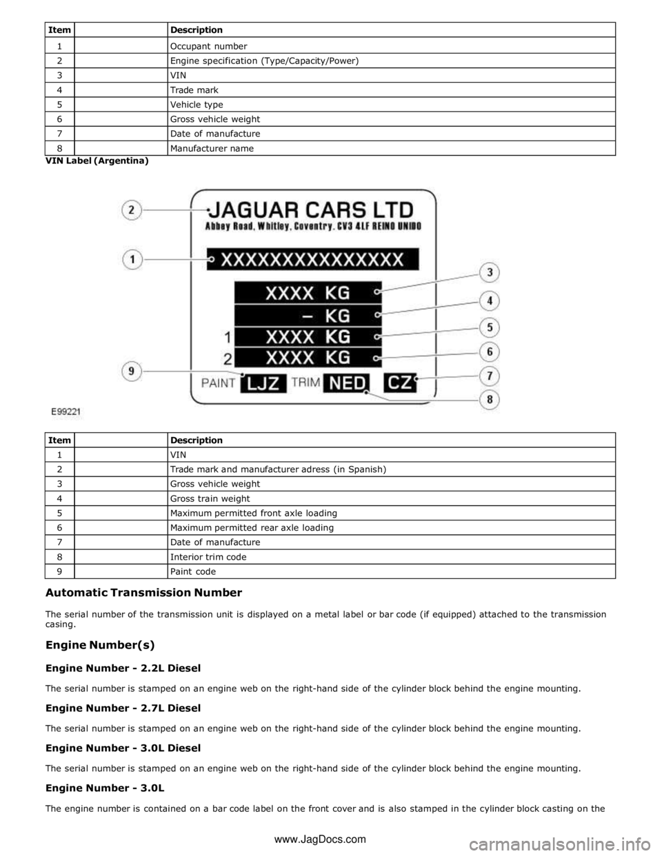
Manufacturer name VIN Label (Argentina)
Item
Description 1
VIN 2
Trade mark and manufacturer adress (in Spanish) 3
Gross vehicle weight 4
Gross train weight 5
Maximum permitted front axle loading 6
Maximum permitted rear axle loading 7
Date of manufacture 8
Interior trim code 9
Paint code Automatic Transmission Number
The serial number of the transmission unit is displayed on a metal label or bar code (if equipped) attached to the transmission
casing.
Engine Number(s)
Engine Number - 2.2L Diesel
The serial number is stamped on an engine web on the right-hand side of the cylinder block behind the engine mounting.
Engine Number - 2.7L Diesel
The serial number is stamped on an engine web on the right-hand side of the cylinder block behind the engine mounting.
Engine Number - 3.0L Diesel
The serial number is stamped on an engine web on the right-hand side of the cylinder block behind the engine mounting.
Engine Number - 3.0L
The engine number is contained on a bar code label on the front cover and is also stamped in the cylinder block casting on the www.JagDocs.com