Pedestrian JAGUAR XFR 2010 1.G Owner's Guide
[x] Cancel search | Manufacturer: JAGUAR, Model Year: 2010, Model line: XFR, Model: JAGUAR XFR 2010 1.GPages: 3039, PDF Size: 58.49 MB
Page 2797 of 3039

(100-00 General Information, Description and Operation) /
Body Repairs (501-25A Body Repairs - General Information, Description and Operation) /
Corrosion Protection (501-25B Body Repairs - Corrosion Protection, Description and Operation) /
Body and Frame (501-26 Body Repairs - Vehicle Specific Information and Tolerance Checks, Description and Operation).
5. Remove the fender apron panel front extension.
For additional information, refer to: Fender Apron Panel Front Extension (501-27 Front End Sheet Metal Repairs, Removal and Installation).
6. Remove the front fender support bracket.
For additional information, refer to: Front Fender Support Bracket (501-27 Front End Sheet Metal Repairs, Removal and Installation).
7. Remove the fender apron panel.
For additional information, refer to: Fender Apron Panel (501-27 Front End Sheet Metal Repairs, Removal and Installation).
8. Remove the engine, transmission / transaxle, front subframe and front
suspension, as an assembly.
For additional information, refer to: Engine (303-01A, Removal) /
Engine (303-01B Engine - V6 3.0L Petrol, Removal) / Engine (303-01D, Removal) /
Engine (303-01E, Removal) /
Transmission - 2.7L Diesel (307-01, Removal) /
Transmission - TDV6 3.0L Diesel (307-01B Automatic Transmission/Transaxle - TDV6 3.0L Diesel /V8 5.0L Petrol/V8 S/C 5.0L
Petrol, Removal) /
Transmission (307-01A Automatic Transmission/Transaxle - V6 3.0L Petrol, Removal) /
Transmission - 4.2L (307-01, Removal) /
Transmission - V8 5.0L Petrol/V8 S/C 5.0L Petrol (307-01B Automatic Transmission/Transaxle - TDV6 3.0L Diesel /V8 5.0L Petrol/V8 S/C 5.0L
Petrol, Removal) /
Front Shock Absorber (204-01 Front Suspension, Removal and Installation) /
Front Subframe - 2.7L Diesel (502-00, Removal and Installation) /
Front Subframe - V6 3.0L Petrol (502-00 Uni-Body, Subframe and Mounting System, Removal and Installation) /
Front Subframe - 4.2L, Vehicles Without: Supercharger (502-00, Removal
and Installation) /
Front Subframe - 4.2L, Vehicles With: Supercharger (502-00, Removal
and Installation).
9. Remove the pedestrian protection hood actuator.
For additional information, refer to: Pedestrian Protection Hood Actuator LH (501-20C Pedestrian Protection System, Removal and Installation) / Pedestrian Protection Hood Actuator RH (501-20C Pedestrian Protection System, Removal and Installation).
10. If the drivers side front side member and suspension top mount is to be
repaired, remove the brake master cylinder and reservoir.
For additional information, refer to: Brake Master Cylinder (206-06 Hydraulic Brake Actuation, Removal and Installation) /
Brake Fluid Reservoir (206-06 Hydraulic Brake Actuation, Removal and Installation).
11. If the drivers side front side member and suspension top mount is to be
repaired, remove the brake booster.
Page 2820 of 3039

Front End Sheet Metal Repairs - Hood Latch Panel
Removal and Installation
Removal Published: 11-May-2011
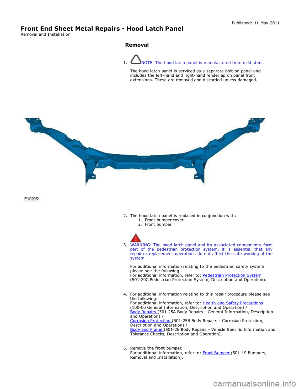
1. NOTE: The hood latch panel is manufactured from mild steel.
The hood latch panel is serviced as a separate bolt-on panel and
includes the left-hand and right-hand fender apron panel front
extensions. These are removed and discarded unless damaged.
2. The hood latch panel is replaced in conjunction with:
1. Front bumper cover
2. Front bumper
3. WARNING: The hood latch panel and its associated components form
part of the pedestrian protection system, it is essential that any
repair or replacement operations do not affect the safe working of the
system.
For additional information relating to the pedestrian safety system
please see the following:
For additional information, refer to: Pedestrian Protection System (501-20C Pedestrian Protection System, Description and Operation).
4. For additional information relating to this repair procedure please see
the following:
For additional information, refer to: Health and Safety Precautions (100-00 General Information, Description and Operation) /
Body Repairs (501-25A Body Repairs - General Information, Description and Operation) /
Corrosion Protection (501-25B Body Repairs - Corrosion Protection, Description and Operation) /
Body and Frame (501-26 Body Repairs - Vehicle Specific Information and Tolerance Checks, Description and Operation).
5. Remove the front bumper.
For additional information, refer to: Front Bumper (501-19 Bumpers, Removal and Installation).
Page 2846 of 3039

Ornamentation, Removal and Installation).
8. Remove the windshield glass.
For additional information, refer to: Windshield Glass (501-11 Glass, Frames and Mechanisms, Removal and Installation).
9. Remove the pedestrian protection hood actuator.
For additional information, refer to: Pedestrian Protection Hood Actuator LH (501-20C Pedestrian Protection System, Removal and Installation) / Pedestrian Protection Hood Actuator RH (501-20C Pedestrian Protection System, Removal and Installation).
10. Release and position the floor covering to one side.
11. Release and position the bulkhead insulating material to one side.
12. Release and position the inner rocker panel wiring harness to one side.
13. Remove the wheel and tire.
For additional information, refer to: Wheel and Tire (204-04 Wheels and Tires, Removal and Installation).
14. Remove the underfloor splash shield.
15. If the right-hand A-pillar outer panel is to be repaired, release and
position the underfloor wiring harness to one side.
16. Remove the front fender.
For additional information, refer to: Front Fender (501-27 Front End Sheet Metal Repairs, Removal and Installation).
17. Remove the front door.
For additional information, refer to: Front Door (501-03 Body Closures, Removal and Installation).
18. Remove the upper and lower front door hinges.
19. Remove the hood.
For additional information, refer to: Hood (501-02 Front End Body Panels, Removal and Installation).
20. Remove the hood hinge.