Subframe JAGUAR XFR 2010 1.G User Guide
[x] Cancel search | Manufacturer: JAGUAR, Model Year: 2010, Model line: XFR, Model: JAGUAR XFR 2010 1.GPages: 3039, PDF Size: 58.49 MB
Page 394 of 3039
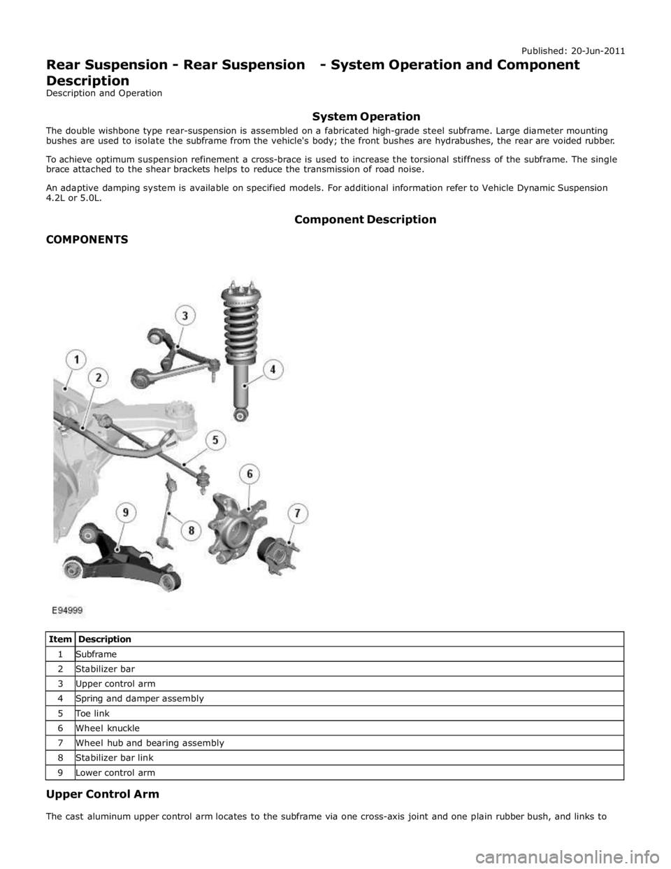
1 Subframe 2 Stabilizer bar 3 Upper control arm 4 Spring and damper assembly 5 Toe link 6 Wheel knuckle 7 Wheel hub and bearing assembly 8 Stabilizer bar link 9 Lower control arm Upper Control Arm
The cast aluminum upper control arm locates to the subframe via one cross-axis joint and one plain rubber bush, and links to
Page 395 of 3039

the aluminum wheel knuckle via an integral ball-joint.
Lower Control Arm
The aluminum lower arm locates to the subframe via one cross-axis joint and one plain rubber bush, and to the wheel knuckle
via a second plain rubber bush.
The rear of the control arm has mounting points for the damper and the stabilizer link.
Toe-Link
The toe-link is located between the wheel knuckle and brackets on the subframe.
The toe-link comprises an inner rod with integral axial ball joint. The inner ball joint has a threaded spigot which locates in a
bracket on the subframe and is secured with a locknut. The rod has an internal thread which accepts the outer rod.
The outer rod has a cross-axis joint at its outer end which is located in a clevis on the wheel knuckle, and is secured with a
bolt and locknut.
The length of the toe-link can be adjusted by rotating the inner rod. This allows for adjustment of the toe angle for the rear
wheel. Once set the inner rod can be locked in position by tightening a locknut on the outer rod against the inner rod.
Wheel Knuckle
The cast aluminum wheel knuckle attaches to:
the upper control arm via a ball-joint located in the arm,
the lower control arm via a plain rubber bush located in the arm,
the toe-link via a cross-axis joint located in the toe link.
The wheel knuckle also provides the mounting locations for the:
wheel hub assembly,
wheel bearing,
wheel speed sensor,
brake caliper,
and disc shield.
Stabilizer Bar
The solid construction stabilizer bar and bushes have been designed to provide particular characteristics in maintaining roll
rates, specifically in primary ride comfort. There are six derivatives of rear stabilizer bar, with different diameters, to support
the various powertrains:
V6 gasoline - 12.7 mm solid bar
V8 4.2L and 5.0L gasoline - 13.6 mm solid bar
V6 2.7L diesel -14.5 mm solid bar
V6 3.0L diesel - 14.5 mm solid bar
V6 3.0L diesel with Adaptive Damping – 16mm tubular
V8 4.2L gasoline supercharged – 16mm tubular
V8 5.0L gasoline supercharged
- SV8 - 17mm tubular
- XFR - 18mm tubular
The stabilizer bar is attached to the top of the subframe with two bushes and mounting brackets. The stabilizer bar has
crimped, 'anti-shuffle' collars pressed in position on the inside edges of the bushes. The collars prevent sideways movement of
the stabilizer bar.
Each end of the stabilizer bar curves rearward to attach to a ball joint on each stabilizer link. Each link is attached via a
second ball joint to a cast bracket on the lower control arm. The links allow the stabilizer bar to move with the wheel travel
providing maximum effectiveness.
Spring and Damper Assembly
The spring and damper assembly are attached to cast brackets on the lower control arms and to the vehicle body by four studs
secured by locking nuts. Dependant on vehicle model there are three types of coil spring and damper available:
a standard oil passive damper (All models except supercharged),
an adaptive damper, also known as Computer Active Technology Suspension (CATS) on 4.2L supercharged vehicles up to
2010MY, For additional information refer to Vehicle Dynamic Suspension 4.2L.
a continuously variable adaptive damper, also known as Adaptive Dynamics System on 5.0L supercharged vehicles from
2010MY. For additional information refer to Vehicle Dynamic Suspension 5.0L.
The dampers are a monotube design with a spring located by a circlip onto the damper tube. The lower end of the damper has
a spherical joint which locates in the lower control arm and is secured with a bolt.
The damper piston is connected to a damper rod which is sealed at its exit point from the damper body. The threaded outer
end of the damper rod locates through a hole in the top mount. A self locking nut secures the top mount to the damper rod.
The damper rod on the adaptive damper has an electrical connector on the outer end of the damper rod. www.JagDocs.com
Page 414 of 3039
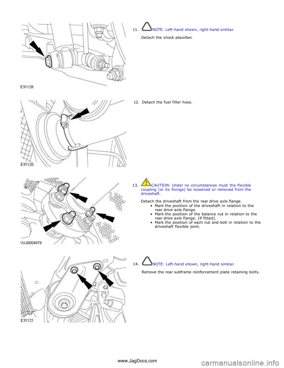
11.
12.
13.
14. NOTE: Left-hand shown, right-hand similar.
Detach the shock absorber.
Detach the fuel filler hose.
CAUTION: Under no circumstances must the flexible
coupling (or its fixings) be loosened or removed from the
driveshaft.
Detach the driveshaft from the rear drive axle flange.
Mark the position of the driveshaft in relation to the
rear drive axle flange.
Mark the position of the balance nut in relation to the
rear drive axle flange. (if fitted).
Mark the position of each nut and bolt in relation to the
driveshaft flexible joint.
NOTE: Left-hand shown, right-hand similar.
Remove the rear subframe reinforcement plate retaining bolts. www.JagDocs.com
Page 415 of 3039
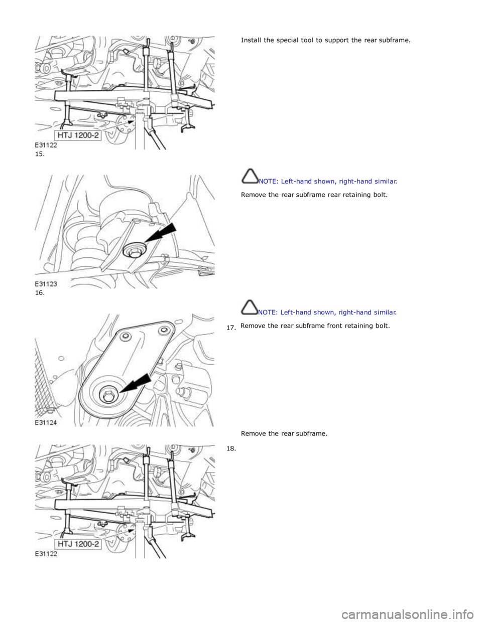
15.
16.
17.
18. Install the special tool to support the rear subframe.
NOTE: Left-hand shown, right-hand similar.
Remove the rear subframe rear retaining bolt.
NOTE: Left-hand shown, right-hand similar.
Remove the rear subframe front retaining bolt.
Remove the rear subframe.
Page 417 of 3039
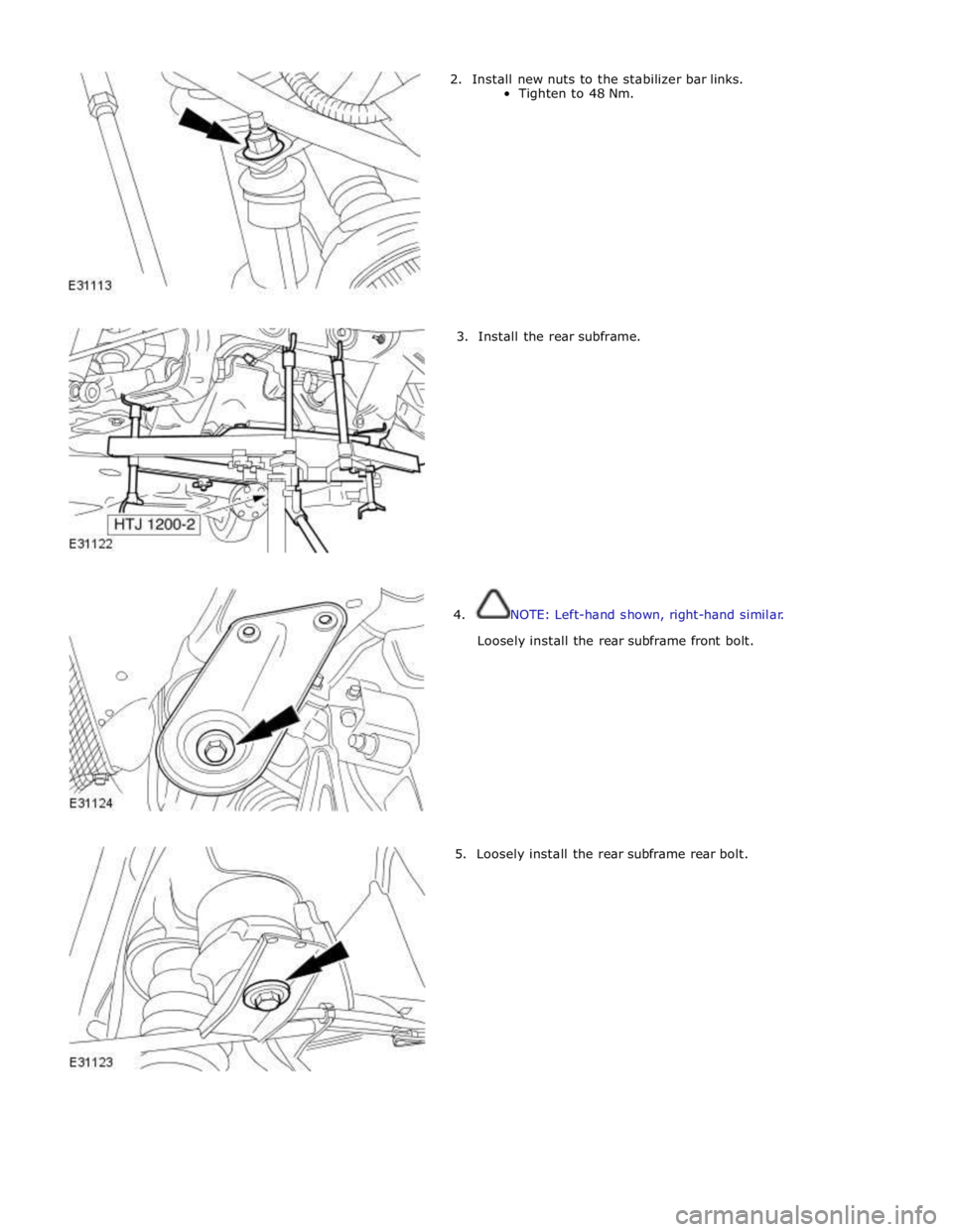
2. Install new nuts to the stabilizer bar links.
Tighten to 48 Nm.
3. Install the rear subframe.
4. NOTE: Left-hand shown, right-hand similar.
Loosely install the rear subframe front bolt.
5. Loosely install the rear subframe rear bolt.
Page 418 of 3039
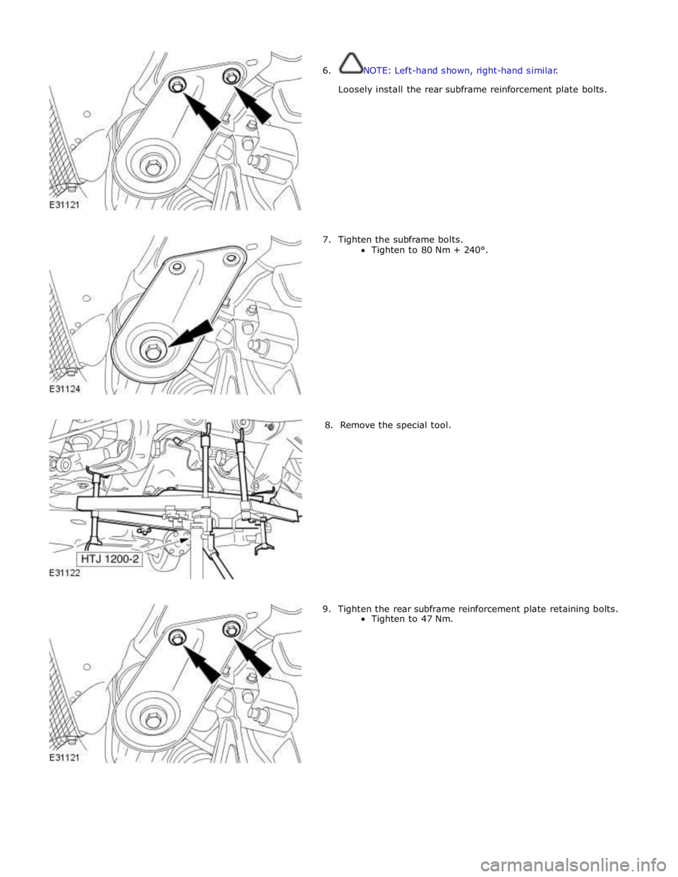
6. NOTE: Left-hand shown, right-hand similar.
Loosely install the rear subframe reinforcement plate bolts.
7. Tighten the subframe bolts.
Tighten to 80 Nm + 240°.
8. Remove the special tool.
9. Tighten the rear subframe reinforcement plate retaining bolts.
Tighten to 47 Nm.
Page 486 of 3039
2 Main piston 3 Tube 4 Bypass valve (closed) 5 Piston and rod assembly ACCELEROMETERS
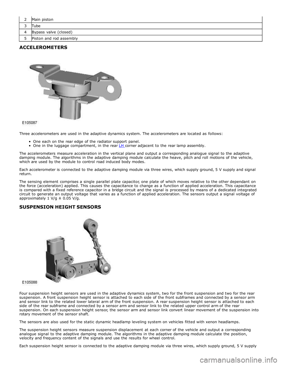
Three accelerometers are used in the adaptive dynamics system. The accelerometers are located as follows:
One each on the rear edge of the radiator support panel.
One in the luggage compartment, in the rear LH corner adjacent to the rear lamp assembly.
The accelerometers measure acceleration in the vertical plane and output a corresponding analogue signal to the adaptive
damping module. The algorithms in the adaptive damping module calculate the heave, pitch and roll motions of the vehicle,
which are used by the module to control road induced body modes.
Each accelerometer is connected to the adaptive damping module via three wires, which supply ground, 5 V supply and signal
return.
The sensing element comprises a single parallel plate capacitor, one plate of which moves relative to the other dependant on
the force (acceleration) applied. This causes the capacitance to change as a function of applied acceleration. This capacitance
is compared with a fixed reference capacitor in a bridge circuit and the signal is processed by means of a dedicated integrated
circuit to generate an output voltage that varies as a function of applied acceleration. The sensors output a signal voltage of
approximately 1 V/g ± 0.05 V/g.
SUSPENSION HEIGHT SENSORS
Four suspension height sensors are used in the adaptive dynamics system, two for the front suspension and two for the rear
suspension. A front suspension height sensor is attached to each side of the front subframes and connected by a sensor arm
and sensor link to the related lower lateral arm of the front suspension. A rear suspension height sensor is attached to each
side of the rear subframe and connected by a sensor arm and sensor link to the related upper control arm of the rear
suspension. On each suspension height sensor, the sensor arm and sensor link convert linear movement of the suspension into
rotary movement of the sensor shaft.
The sensors are also used for the static dynamic headlamp leveling system on vehicles fitted with xenon headlamps.
The suspension height sensors measure suspension displacement at each corner of the vehicle and output a corresponding
analogue signal to the adaptive damping module. The algorithms in the adaptive damping module calculate the position,
velocity and frequency content of the signals and use the results for wheel control.
Each suspension height sensor is connected to the adaptive damping module via three wires, which supply ground, 5 V supply
Page 509 of 3039
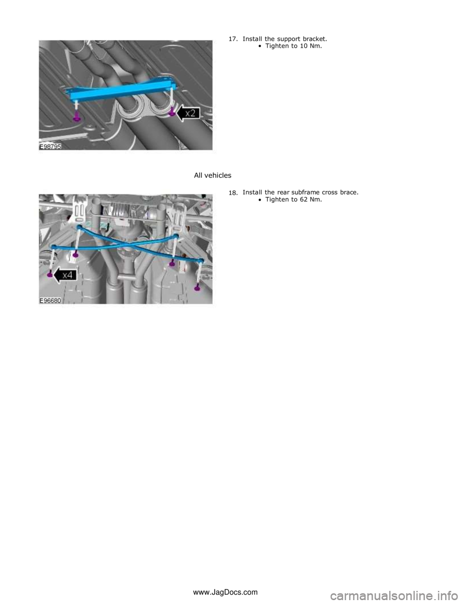
17. Install the support bracket.
Tighten to 10 Nm.
All vehicles
18. Install the rear subframe cross brace.
Tighten to 62 Nm. www.JagDocs.com
Page 585 of 3039
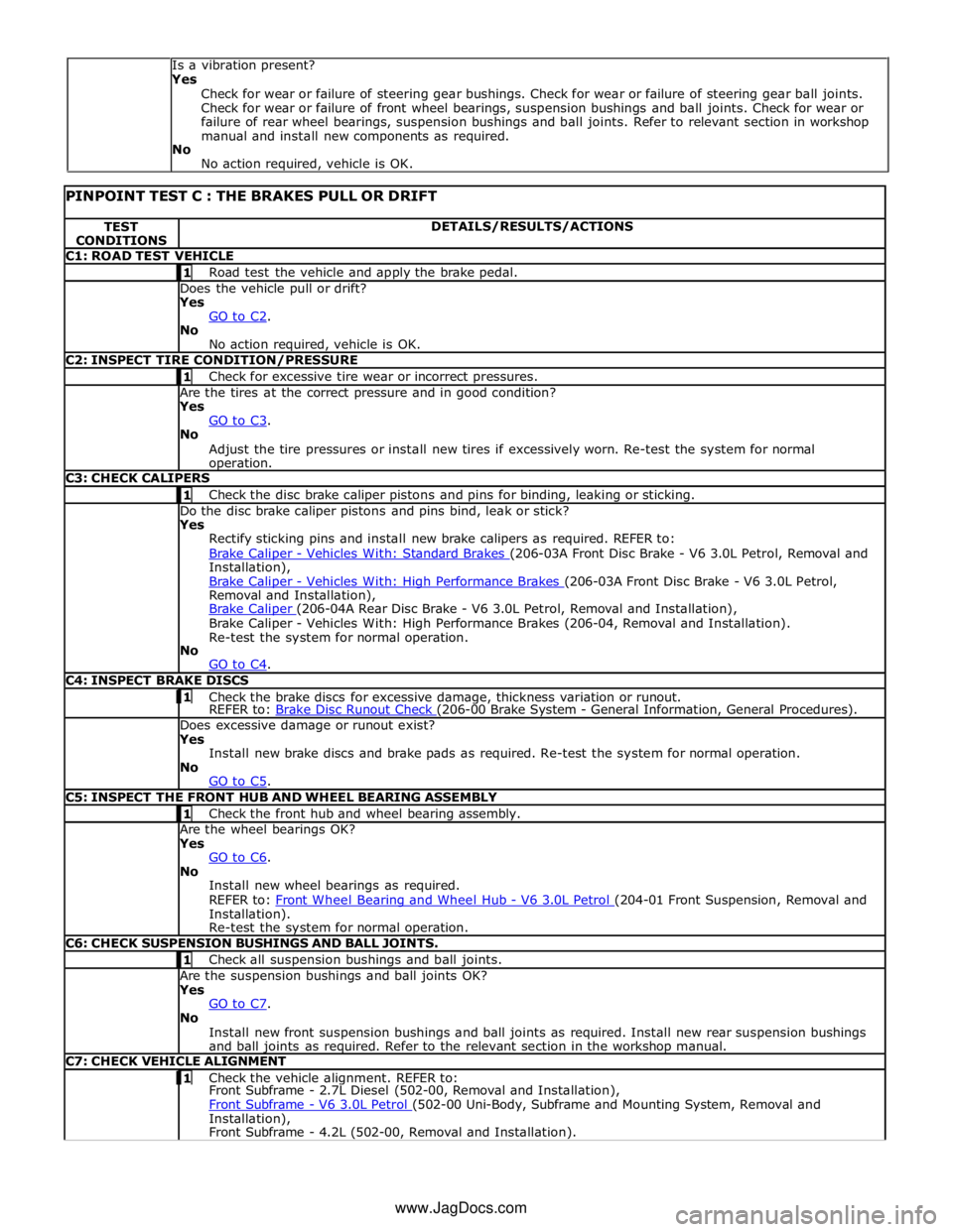
TEST
CONDITIONS DETAILS/RESULTS/ACTIONS C1: ROAD TEST VEHICLE 1 Road test the vehicle and apply the brake pedal. Does the vehicle pull or drift?
Yes
GO to C2. No
No action required, vehicle is OK. C2: INSPECT TIRE CONDITION/PRESSURE 1 Check for excessive tire wear or incorrect pressures. Are the tires at the correct pressure and in good condition?
Yes
GO to C3. No
Adjust the tire pressures or install new tires if excessively worn. Re-test the system for normal operation. C3: CHECK CALIPERS 1 Check the disc brake caliper pistons and pins for binding, leaking or sticking. Do the disc brake caliper pistons and pins bind, leak or stick?
Yes
Rectify sticking pins and install new brake calipers as required. REFER to:
Brake Caliper - Vehicles With: Standard Brakes (206-03A Front Disc Brake - V6 3.0L Petrol, Removal and Installation),
Brake Caliper - Vehicles With: High Performance Brakes (206-03A Front Disc Brake - V6 3.0L Petrol, Removal and Installation),
Brake Caliper (206-04A Rear Disc Brake - V6 3.0L Petrol, Removal and Installation), Brake Caliper - Vehicles With: High Performance Brakes (206-04, Removal and Installation).
Re-test the system for normal operation.
No
GO to C4. C4: INSPECT BRAKE DISCS 1 Check the brake discs for excessive damage, thickness variation or runout. REFER to: Brake Disc Runout Check (206-00 Brake System - General Information, General Procedures). Does excessive damage or runout exist?
Yes
Install new brake discs and brake pads as required. Re-test the system for normal operation.
No
GO to C5. C5: INSPECT THE FRONT HUB AND WHEEL BEARING ASSEMBLY 1 Check the front hub and wheel bearing assembly. Are the wheel bearings OK?
Yes
GO to C6. No
Install new wheel bearings as required.
REFER to: Front Wheel Bearing and Wheel Hub - V6 3.0L Petrol (204-01 Front Suspension, Removal and Installation).
Re-test the system for normal operation. C6: CHECK SUSPENSION BUSHINGS AND BALL JOINTS. 1 Check all suspension bushings and ball joints. Are the suspension bushings and ball joints OK?
Yes
GO to C7. No
Install new front suspension bushings and ball joints as required. Install new rear suspension bushings
and ball joints as required. Refer to the relevant section in the workshop manual. C7: CHECK VEHICLE ALIGNMENT 1 Check the vehicle alignment. REFER to: Front Subframe - 2.7L Diesel (502-00, Removal and Installation),
Front Subframe - V6 3.0L Petrol (502-00 Uni-Body, Subframe and Mounting System, Removal and Installation),
Front Subframe - 4.2L (502-00, Removal and Installation). Is a vibration present?
Yes
Check for wear or failure of steering gear bushings. Check for wear or failure of steering gear ball joints.
Check for wear or failure of front wheel bearings, suspension bushings and ball joints. Check for wear or
failure of rear wheel bearings, suspension bushings and ball joints. Refer to relevant section in workshop
manual and install new components as required.
No
No action required, vehicle is OK.
www.JagDocs.com
Page 586 of 3039
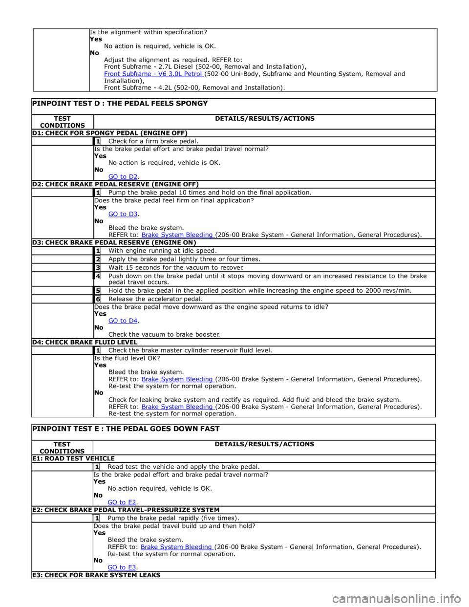
TEST
CONDITIONS DETAILS/RESULTS/ACTIONS D1: CHECK FOR SPONGY PEDAL (ENGINE OFF) 1 Check for a firm brake pedal. Is the brake pedal effort and brake pedal travel normal? Yes
No action is required, vehicle is OK.
No
GO to D2. D2: CHECK BRAKE PEDAL RESERVE (ENGINE OFF) 1 Pump the brake pedal 10 times and hold on the final application. Does the brake pedal feel firm on final application? Yes
GO to D3. No
Bleed the brake system.
REFER to: Brake System Bleeding (206-00 Brake System - General Information, General Procedures). D3: CHECK BRAKE PEDAL RESERVE (ENGINE ON) 1 With engine running at idle speed. 2 Apply the brake pedal lightly three or four times. 3 Wait 15 seconds for the vacuum to recover. 4 Push down on the brake pedal until it stops moving downward or an increased resistance to the brake pedal travel occurs. 5 Hold the brake pedal in the applied position while increasing the engine speed to 2000 revs/min. 6 Release the accelerator pedal. Does the brake pedal move downward as the engine speed returns to idle? Yes
GO to D4. No
Check the vacuum to brake booster. D4: CHECK BRAKE FLUID LEVEL 1 Check the brake master cylinder reservoir fluid level. Is the fluid level OK? Yes
Bleed the brake system.
REFER to: Brake System Bleeding (206-00 Brake System - General Information, General Procedures). Re-test the system for normal operation.
No
Check for leaking brake system and rectify as required. Add fluid and bleed the brake system.
REFER to: Brake System Bleeding (206-00 Brake System - General Information, General Procedures). Re-test the system for normal operation.
PINPOINT TEST E : THE PEDAL GOES DOWN FAST TEST
CONDITIONS DETAILS/RESULTS/ACTIONS E1: ROAD TEST VEHICLE 1 Road test the vehicle and apply the brake pedal. Is the brake pedal effort and brake pedal travel normal? Yes
No action required, vehicle is OK.
No
GO to E2. E2: CHECK BRAKE PEDAL TRAVEL-PRESSURIZE SYSTEM 1 Pump the brake pedal rapidly (five times). Does the brake pedal travel build up and then hold? Yes
Bleed the brake system.
REFER to: Brake System Bleeding (206-00 Brake System - General Information, General Procedures). Re-test the system for normal operation.
No
GO to E3. E3: CHECK FOR BRAKE SYSTEM LEAKS Is the alignment within specification?
Yes
No action is required, vehicle is OK.
No
Adjust the alignment as required. REFER to:
Front Subframe - 2.7L Diesel (502-00, Removal and Installation),
Front Subframe - V6 3.0L Petrol (502-00 Uni-Body, Subframe and Mounting System, Removal and Installation),
Front Subframe - 4.2L (502-00, Removal and Installation).