Subframe JAGUAR XFR 2010 1.G Owner's Manual
[x] Cancel search | Manufacturer: JAGUAR, Model Year: 2010, Model line: XFR, Model: JAGUAR XFR 2010 1.GPages: 3039, PDF Size: 58.49 MB
Page 658 of 3039
Published: 12-Jun-2013
Parking Brake and Actuation - Parking Brake Cable LH TDV6 3.0L Diesel /V8 5.0L Petrol/V8 S/C 5.0L Petrol
Removal and Installation
Removal
WARNING: Failure to release the tension and calibrate the electric parking brake during rear parking brake related service
procedures, could cause the parking brake to function incorrectly or become inoperative.
NOTE: Removal steps in this procedure may contain installation details.
1. Refer to: Parking Brake Cable Tension Release (206-05 Parking Brake and Actuation, General Procedures).
2. WARNING: Make sure to support the vehicle with axle stands.
Raise and support the vehicle.
3. Refer to: Rear Subframe - TDV6 3.0L Diesel (502-00 Uni-Body, Subframe and Mounting System, Removal and Installation).
Refer to: Rear Subframe - V8 5.0L Petrol/V8 S/C 5.0L Petrol (502-00 Uni-Body, Subframe and Mounting System, Removal and Installation).
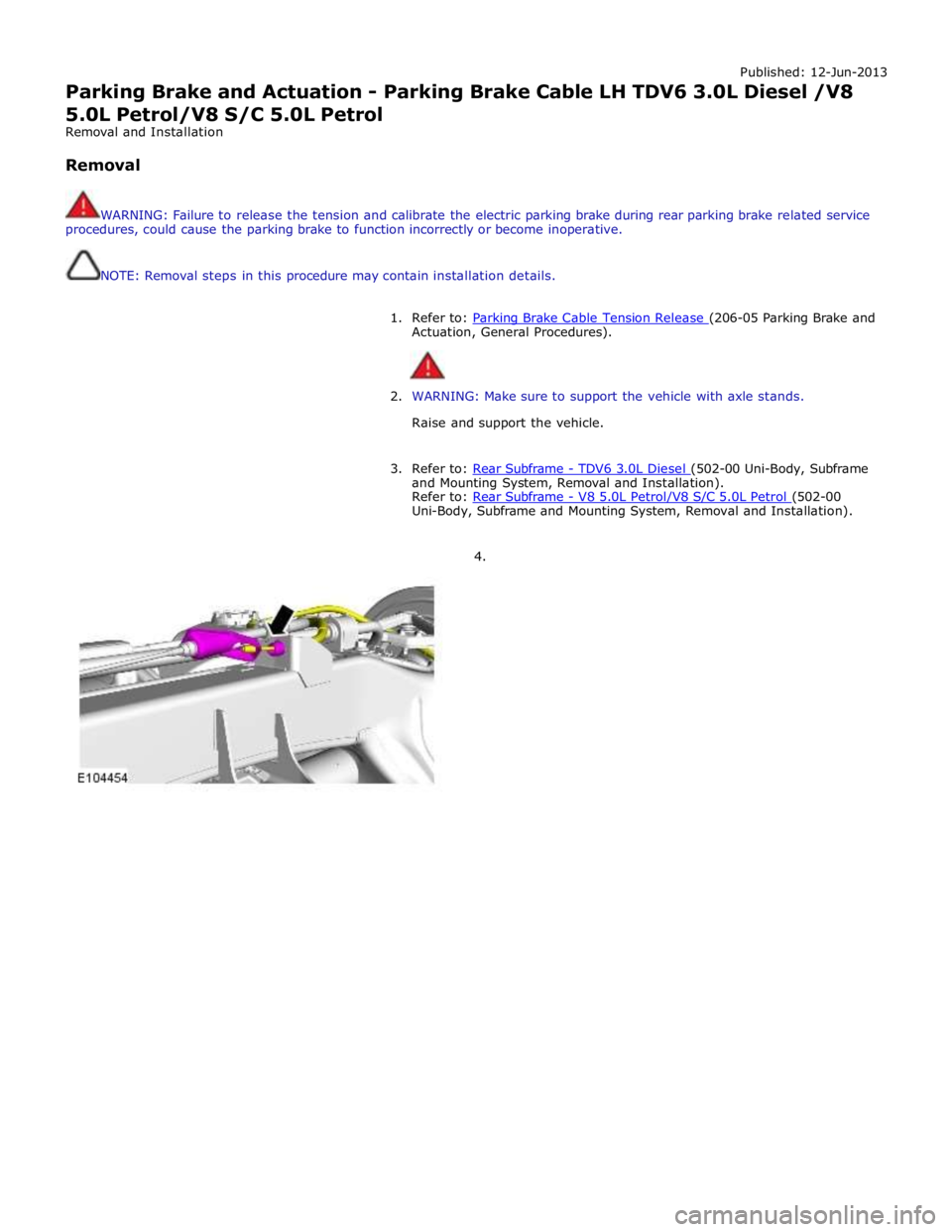
4.
Page 660 of 3039
Published: 12-Jun-2013
Parking Brake and Actuation - Parking Brake Cable RH TDV6 3.0L Diesel /V8 5.0L Petrol/V8 S/C 5.0L Petrol
Removal and Installation
Removal
WARNING: Failure to release the tension and calibrate the electric parking brake during rear parking brake related service
procedures, could cause the parking brake to function incorrectly or become inoperative.
NOTE: Removal steps in this procedure may contain installation details.
1. Refer to: Parking Brake Cable Tension Release (206-05 Parking Brake and Actuation, General Procedures).
2. WARNING: Make sure to support the vehicle with axle stands.
Raise and support the vehicle.
3. Refer to: Rear Subframe - TDV6 3.0L Diesel (502-00 Uni-Body, Subframe and Mounting System, Removal and Installation).
Refer to: Rear Subframe - V8 5.0L Petrol/V8 S/C 5.0L Petrol (502-00 Uni-Body, Subframe and Mounting System, Removal and Installation).
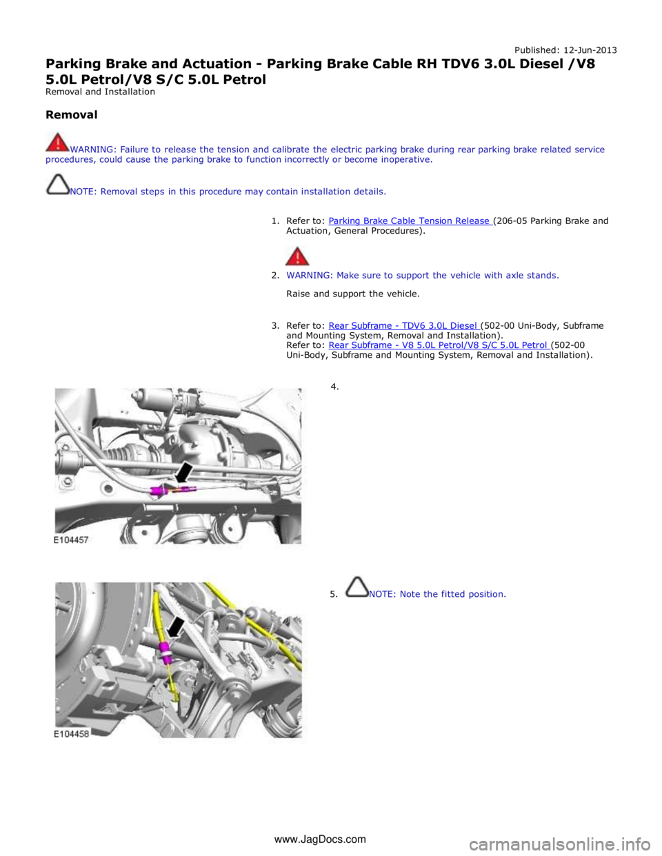
4.
5. NOTE: Note the fitted position. www.JagDocs.com
Page 845 of 3039
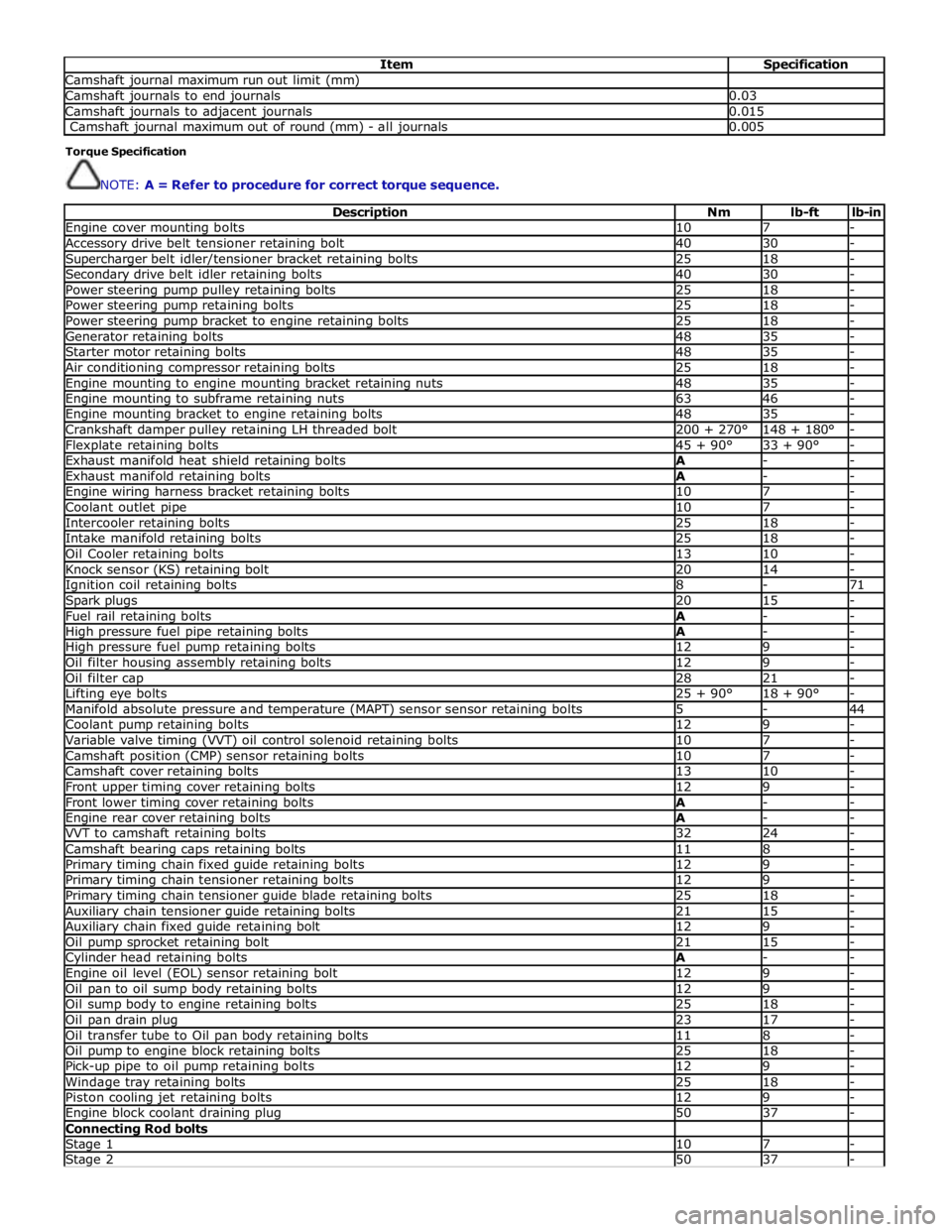
Item Specification Camshaft journal maximum run out limit (mm) Camshaft journals to end journals 0.03 Camshaft journals to adjacent journals 0.015 Camshaft journal maximum out of round (mm) - all journals 0.005 Torque Specification
NOTE: A = Refer to procedure for correct torque sequence.
Description Nm lb-ft lb-in Engine cover mounting bolts 10 7 - Accessory drive belt tensioner retaining bolt 40 30 - Supercharger belt idler/tensioner bracket retaining bolts 25 18 - Secondary drive belt idler retaining bolts 40 30 - Power steering pump pulley retaining bolts 25 18 - Power steering pump retaining bolts 25 18 - Power steering pump bracket to engine retaining bolts 25 18 - Generator retaining bolts 48 35 - Starter motor retaining bolts 48 35 - Air conditioning compressor retaining bolts 25 18 - Engine mounting to engine mounting bracket retaining nuts 48 35 - Engine mounting to subframe retaining nuts 63 46 - Engine mounting bracket to engine retaining bolts 48 35 - Crankshaft damper pulley retaining LH threaded bolt 200 + 270° 148 + 180° - Flexplate retaining bolts 45 + 90° 33 + 90° - Exhaust manifold heat shield retaining bolts A - - Exhaust manifold retaining bolts A - - Engine wiring harness bracket retaining bolts 10 7 - Coolant outlet pipe 10 7 - Intercooler retaining bolts 25 18 - Intake manifold retaining bolts 25 18 - Oil Cooler retaining bolts 13 10 - Knock sensor (KS) retaining bolt 20 14 - Ignition coil retaining bolts 8 - 71 Spark plugs 20 15 - Fuel rail retaining bolts A - - High pressure fuel pipe retaining bolts A - - High pressure fuel pump retaining bolts 12 9 - Oil filter housing assembly retaining bolts 12 9 - Oil filter cap 28 21 - Lifting eye bolts 25 + 90° 18 + 90° - Manifold absolute pressure and temperature (MAPT) sensor sensor retaining bolts 5 - 44 Coolant pump retaining bolts 12 9 - Variable valve timing (VVT) oil control solenoid retaining bolts 10 7 - Camshaft position (CMP) sensor retaining bolts 10 7 - Camshaft cover retaining bolts 13 10 - Front upper timing cover retaining bolts 12 9 - Front lower timing cover retaining bolts A - - Engine rear cover retaining bolts A - - VVT to camshaft retaining bolts 32 24 - Camshaft bearing caps retaining bolts 11 8 - Primary timing chain fixed guide retaining bolts 12 9 - Primary timing chain tensioner retaining bolts 12 9 - Primary timing chain tensioner guide blade retaining bolts 25 18 - Auxiliary chain tensioner guide retaining bolts 21 15 - Auxiliary chain fixed guide retaining bolt 12 9 - Oil pump sprocket retaining bolt 21 15 - Cylinder head retaining bolts A - - Engine oil level (EOL) sensor retaining bolt 12 9 - Oil pan to oil sump body retaining bolts 12 9 - Oil sump body to engine retaining bolts 25 18 - Oil pan drain plug 23 17 - Oil transfer tube to Oil pan body retaining bolts 11 8 - Oil pump to engine block retaining bolts 25 18 - Pick-up pipe to oil pump retaining bolts 12 9 - Windage tray retaining bolts 25 18 - Piston cooling jet retaining bolts 12 9 - Engine block coolant draining plug 50 37 - Connecting Rod bolts Stage 1 10 7 - Stage 2 50 37 -
Page 1116 of 3039
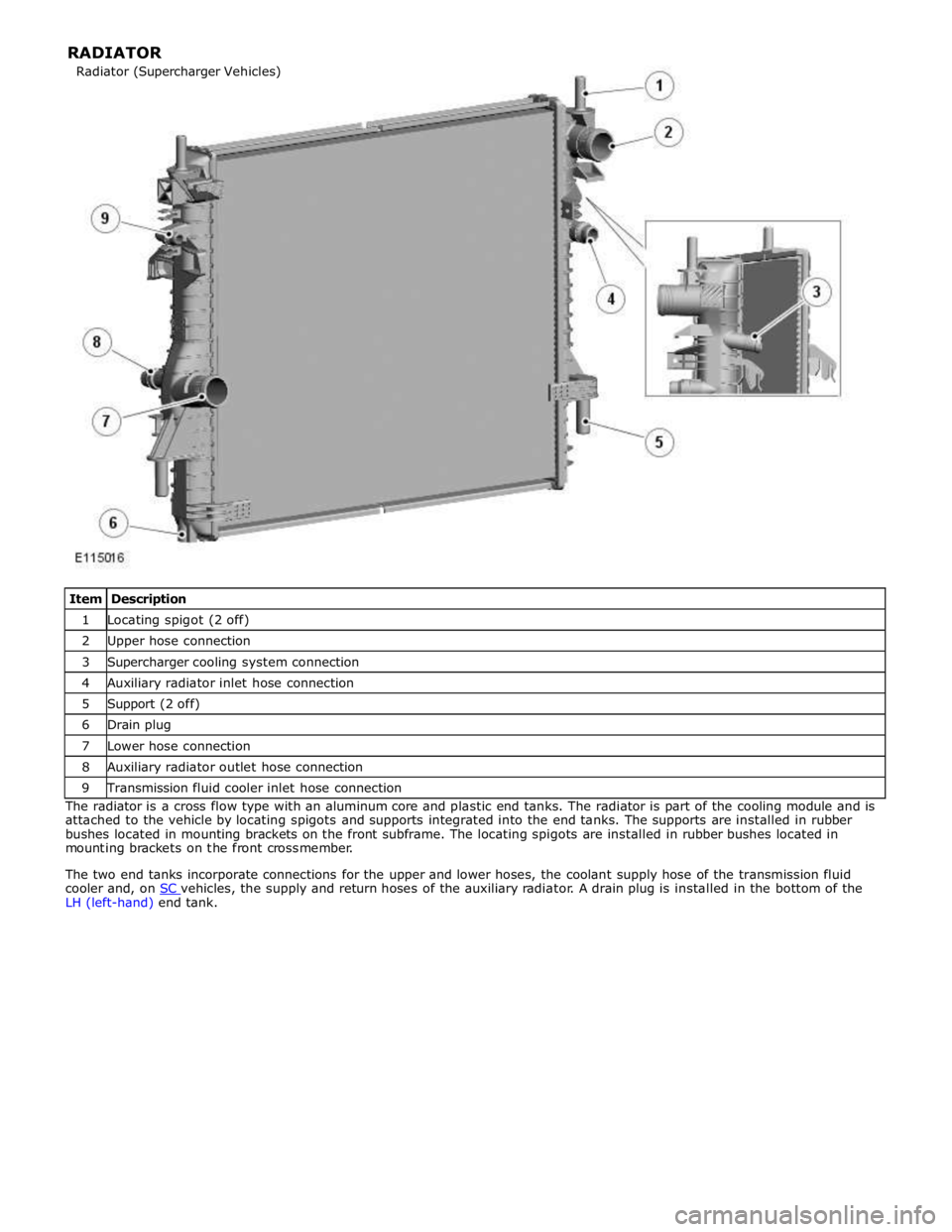
1 Locating spigot (2 off) 2 Upper hose connection 3 Supercharger cooling system connection 4 Auxiliary radiator inlet hose connection 5 Support (2 off) 6 Drain plug 7 Lower hose connection 8 Auxiliary radiator outlet hose connection 9 Transmission fluid cooler inlet hose connection The radiator is a cross flow type with an aluminum core and plastic end tanks. The radiator is part of the cooling module and is
attached to the vehicle by locating spigots and supports integrated into the end tanks. The supports are installed in rubber
bushes located in mounting brackets on the front subframe. The locating spigots are installed in rubber bushes located in
mounting brackets on the front crossmember.
The two end tanks incorporate connections for the upper and lower hoses, the coolant supply hose of the transmission fluid
cooler and, on SC vehicles, the supply and return hoses of the auxiliary radiator. A drain plug is installed in the bottom of the LH (left-hand) end tank. Radiator (Supercharger Vehicles) RADIATOR
Page 1519 of 3039

Published: 11-May-2011
Transmission/Transaxle Cooling - TDV6 3.0L Diesel /V8 5.0L Petrol/V8 S/C 5.0L Petrol - Transmission Cooling - Overview
Description and Operation
OVERVIEW
Transmission cooling is provided by a transmission fluid cooler, which transfers heat from the transmission to the engine
cooling system. The transmission fluid cooler is attached to a mounting bracket on the front subframe, in the front left corner
of the engine compartment.
Two hose and pipe assemblies connect the transmission fluid cooler to the automatic transmission. Two engine coolant hose
connections are incorporated into the top of the transmission fluid cooler for the supply and return of coolant from the engine
cooling system. For additional information, refer to 303-03D Engine Cooling.
Page 2744 of 3039
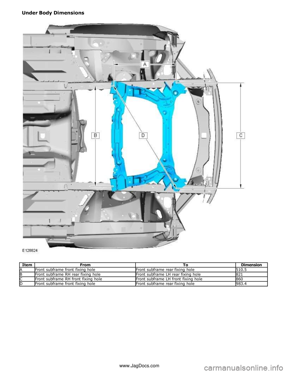
A Front subframe front fixing hole Front subframe rear fixing hole 510.5 B Front subframe RH rear fixing hole Front subframe LH rear fixing hole 821 C Front subframe RH front fixing hole Front subframe LH front fixing hole 860 D Front subframe front fixing hole Front subframe rear fixing hole 983.4 www.JagDocs.com
Page 2745 of 3039
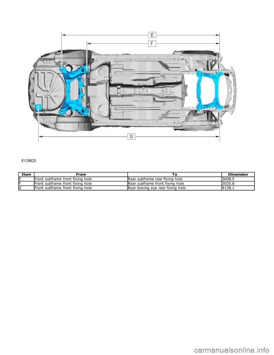
E Front subframe front fixing hole Rear subframe rear fixing hole 3608.5 F Front subframe front fixing hole Rear subframe front fixing hole 3035.8 G Front subframe front fixing hole Rear towing eye rear fixing hole 4138.1
Page 2746 of 3039
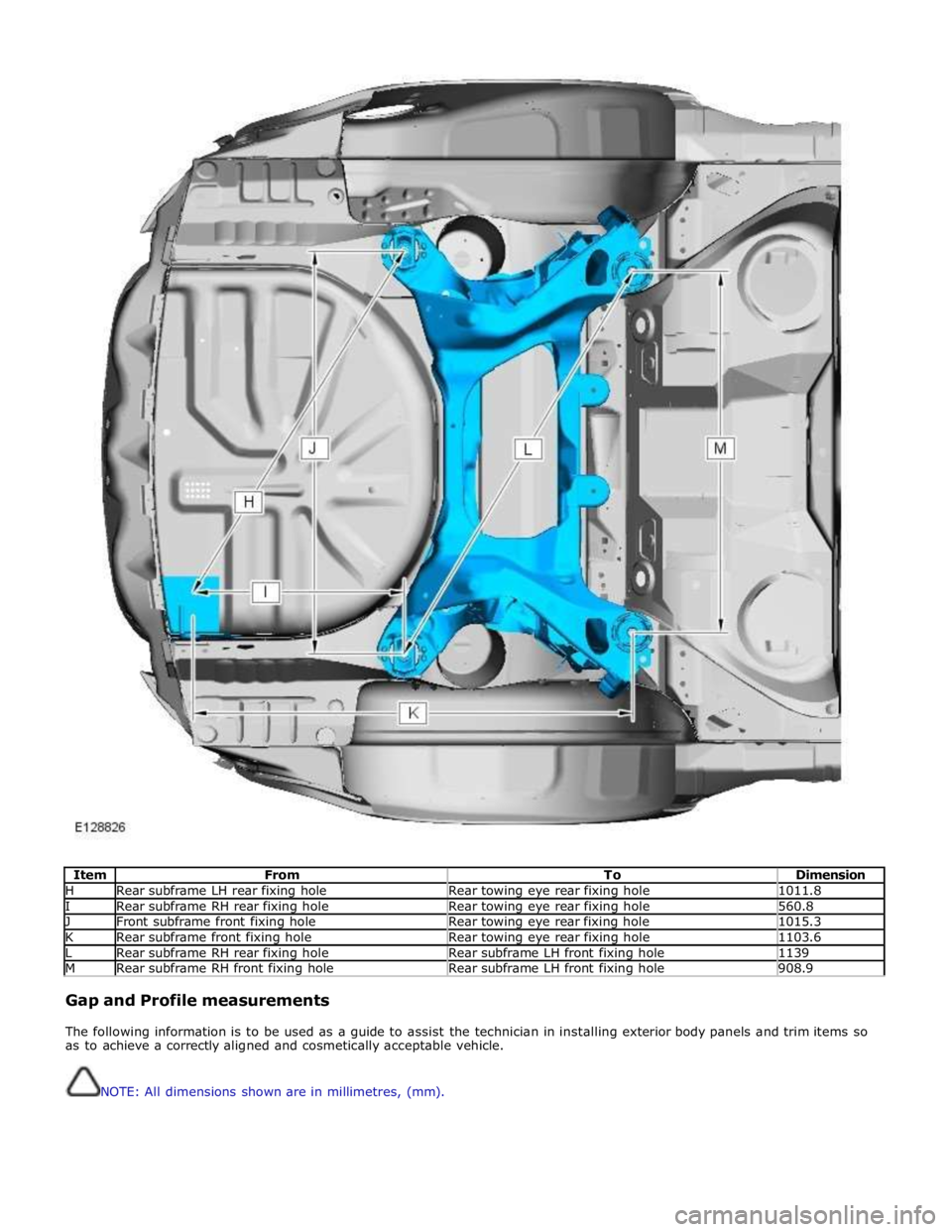
Item From To Dimension H Rear subframe LH rear fixing hole Rear towing eye rear fixing hole 1011.8 I Rear subframe RH rear fixing hole Rear towing eye rear fixing hole 560.8 J Front subframe front fixing hole Rear towing eye rear fixing hole 1015.3 K Rear subframe front fixing hole Rear towing eye rear fixing hole 1103.6 L Rear subframe RH rear fixing hole Rear subframe LH front fixing hole 1139 M Rear subframe RH front fixing hole Rear subframe LH front fixing hole 908.9
Gap and Profile measurements
The following information is to be used as a guide to assist the technician in installing exterior body panels and trim items so
as to achieve a correctly aligned and cosmetically acceptable vehicle.
NOTE: All dimensions shown are in millimetres, (mm).
Page 2784 of 3039
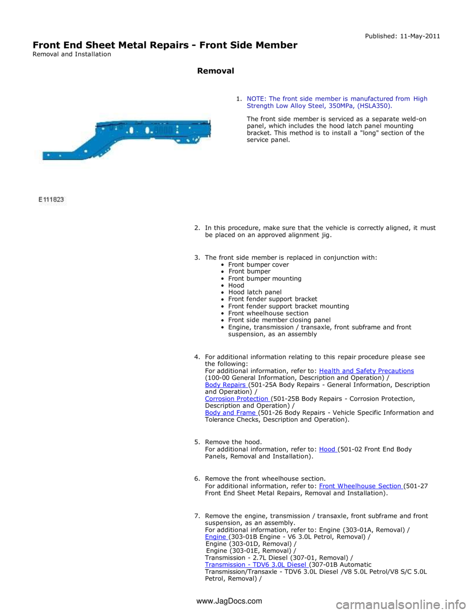
Front End Sheet Metal Repairs - Front Side Member
Removal and Installation
Removal Published: 11-May-2011
1. NOTE: The front side member is manufactured from High
Strength Low Alloy Steel, 350MPa, (HSLA350).
The front side member is serviced as a separate weld-on
panel, which includes the hood latch panel mounting
bracket. This method is to install a "long" section of the
service panel.
2. In this procedure, make sure that the vehicle is correctly aligned, it must
be placed on an approved alignment jig.
3. The front side member is replaced in conjunction with:
Front bumper cover
Front bumper
Front bumper mounting
Hood
Hood latch panel
Front fender support bracket
Front fender support bracket mounting
Front wheelhouse section
Front side member closing panel
Engine, transmission / transaxle, front subframe and front
suspension, as an assembly
4. For additional information relating to this repair procedure please see
the following:
For additional information, refer to: Health and Safety Precautions (100-00 General Information, Description and Operation) /
Body Repairs (501-25A Body Repairs - General Information, Description and Operation) /
Corrosion Protection (501-25B Body Repairs - Corrosion Protection, Description and Operation) /
Body and Frame (501-26 Body Repairs - Vehicle Specific Information and Tolerance Checks, Description and Operation).
5. Remove the hood.
For additional information, refer to: Hood (501-02 Front End Body Panels, Removal and Installation).
6. Remove the front wheelhouse section.
For additional information, refer to: Front Wheelhouse Section (501-27 Front End Sheet Metal Repairs, Removal and Installation).
7. Remove the engine, transmission / transaxle, front subframe and front
suspension, as an assembly.
For additional information, refer to: Engine (303-01A, Removal) /
Engine (303-01B Engine - V6 3.0L Petrol, Removal) / Engine (303-01D, Removal) /
Engine (303-01E, Removal) /
Transmission - 2.7L Diesel (307-01, Removal) /
Transmission - TDV6 3.0L Diesel (307-01B Automatic Transmission/Transaxle - TDV6 3.0L Diesel /V8 5.0L Petrol/V8 S/C 5.0L
Petrol, Removal) / www.JagDocs.com
Page 2785 of 3039
Transmission (307-01A Automatic Transmission/Transaxle - V6 3.0L Petrol, Removal) /
Transmission - 4.2L (307-01, Removal) /
Transmission - V8 5.0L Petrol/V8 S/C 5.0L Petrol (307-01B Automatic Transmission/Transaxle - TDV6 3.0L Diesel /V8 5.0L Petrol/V8 S/C 5.0L
Petrol, Removal) /
Front Shock Absorber (204-01 Front Suspension, Removal and Installation) /
Front Subframe - 2.7L Diesel (502-00, Removal and Installation) /
Front Subframe - V6 3.0L Petrol (502-00 Uni-Body, Subframe and Mounting System, Removal and Installation) /
Front Subframe - 4.2L, Vehicles Without: Supercharger (502-00, Removal
and Installation) /
Front Subframe - 4.2L, Vehicles With: Supercharger (502-00, Removal
and Installation).
8. Remove the pedestrian protection hood actuator.
For additional information, refer to: Pedestrian Protection Hood Actuator LH (501-20C Pedestrian Protection System, Removal and Installation) / Pedestrian Protection Hood Actuator RH (501-20C Pedestrian Protection System, Removal and Installation).
9. If the drivers side front side member and suspension top mount is to be
repaired, remove the brake master cylinder and reservoir.
For additional information, refer to: Brake Master Cylinder (206-06 Hydraulic Brake Actuation, Removal and Installation) /
Brake Fluid Reservoir (206-06 Hydraulic Brake Actuation, Removal and Installation).
10. If the left-hand front side member and suspension top mount assembly
is to be repaired, remove the fuel supply and return lines.
11. Release and position the front side member wiring harness to one side.
12. Remove any remaining miscellaneous components from the repair area.
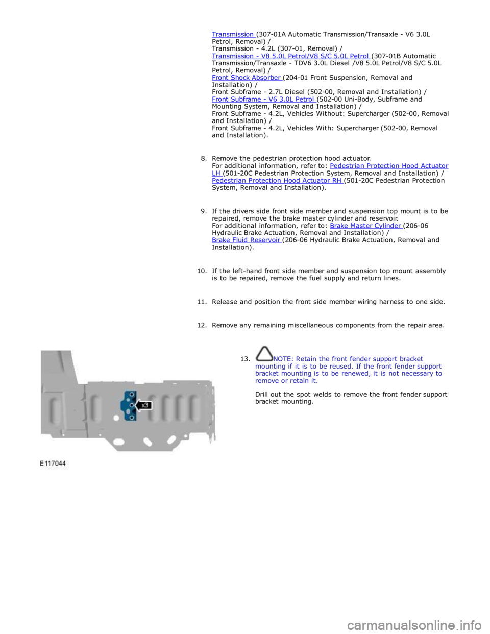
13. NOTE: Retain the front fender support bracket
mounting if it is to be reused. If the front fender support
bracket mounting is to be renewed, it is not necessary to
remove or retain it.
Drill out the spot welds to remove the front fender support
bracket mounting.