brake sensor JAGUAR XFR 2010 1.G User Guide
[x] Cancel search | Manufacturer: JAGUAR, Model Year: 2010, Model line: XFR, Model: JAGUAR XFR 2010 1.GPages: 3039, PDF Size: 58.49 MB
Page 239 of 3039

DTC Description Possible Causes Action speed control sensor, check and install a new sensor
as required, refer to the new module/component
installation note at the top of the DTC Index C1A67-96 Forward Looking Sensor
- Component internal
Failure
Internal hardware failure
Suspect the speed control sensor. Check and install a
new sensor as required, refer to the new
module/component installation note at the top of
the DTC Index C1A67-97 Forward Looking Sensor
- Component or system
operation obstructed or
blocked
Sensor reduced visibility
Check for blockage in front of radar. Note: This DTC
will be cleared automatically when environmental
conditions allow C1A67-98 Forward Looking Sensor
- Component or system
over temperature
Speed control sensor
internal temperature
exceeded threshold
Allow system to cool. Note: This DTC will be cleared
automatically when environmental conditions allow P174E-81
Output Shaft
Speed/ABS Wheel
Speed Correlation -
Invalid serial data
received
Follow speed is
mis-calculated to too
high a value
Clear DTC and re-test U0001-88
High Speed CAN
Communication Bus -
Bus off
Vehicle CAN Bus off
condition
Carry out any pinpoint tests associated with this
DTC using the manufacturer approved diagnostic
system. Carry out CAN network integrity tests using
the manufacturer approved diagnostic system U0100-00
Lost Communications
With ECM/PCM "A" - No
sub type information
ECM missing message
Carry out any pinpoint tests associated with this
DTC using the manufacturer approved diagnostic
system. Check ECM for related DTCs and refer to the
relevant DTC Index U0101-00
Lost Communications
With TCM - No sub
type information
TCM missing message
Carry out any pinpoint tests associated with this
DTC using the manufacturer approved diagnostic
system. Check TCM for related DTCs and refer to the
relevant DTC Index U0103-00
Lost Communication
With Gear Shift Control
Module A - No sub type
information
No sub type information
Refer to the electrical circuit diagrams and check the
power and ground connections to the Transmission
Shift Module. Using the manufacturer approved
diagnostic system, complete a CAN network integrity
test. Refer to the electrical circuit diagrams and
check the CAN network between the Transmission
Shift Module and Speed Control Module U0103-87
Lost Communication
With Gear Shift Module
- Missing Message
Transmission shift
module missing message
Carry out any pinpoint tests associated with this
DTC using the manufacturer approved diagnostic
system. Check transmission shift module for related
DTCs and refer to the relevant DTC Index U0121-00
Lost Communication
With Anti-lock Brake
System (ABS) Control
Module - No sub type
information
ABS missing message
Carry out any pinpoint tests associated with this
DTC using the manufacturer approved diagnostic
system. Check ABS for related DTCs and refer to the
relevant DTC Index U0128-00
Lost Communications
With Park Brake Module
- No sub type
information
Parking brake missing
message
Carry out any pinpoint tests associated with this
DTC using the manufacturer approved diagnostic
system. Check parking brake module for related
DTCs and refer to the relevant DTC Index U0155-00
Lost Communications
With Instrument Panel
Cluster (IPC) Control
Module - No sub type
information
Instrument cluster
missing message
Carry out any pinpoint tests associated with this
DTC using the manufacturer approved diagnostic
system. Check instrument cluster for related DTCs
and refer to the relevant DTC Index
Page 267 of 3039
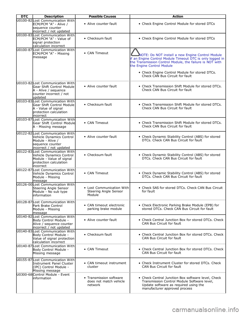
DTC Description Possible Causes Action U0100-82
Lost Communication With
ECM/PCM "A" - Alive /
sequence counter
incorrect / not updated
Alive counter fault
Check Engine Control Module for stored DTCs U0100-83
Lost Communication With
ECM/PCM "A" - Value of
signal protection
calculation incorrect
Checksum fault
Check Engine Control Module for stored DTCs U0100-87
Lost Communication With
ECM/PCM "A" - Missing
message
CAN Timeout
NOTE: Do NOT install a new Engine Control Module
if an Engine Control Module Timeout DTC is only logged in
the Transmission Control Module, the failure is NOT with
the Engine Control Module
Check Engine Control Module for stored DTCs.
Check CAN Bus Circuit for fault U0103-82
Lost Communication With
Gear Shift Control Module
A - Alive / sequence
counter incorrect / not updated
Alive counter fault
Check Transmission Shift Module for stored DTCs.
Check CAN Bus Circuit for fault U0103-83
Lost Communication With
Gear Shift Control Module
A - Value of signal
protection calculation
incorrect
Checksum fault
Check Transmission Shift Module for stored DTCs.
Check CAN Bus Circuit for fault U0103-87
Lost Communication With
Gear Shift Control Module
A - Missing message
CAN Timeout
Check Transmission Shift Module for stored DTCs.
Check CAN Bus Circuit for fault U0122-82
Lost Communication With
Vehicle Dynamics Control
Module - Alive /
sequence counter
incorrect / not updated
Alive counter fault
Check Dynamic Stability Control (ABS) for stored
DTCs. Check CAN Bus Circuit for fault U0122-83
Lost Communication With
Vehicle Dynamics Control
Module - Value of signal
protection calculation
incorrect
Checksum fault
Check Dynamic Stability Control (ABS) for stored
DTCs. Check CAN Bus Circuit for fault U0122-87
Lost Communication With
Vehicle Dynamics Control
Module - Missing message
CAN Timeout
Check Dynamic Stability Control (ABS) for stored
DTCs. Check CAN Bus Circuit for fault U0126-00
Lost Communication With
Steering Angle Sensor
Module - No sub type
information
Lost Communication With
Steering Angle Sensor
Module
Check SAS for stored DTCs. Check CAN Bus Circuit
for fault U0128-87
Lost Communication With
Park Brake Control
Module - Missing message
CAN timeout electronic
parking brake module
Check Electronic Parking Brake Module (EPB) for
stored DTCs. Check CAN Bus Circuit for fault U0140-82
Lost Communication With
Body Control Module -
Alive / sequence counter
incorrect / not updated
Alive counter fault
Check Central Junction Box for stored DTCs. Check
CAN Bus Circuit for fault U0140-83
Lost Communication With
Body Control Module -
Value of signal protection
calculation incorrect
Checksum fault
Check Central Junction Box for stored DTCs. Check
CAN Bus Circuit for fault U0140-87
Lost Communication With
Body Control Module -
Missing message
CAN Timeout
Check Central Junction Box for stored DTCs. Check
CAN Bus Circuit for fault U0155-87
Lost Communication With
Instrument Panel Cluster
(IPC) Control Module - Missing message
CAN timeout instrument
cluster
Check Instrument Cluster for stored DTCs. Check
CAN Bus Circuit for fault U0300-68
Control Module - Event
information
Transmission software
does not match vehicle
network
Check Central Junction Box software level, Check
Transmission Control Module Software level,
Update software as required using the
manufacturer approved process
Page 332 of 3039

Upper Control Arm
The forged-aluminum upper control arm is a wishbone design and connects to the vehicle body through two plain bushes, and
links to the swan neck wheel knuckle by an integral ball joint. The upper control arm is inclined to provide anti-dive
characteristics under heavy braking, while also controlling geometry for vehicle straight-line stability.
Lower Control Arm
The forged aluminum lower control arms are of the wishbone design; the arms separate to allow for optimum bush tuning:
The rear lateral control arm is fitted with a bush at its inner end which locates between brackets on the subframe. The
arm is secured with an eccentric bolt which provides the adjustment of the suspension camber geometry. The outer end
of the control arm has a tapered hole which locates on a ball joint fitted to the wheel knuckle. An integral clevis bracket
on the forward face of the lateral control arm allows for the attachment of the forward control arm. A bush is fitted
below the clevis bracket to provide for the attachment of the stabilizer bar link. A cross-axis joint is fitted to a
cross-hole in the control arm to provide the location for the clevis attachment of the spring and damper assembly.
The forward control arm is fitted with a fluid-block rubber bush at its inner end which locates between brackets on the
subframe. The arm is secured with an eccentric bolt which provides adjustment of the castor and camber geometry. The
outer end of the control arm is fitted with a cross-axis joint and locates in the integral clevis bracket on the lateral
control arm.
Wheel Knuckle
The cast aluminum wheel knuckle is a swan neck design and attaches to the upper control arm and lower lateral control arm.
The lower lateral control arm locates on a non serviceable ball-joint integral with the wheel knuckle. The lower boss on the
rear of the knuckle provides for the attachment of the steering gear tie-rod ball joint.
The wheel knuckle also provides the mounting locations for the:
wheel hub and bearing assembly
the wheel speed sensor (integral to the wheel hub and bearing assembly)
brake caliper and disc shield.
Stabilizer Bar
The stabilizer bar is attached to the front of the subframe with bushes and mounting brackets. The pressed steel mounting
brackets locate over the bushes and are attached to the cross member with bolts screwed into threaded locations in the
subframe. The stabilizer bar has crimped, 'anti-shuffle' collars pressed in position on the inside edges of the bushes. The
collars prevent sideways movement of the stabilizer bar.
The stabilizer bar is manufactured from 32mm diameter tubular steel on supercharged models and 31mm diameter tubular
steel on diesel and normally aspirated models and has been designed to provide particular characteristics in maintaining roll
rates, specifically in primary ride comfort.
Each end of the stabilizer bar curves rearwards to attach to a ball joint on a stabilizer link. Each stabilizer link is secured to a
bush in the lower lateral arm with a bolt and locknut. The links allow the stabilizer bar to move with the wheel travel providing
maximum effectiveness.
The only difference between the front stabilizer bars, in addition to the diameter, is in the shape to accommodate engine
variant:
a slightly curved bar, between bush centers, for V6 diesel (31 mm dia) and V8 gasoline supercharged (32 mm dia),
a straight bar, between bush centers, for V6 and V8 normally aspirated gasoline engines (31 mm dia).
Spring and Damper Assembly
The spring and damper assemblies are located between the lower lateral arm and the front suspension housing in the inner
wing. Dependant on vehicle model there are three types of coil spring and damper available:
a standard oil passive damper (All models except supercharged),
an adaptive damper, also known as Computer Active Technology Suspension (CATS) on 4.2L supercharged vehicles up to
2010MY, For additional information refer to Vehicle Dynamic Suspension 4.2L.
a continuously variable adaptive damper, also known as Adaptive Dynamics System on 5.0L supercharged vehicles from
2010MY. For additional information refer to Vehicle Dynamic Suspension 5.0L.
The dampers are a monotube design with a spring seat secured by a circlip onto the damper tube. The damper's lower
spherical joint is an integral part of the lateral lower control-arm, and the damper takes the form of a clevis-end, which
straddles the spherical joint.
The damper piston is connected to a damper rod which is sealed at its exit point from the damper body. The threaded outer
end of the damper rod locates through a hole in the top mount. A self locking nut secures the top mount to the damper rod.
The damper rod on the adaptive damper has an electrical connector on the outer end of the damper rod.
Supercharged 4.2L vehicles up to 2010MY: The adaptive damper functions by restricting the flow of hydraulic fluid through
internal galleries in the damper's piston. The adaptive damper has a solenoid operated valve, which when switched allows a
greater flow of hydraulic fluid through the damper's piston. This provides a softer damping characteristic from the damper. The
adaptive damper defaults to a firmer setting when not activated. The solenoid is computer controlled and can switch between
soft and hard damping settings depending on road wheel inputs and vehicle speed.
Supercharged 5.0L vehicles from 2010MY: The variable damper functions by adjustment of a solenoid operated variable orifice,
which opens up an alternative path for oil flow within the damper. When de-energized the bypass is closed and all the oil flows
Page 395 of 3039

the aluminum wheel knuckle via an integral ball-joint.
Lower Control Arm
The aluminum lower arm locates to the subframe via one cross-axis joint and one plain rubber bush, and to the wheel knuckle
via a second plain rubber bush.
The rear of the control arm has mounting points for the damper and the stabilizer link.
Toe-Link
The toe-link is located between the wheel knuckle and brackets on the subframe.
The toe-link comprises an inner rod with integral axial ball joint. The inner ball joint has a threaded spigot which locates in a
bracket on the subframe and is secured with a locknut. The rod has an internal thread which accepts the outer rod.
The outer rod has a cross-axis joint at its outer end which is located in a clevis on the wheel knuckle, and is secured with a
bolt and locknut.
The length of the toe-link can be adjusted by rotating the inner rod. This allows for adjustment of the toe angle for the rear
wheel. Once set the inner rod can be locked in position by tightening a locknut on the outer rod against the inner rod.
Wheel Knuckle
The cast aluminum wheel knuckle attaches to:
the upper control arm via a ball-joint located in the arm,
the lower control arm via a plain rubber bush located in the arm,
the toe-link via a cross-axis joint located in the toe link.
The wheel knuckle also provides the mounting locations for the:
wheel hub assembly,
wheel bearing,
wheel speed sensor,
brake caliper,
and disc shield.
Stabilizer Bar
The solid construction stabilizer bar and bushes have been designed to provide particular characteristics in maintaining roll
rates, specifically in primary ride comfort. There are six derivatives of rear stabilizer bar, with different diameters, to support
the various powertrains:
V6 gasoline - 12.7 mm solid bar
V8 4.2L and 5.0L gasoline - 13.6 mm solid bar
V6 2.7L diesel -14.5 mm solid bar
V6 3.0L diesel - 14.5 mm solid bar
V6 3.0L diesel with Adaptive Damping – 16mm tubular
V8 4.2L gasoline supercharged – 16mm tubular
V8 5.0L gasoline supercharged
- SV8 - 17mm tubular
- XFR - 18mm tubular
The stabilizer bar is attached to the top of the subframe with two bushes and mounting brackets. The stabilizer bar has
crimped, 'anti-shuffle' collars pressed in position on the inside edges of the bushes. The collars prevent sideways movement of
the stabilizer bar.
Each end of the stabilizer bar curves rearward to attach to a ball joint on each stabilizer link. Each link is attached via a
second ball joint to a cast bracket on the lower control arm. The links allow the stabilizer bar to move with the wheel travel
providing maximum effectiveness.
Spring and Damper Assembly
The spring and damper assembly are attached to cast brackets on the lower control arms and to the vehicle body by four studs
secured by locking nuts. Dependant on vehicle model there are three types of coil spring and damper available:
a standard oil passive damper (All models except supercharged),
an adaptive damper, also known as Computer Active Technology Suspension (CATS) on 4.2L supercharged vehicles up to
2010MY, For additional information refer to Vehicle Dynamic Suspension 4.2L.
a continuously variable adaptive damper, also known as Adaptive Dynamics System on 5.0L supercharged vehicles from
2010MY. For additional information refer to Vehicle Dynamic Suspension 5.0L.
The dampers are a monotube design with a spring located by a circlip onto the damper tube. The lower end of the damper has
a spherical joint which locates in the lower control arm and is secured with a bolt.
The damper piston is connected to a damper rod which is sealed at its exit point from the damper body. The threaded outer
end of the damper rod locates through a hole in the top mount. A self locking nut secures the top mount to the damper rod.
The damper rod on the adaptive damper has an electrical connector on the outer end of the damper rod. www.JagDocs.com
Page 413 of 3039
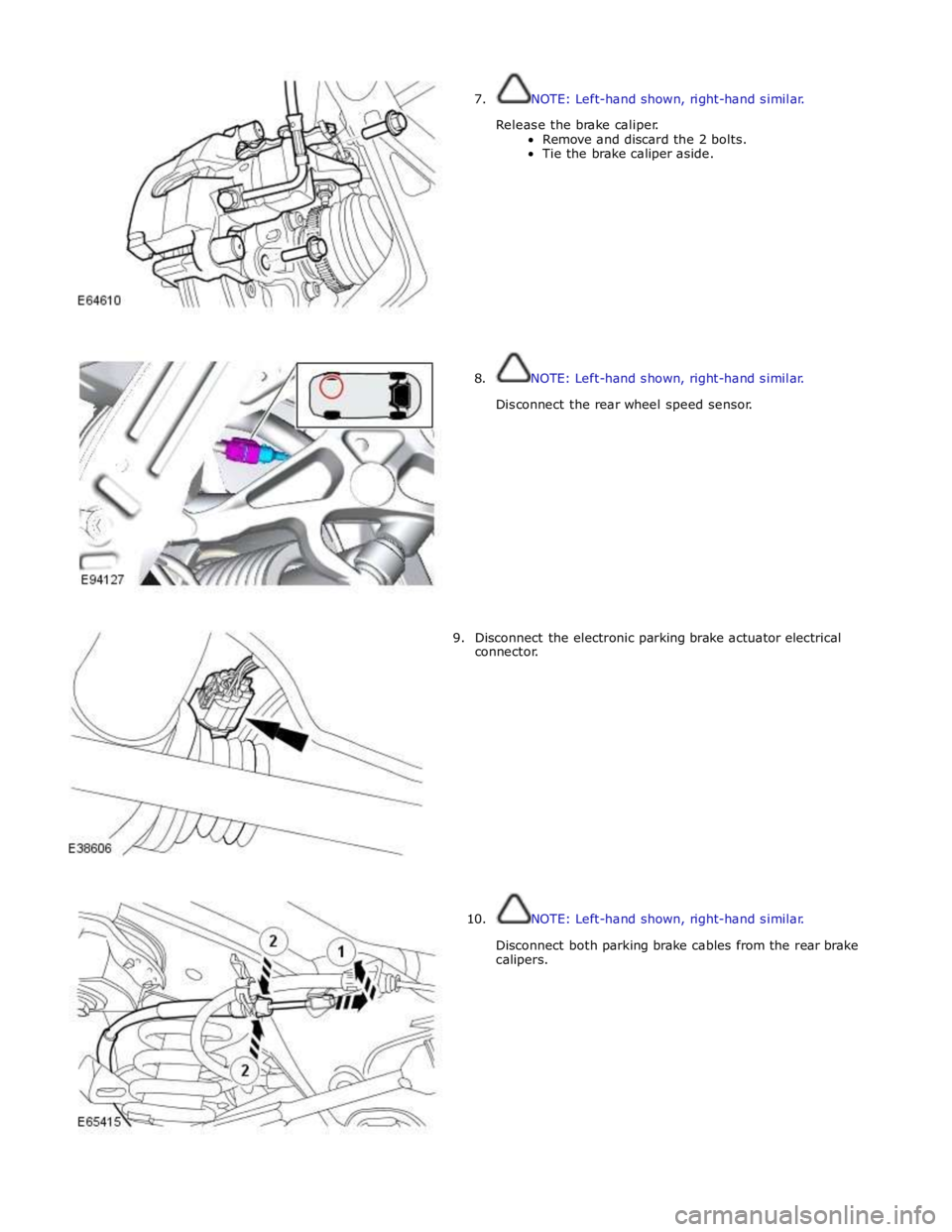
7. NOTE: Left-hand shown, right-hand similar.
Release the brake caliper.
Remove and discard the 2 bolts.
Tie the brake caliper aside.
8. NOTE: Left-hand shown, right-hand similar.
Disconnect the rear wheel speed sensor.
9. Disconnect the electronic parking brake actuator electrical
connector.
10. NOTE: Left-hand shown, right-hand similar.
Disconnect both parking brake cables from the rear brake
calipers.
Page 483 of 3039
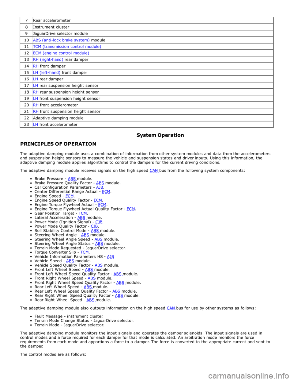
7 Rear accelerometer 8 Instrument cluster 9 JaguarDrive selector module 10 ABS (anti-lock brake system) module 11 TCM (transmission control module) 12 ECM (engine control module) 13 RH (right-hand) rear damper 14 RH front damper 15 LH (left-hand) front damper 16 LH rear damper 17 LH rear suspension height sensor 18 RH rear suspension height sensor 19 LH front suspension height sensor 20 RH front accelerometer 21 RH front suspension height sensor 22 Adaptive damping module 23 LH front accelerometer
PRINCIPLES OF OPERATION System Operation
The adaptive damping module uses a combination of information from other system modules and data from the accelerometers
and suspension height sensors to measure the vehicle and suspension states and driver inputs. Using this information, the
adaptive damping module applies algorithms to control the dampers for the current driving conditions.
The adaptive damping module receives signals on the high speed CAN bus from the following system components: Brake Pressure - ABS module. Brake Pressure Quality Factor - ABS module. Car Configuration Parameters - AJB. Center Differential Range Actual - ECM. Engine Speed - ECM. Engine Speed Quality Factor - ECM. Engine Torque Flywheel Actual - ECM. Engine Torque Flywheel Actual Quality Factor - ECM. Gear Position Target - TCM. Lateral Acceleration - ABS module. Power Mode (Ignition Signal) - CJB. Power Mode Quality Factor - CJB. Roll Stability Control Mode - ABS module. Steering Wheel Angle - ABS module. Steering Wheel Angle Speed - ABS module. Steering Wheel Angle Status - ABS module. Terrain Mode Requested - JaguarDrive selector.
Torque Converter Slip - TCM. Vehicle Information Parameters HS - AJB Vehicle Speed - ABS module. Vehicle Speed Quality Factor - ABS module. Front Left Wheel Speed - ABS module. Front Left Wheel Speed Quality Factor - ABS module. Front Right Wheel Speed - ABS module. Front Right Wheel Speed Quality Factor - ABS module. Rear Left Wheel Speed - ABS module. Rear Left Wheel Speed Quality Factor - ABS module. Rear Right Wheel Speed Quality Factor - ABS module. Rear Right Wheel Speed - ABS module. The adaptive damping module also outputs information on the high speed CAN bus for use by other systems as follows: Fault Message - instrument cluster.
Terrain Mode Change Status - JaguarDrive selector.
Terrain Mode - JaguarDrive selector.
The adaptive damping module monitors the input signals and operates the damper solenoids. The input signals are used in
control modes and a force required for each damper for that mode is calculated. An arbitration mode monitors the force
requirements from each mode and apportions a force to a damper. The force is converted to the appropriate current and sent to
the damper.
The control modes are as follows:
Page 532 of 3039

6 Oil temperature sensor 7 High speed CAN from suspension control module 8 CJB (central junction box)
System Operation
ELECTRONIC
DIFFERENTIAL
-
5.0L
SUPERCHARGER
VEHICLES
FROM
2010MY
The
multi-plate
clutch
prevents
excessive
differential
slip and
therefore
maximizes
the
traction
performance
of
the
vehicle.
This
is
fundamentally
different
from
'braked'
traction
control
systems,
which
can
only
counteract
differential
slip when it
occurs.
A
certain
amount
of
differential
slip is
required
to
allow
the
vehicle
to
turn
corners
and
to
remain
stable
under
control
of
the
ABS
(anti-lock
brake
system).
The
system
is
completely
automatic and
does
not
require
any
special
driver
input.
The
multi-plate
clutch
actively
controls
the
torque
flow
through
the
differential
and
optimizes
the
torque
distribution in
the
driveline.
The
clutch
biases
the
torque
from
the
differential
to
the
wheel
with the
higher
grip
and prevents
the
wheel
with the
lower
grip
from
spinning.
www.JagDocs.com
Page 583 of 3039
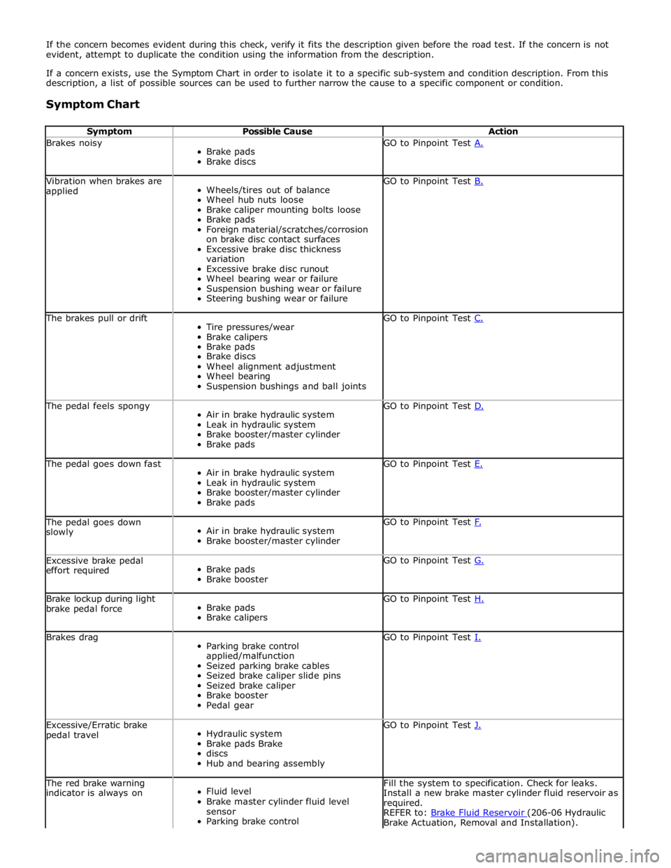
If the concern becomes evident during this check, verify it fits the description given before the road test. If the concern is not
evident, attempt to duplicate the condition using the information from the description.
If a concern exists, use the Symptom Chart in order to isolate it to a specific sub-system and condition description. From this
description, a list of possible sources can be used to further narrow the cause to a specific component or condition.
Symptom Chart
Symptom Possible Cause Action Brakes noisy
Brake pads
Brake discs GO to Pinpoint Test A. Vibration when brakes are
applied
Wheels/tires out of balance
Wheel hub nuts loose
Brake caliper mounting bolts loose
Brake pads
Foreign material/scratches/corrosion
on brake disc contact surfaces
Excessive brake disc thickness
variation
Excessive brake disc runout
Wheel bearing wear or failure
Suspension bushing wear or failure
Steering bushing wear or failure GO to Pinpoint Test B. The brakes pull or drift
Tire pressures/wear
Brake calipers
Brake pads
Brake discs
Wheel alignment adjustment
Wheel bearing
Suspension bushings and ball joints GO to Pinpoint Test C. The pedal feels spongy
Air in brake hydraulic system
Leak in hydraulic system
Brake booster/master cylinder
Brake pads GO to Pinpoint Test D. The pedal goes down fast
Air in brake hydraulic system
Leak in hydraulic system
Brake booster/master cylinder
Brake pads GO to Pinpoint Test E. The pedal goes down
slowly
Air in brake hydraulic system
Brake booster/master cylinder GO to Pinpoint Test F. Excessive brake pedal
effort required
Brake pads
Brake booster GO to Pinpoint Test G. Brake lockup during light
brake pedal force
Brake pads
Brake calipers GO to Pinpoint Test H. Brakes drag
Parking brake control
applied/malfunction
Seized parking brake cables
Seized brake caliper slide pins
Seized brake caliper
Brake booster
Pedal gear GO to Pinpoint Test I. Excessive/Erratic brake
pedal travel
Hydraulic system
Brake pads Brake
discs
Hub and bearing assembly GO to Pinpoint Test J. The red brake warning
indicator is always on
Fluid level
Brake master cylinder fluid level
sensor
Parking brake control Fill the system to specification. Check for leaks.
Install a new brake master cylinder fluid reservoir as
required.
REFER to: Brake Fluid Reservoir (206-06 Hydraulic Brake Actuation, Removal and Installation).
Page 590 of 3039
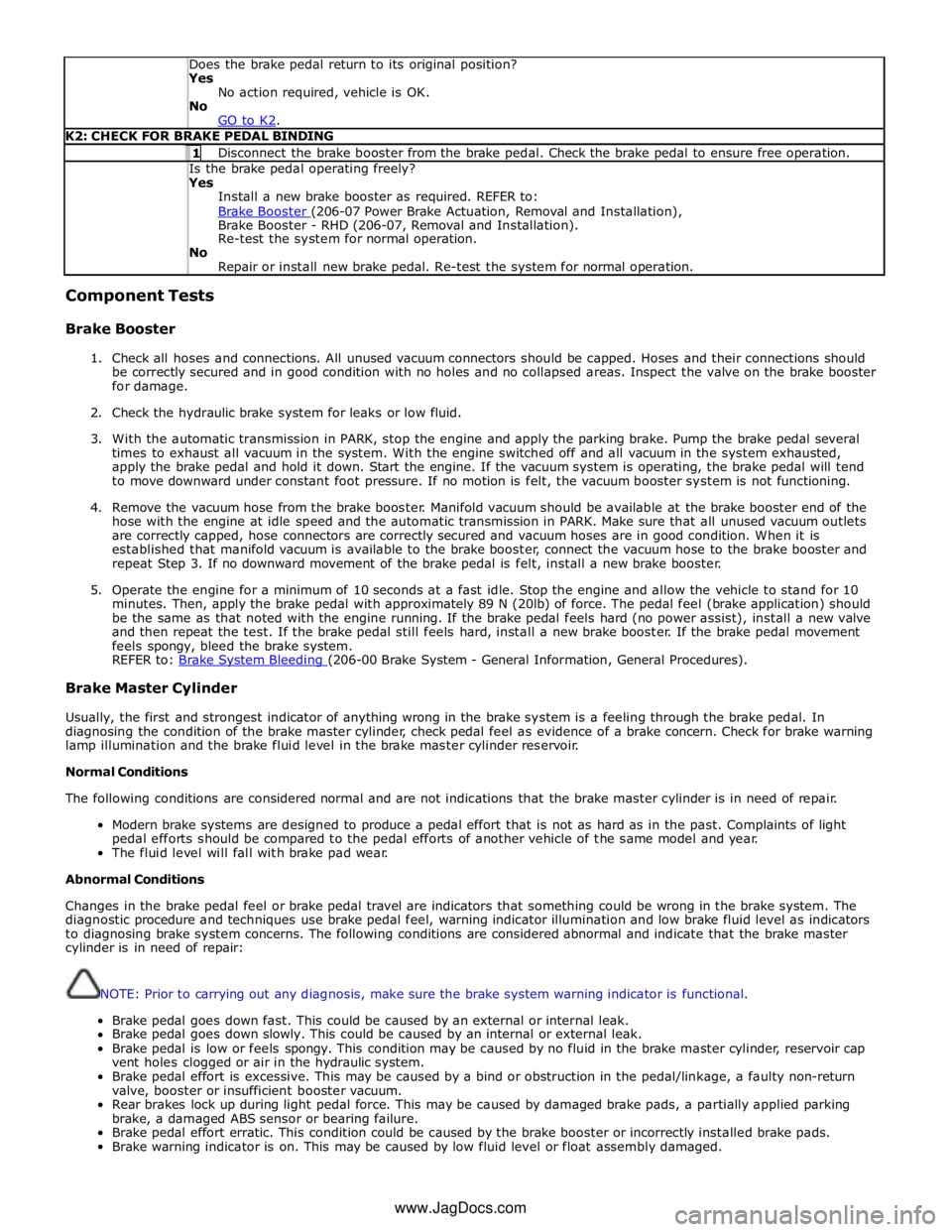
Does the brake pedal return to its original position? Yes
No action required, vehicle is OK.
No
GO to K2. K2: CHECK FOR BRAKE PEDAL BINDING 1 Disconnect the brake booster from the brake pedal. Check the brake pedal to ensure free operation. Is the brake pedal operating freely? Yes
Install a new brake booster as required. REFER to:
Brake Booster (206-07 Power Brake Actuation, Removal and Installation), Brake Booster - RHD (206-07, Removal and Installation).
Re-test the system for normal operation.
No
Repair or install new brake pedal. Re-test the system for normal operation. Component Tests
Brake Booster
1. Check all hoses and connections. All unused vacuum connectors should be capped. Hoses and their connections should
be correctly secured and in good condition with no holes and no collapsed areas. Inspect the valve on the brake booster
for damage.
2. Check the hydraulic brake system for leaks or low fluid.
3. With the automatic transmission in PARK, stop the engine and apply the parking brake. Pump the brake pedal several
times to exhaust all vacuum in the system. With the engine switched off and all vacuum in the system exhausted,
apply the brake pedal and hold it down. Start the engine. If the vacuum system is operating, the brake pedal will tend
to move downward under constant foot pressure. If no motion is felt, the vacuum booster system is not functioning.
4. Remove the vacuum hose from the brake booster. Manifold vacuum should be available at the brake booster end of the
hose with the engine at idle speed and the automatic transmission in PARK. Make sure that all unused vacuum outlets
are correctly capped, hose connectors are correctly secured and vacuum hoses are in good condition. When it is
established that manifold vacuum is available to the brake booster, connect the vacuum hose to the brake booster and
repeat Step 3. If no downward movement of the brake pedal is felt, install a new brake booster.
5. Operate the engine for a minimum of 10 seconds at a fast idle. Stop the engine and allow the vehicle to stand for 10
minutes. Then, apply the brake pedal with approximately 89 N (20lb) of force. The pedal feel (brake application) should
be the same as that noted with the engine running. If the brake pedal feels hard (no power assist), install a new valve
and then repeat the test. If the brake pedal still feels hard, install a new brake booster. If the brake pedal movement
feels spongy, bleed the brake system.
REFER to: Brake System Bleeding (206-00 Brake System - General Information, General Procedures). Brake Master Cylinder
Usually, the first and strongest indicator of anything wrong in the brake system is a feeling through the brake pedal. In
diagnosing the condition of the brake master cylinder, check pedal feel as evidence of a brake concern. Check for brake warning
lamp illumination and the brake fluid level in the brake master cylinder reservoir.
Normal Conditions
The following conditions are considered normal and are not indications that the brake master cylinder is in need of repair.
Modern brake systems are designed to produce a pedal effort that is not as hard as in the past. Complaints of light
pedal efforts should be compared to the pedal efforts of another vehicle of the same model and year.
The fluid level will fall with brake pad wear.
Abnormal Conditions
Changes in the brake pedal feel or brake pedal travel are indicators that something could be wrong in the brake system. The
diagnostic procedure and techniques use brake pedal feel, warning indicator illumination and low brake fluid level as indicators
to diagnosing brake system concerns. The following conditions are considered abnormal and indicate that the brake master
cylinder is in need of repair:
NOTE: Prior to carrying out any diagnosis, make sure the brake system warning indicator is functional.
Brake pedal goes down fast. This could be caused by an external or internal leak.
Brake pedal goes down slowly. This could be caused by an internal or external leak.
Brake pedal is low or feels spongy. This condition may be caused by no fluid in the brake master cylinder, reservoir cap
vent holes clogged or air in the hydraulic system.
Brake pedal effort is excessive. This may be caused by a bind or obstruction in the pedal/linkage, a faulty non-return
valve, booster or insufficient booster vacuum.
Rear brakes lock up during light pedal force. This may be caused by damaged brake pads, a partially applied parking
brake, a damaged ABS sensor or bearing failure.
Brake pedal effort erratic. This condition could be caused by the brake booster or incorrectly installed brake pads.
Brake warning indicator is on. This may be caused by low fluid level or float assembly damaged. www.JagDocs.com
Page 607 of 3039

1 Brake pad wear sensor 2 Caliper body 3 Anti-rattle spring 4 Piston (2 off) 5 Piston seal (2 off) 6 Piston dust cover (2 off) 7 Inboard brake pad 8 Outboard brake pad 9 Retaining washer (2 off) 10 Brake disc 11 Rivet (2 off) 12 Heat shield 13 Front wheel knuckle/hub and bearing assembly 14 Caliper bolt (2 off) 15 Caliper carrier 16 Guide pin dust cover (2 off) 17 Guide pin bush (2 off) 18 Guide pin (2 off) 19 Bleed screw 20 Bleed screw dust cap