glove box JAGUAR XFR 2010 1.G User Guide
[x] Cancel search | Manufacturer: JAGUAR, Model Year: 2010, Model line: XFR, Model: JAGUAR XFR 2010 1.GPages: 3039, PDF Size: 58.49 MB
Page 2170 of 3039

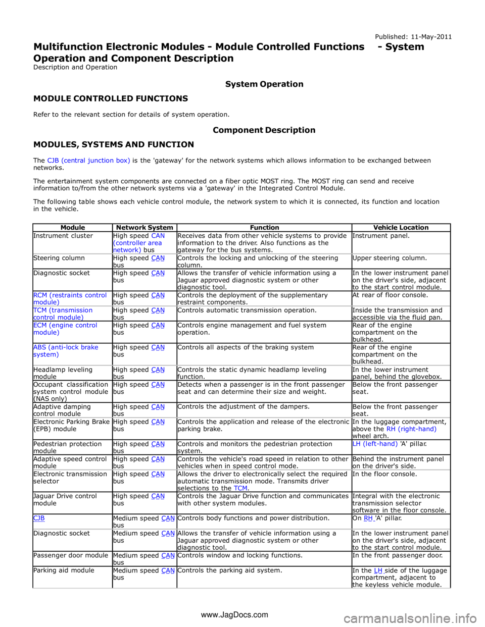
Instrument cluster
High speed CAN
(controller area network) bus Receives data from other vehicle systems to provide
information to the driver. Also functions as the gateway for the bus systems. Instrument panel. Steering column
High speed CAN bus Controls the locking and unlocking of the steering
column. Upper steering column. Diagnostic socket
High speed CAN bus Allows the transfer of vehicle information using a
Jaguar approved diagnostic system or other diagnostic tool. In the lower instrument panel
on the driver's side, adjacent
to the start control module. RCM (restraints control module) High speed CAN bus Controls the deployment of the supplementary
restraint components. At rear of floor console. TCM (transmission
control module) High speed CAN bus Controls automatic transmission operation.
Inside the transmission and
accessible via the fluid pan. ECM (engine control
module) High speed CAN bus Controls engine management and fuel system
operation. Rear of the engine
compartment on the
bulkhead. ABS (anti-lock brake
system) High speed CAN bus Controls all aspects of the braking system
Rear of the engine
compartment on the
bulkhead. Headlamp leveling
module High speed CAN bus Controls the static dynamic headlamp leveling
function. In the lower instrument panel, behind the glovebox. Occupant classification
system control module (NAS only) High speed CAN bus Detects when a passenger is in the front passenger
seat and can determine their size and weight. Below the front passenger
seat. Adaptive damping
control module High speed CAN bus Controls the adjustment of the dampers.
Below the front passenger
seat. Electronic Parking Brake
(EPB) module High speed CAN bus Controls the application and release of the electronic
parking brake. In the luggage compartment,
above the RH (right-hand)
wheel arch. Pedestrian protection
module High speed CAN bus Controls and monitors the pedestrian protection system. LH (left-hand) 'A' pillar. Adaptive speed control
module High speed CAN bus Controls the vehicle's road speed in relation to other
vehicles when in speed control mode. Behind the instrument panel
on the driver's side. Electronic transmission
selector High speed CAN bus Allows the driver to electronically select the required
automatic transmission mode. Transmits driver
selections to the TCM. In the floor console. Jaguar Drive control
module High speed CAN bus Controls the Jaguar Drive function and communicates
with other system modules. Integral with the electronic
transmission selector
software in the floor console. CJB
Medium speed CAN bus Controls body functions and power distribution. On RH 'A' pillar. Diagnostic socket
Medium speed CAN bus Allows the transfer of vehicle information using a
Jaguar approved diagnostic system or other diagnostic tool. In the lower instrument panel
on the driver's side, adjacent
to the start control module. Passenger door module
Medium speed CAN bus Controls window and locking functions. In the front passenger door. Parking aid module
Medium speed CAN bus Controls the parking aid system.
In the LH side of the luggage compartment, adjacent to
the keyless vehicle module. www.JagDocs.com
Page 2449 of 3039

Published: 11-May-2011
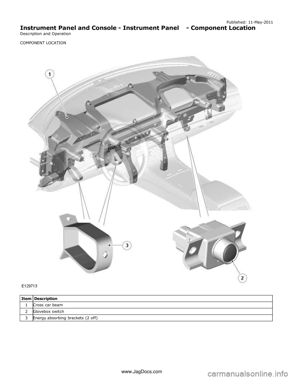
Instrument Panel and Console - Instrument Panel - Component Location
Description and Operation
COMPONENT LOCATION
Item Description 1 Cross car beam 2 Glovebox switch 3 Energy absorbing brackets (2 off) www.JagDocs.com
Page 2451 of 3039

a power supply to operate the glovebox latch to unlock the glovebox.
The glove box opening is inhibited by the CJB if the anti-theft alarm system is armed and if valet mode is selected using the Touch Screen Display (TSD). The CJB detects the voltage signal from the switch but will not operate the glovebox latch if other condition exists.
GLOVEBOX SWITCH DESCRIPTION Component Description
The conventional glove box switch is located behind the instrument panel veneer. The round button of the switch is visible
through an aperture in the veneer.
Two screws hold the switch in position behind the veneer. The veneer panel has two bosses which the screws are threaded
into.