window JAGUAR XFR 2010 1.G User Guide
[x] Cancel search | Manufacturer: JAGUAR, Model Year: 2010, Model line: XFR, Model: JAGUAR XFR 2010 1.GPages: 3039, PDF Size: 58.49 MB
Page 1683 of 3039
Published: 11-May-2011
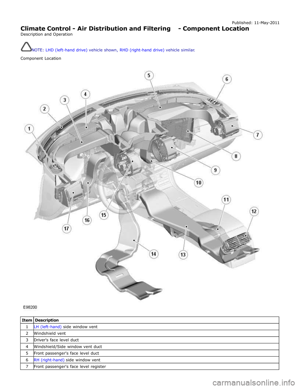
Climate Control - Air Distribution and Filtering - Component Location
Description and Operation
NOTE: LHD (left-hand drive) vehicle shown, RHD (right-hand drive) vehicle similar.
Component Location
Item Description 1 LH (left-hand) side window vent 2 Windshield vent 3 Driver's face level duct 4 Windshield/Side window vent duct 5 Front passenger's face level duct 6 RH (right-hand) side window vent 7 Front passenger's face level register
Page 1687 of 3039
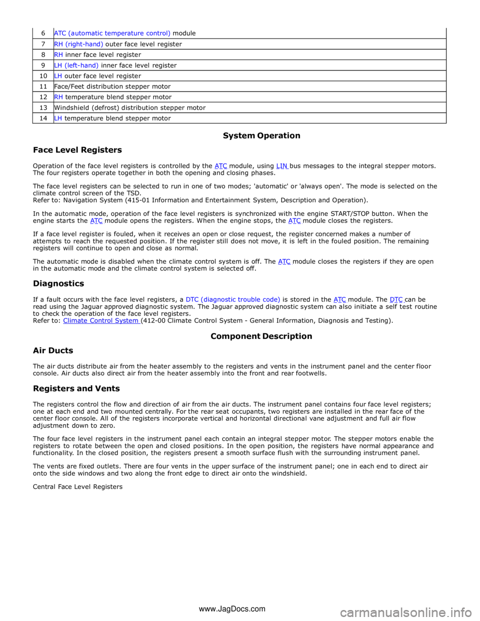
7 RH (right-hand) outer face level register 8 RH inner face level register 9 LH (left-hand) inner face level register 10 LH outer face level register 11 Face/Feet distribution stepper motor 12 RH temperature blend stepper motor 13 Windshield (defrost) distribution stepper motor 14 LH temperature blend stepper motor
Face Level Registers System Operation
Operation of the face level registers is controlled by the ATC module, using LIN bus messages to the integral stepper motors. The four registers operate together in both the opening and closing phases.
The face level registers can be selected to run in one of two modes; 'automatic' or 'always open'. The mode is selected on the
climate control screen of the TSD.
Refer to: Navigation System (415-01 Information and Entertainment System, Description and Operation).
In the automatic mode, operation of the face level registers is synchronized with the engine START/STOP button. When the
engine starts the ATC module opens the registers. When the engine stops, the ATC module closes the registers.
If a face level register is fouled, when it receives an open or close request, the register concerned makes a number of
attempts to reach the requested position. If the register still does not move, it is left in the fouled position. The remaining
registers will continue to open and close as normal.
The automatic mode is disabled when the climate control system is off. The ATC module closes the registers if they are open in the automatic mode and the climate control system is selected off.
Diagnostics
If a fault occurs with the face level registers, a DTC (diagnostic trouble code) is stored in the ATC module. The DTC can be read using the Jaguar approved diagnostic system. The Jaguar approved diagnostic system can also initiate a self test routine
to check the operation of the face level registers.
Refer to: Climate Control System (412-00 Climate Control System - General Information, Diagnosis and Testing).
Air Ducts Component Description
The air ducts distribute air from the heater assembly to the registers and vents in the instrument panel and the center floor
console. Air ducts also direct air from the heater assembly into the front and rear footwells.
Registers and Vents
The registers control the flow and direction of air from the air ducts. The instrument panel contains four face level registers;
one at each end and two mounted centrally. For the rear seat occupants, two registers are installed in the rear face of the
center floor console. All of the registers incorporate vertical and horizontal directional vane adjustment and full air flow
adjustment down to zero.
The four face level registers in the instrument panel each contain an integral stepper motor. The stepper motors enable the
registers to rotate between the open and closed positions. In the open position, the registers have normal appearance and
functionality. In the closed position, the registers present a smooth surface flush with the surrounding instrument panel.
The vents are fixed outlets. There are four vents in the upper surface of the instrument panel; one in each end to direct air
onto the side windows and two along the front edge to direct air onto the windshield.
Central Face Level Registers
www.JagDocs.com
Page 1706 of 3039
Climate Control - Control Components - Overview
Description and Operation
Overview Published: 11-May-2011
The climate control system is controlled by the ATC (automatic temperature control) module. It controls the heating and
ventilation system and the A/C (air conditioning) system to regulate the temperature, volume and distribution of air into the
passenger compartment. The system is a fully automatic dual zone system capable of maintaining individual temperature
levels selected for the LH (left-hand) and RH (right-hand) sides of the passenger compartment, up to a maximum differential
of approximately 3 ºC (5.4 ºF). Manual overrides for the system include inlet air source, blower speed and air distribution.
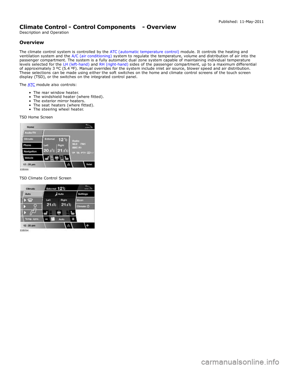
These selections can be made using either the soft switches on the home and climate control screens of the touch screen
display (TSD), or the switches on the integrated control panel.
The ATC module also controls: The rear window heater.
The windshield heater (where fitted).
The exterior mirror heaters.
The seat heaters (where fitted).
The steering wheel heater.
TSD Home Screen
TSD Climate Control Screen
Page 1707 of 3039
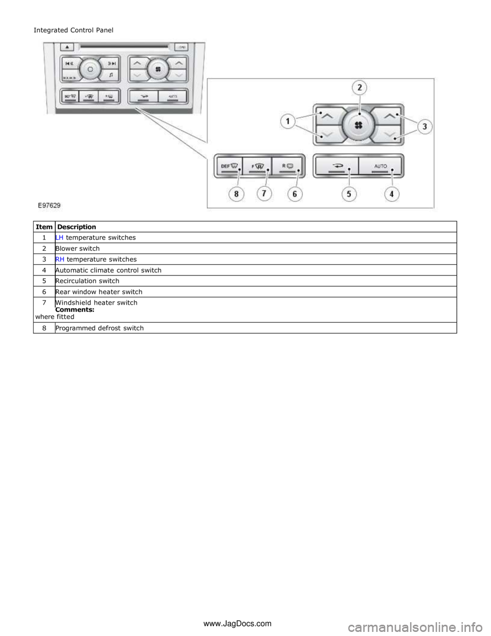
1 LH temperature switches 2 Blower switch 3 RH temperature switches 4 Automatic climate control switch 5 Recirculation switch 6 Rear window heater switch 7 Windshield heater switch Comments:
where fitted 8 Programmed defrost switch Integrated Control Panel
www.JagDocs.com
Page 1710 of 3039
control switch on the integrated control panel or the + and - soft buttons on the touch screen display (TSD). The ATC module also adjusts blower speed to compensate for the ram effect on inlet air produced by forward movement of the vehicle. As
vehicle speed and ram effect increases, blower motor speed is reduced, and vice versa.
Air Distribution Control
Two air distribution doors are used to direct air into the passenger compartment. The doors are operated by stepper motors,
which are controlled by the ATC module using LIN bus messages.
When the A/C system is in automatic mode, the ATC module automatically controls air distribution into the passenger compartment in line with its 'comfort' algorithm. Automatic control is overridden if any of the TSD air distribution soft buttons
are selected. Air distribution in the passenger compartment will remain as selected until the 'Auto' switch is pressed or a
different manual selection is made.
A/C Compressor Control
When A/C is selected the ATC module maintains the evaporator at an operating temperature that varies with the passenger compartment cooling requirements. If the requirement for cooled air decreases, the ATC module raises the evaporator operating temperature by reducing the flow of refrigerant provided by the A/C compressor. The ATC module closely controls the rate of temperature increase to avoid introducing moisture into the passenger compartment.
If the requirement for cooled air increases, the ATC module lowers the evaporator operating temperature by increasing the flow of refrigerant provided by the A/C compressor.
When A/C is off, the compressor current signal supplied by the ATC module holds the A/C compressor solenoid valve in the minimum flow position, effectively switching off the A/C function.
The ATC module incorporates limits for the operating pressure of the refrigerant system. If the system approaches the high pressure limit, the compressor current signal is progressively reduced until the system pressure decreases. If the system falls
below the low pressure limit, the compressor current signal is held at its lowest setting so that the A/C compressor is maintained at its minimum stroke. This avoids depletion of the lubricant from the A/C compressor.
A/C Compressor Torque
The ATC module transmits refrigerant pressure and A/C compressor current values to the ECM (engine control module) over the medium speed then high speed CAN bus, using the CJB as a gateway. The ECM uses these values to calculate the torque being used to drive the A/C compressor. The ECM compares the calculated value with its allowable value and if necessary forces the ATC module to inhibit the A/C compressor by transmitting the 'ACClutchInhibit' CAN message. This forces the ATC module to reduce the drive current to the A/C compressor solenoid valve, which reduces refrigerant flow. This in turn reduces the torque required to drive the A/C compressor.
By reducing the maximum A/C compressor torque, the ECM is able to reduce the load on the engine when it needs to maintain vehicle performance or cooling system integrity.
Cooling Fan Control
The ATC module determines the amount of condenser cooling required from the refrigerant pressure sensor, since there is a direct relationship between the temperature and pressure of the refrigerant. The cooling requirement is broadcast to the ECM on the medium speed CAN bus. The ECM then controls the temperature of the condenser using the cooling fan.
Programmed Defrost
The programmed defrost DEF switch is located on the integrated control panel. When the switch is pressed, the ATC module instigates the programmed defrost function. When selected, the ATC module configures the system as follows:
Automatic mode off.
A/C on. Selected temperature unchanged.
Air inlet set to fresh air.
Air distribution set to windshield.
Blower speed set to level 6.
Windshield heater (where fitted) and rear window heater on.
The programmed defrost function can be cancelled by one of the following:
Selecting any air distribution switch on the TSD.
Pressing the AUTO switch on the integrated control panel.
A second press of the DEF button.
Switching the ignition OFF.
The blower speed can be adjusted without terminating the programmed defrost function.
Rear Window Heater
Rear window heater operation is only enabled when the engine is running. The ATC module controls operation of the rear window heater using a relay in the RJB. When rear window heater operation is required, the ATC module broadcasts a message to the RJB on the medium speed CAN bus. On receipt of the message, the RJB energizes the relay by providing a ground path for the relay coil. This allows a battery feed to flow across the relay to power the rear window heater element.
Page 1711 of 3039
rear window heater switch is pressed or the engine stops.
Automatic operation during a journey is initiated when low ambient air temperatures are experienced and the vehicle has been
travelling for a set period of time above a threshold speed. In this instance, no feedback is given to the driver to inform him
the rear window heater is operational (the switch LED is not illuminated). The duration of heater operation is variable depending on the ambient air temperature, vehicle speed and the amount of time the vehicle has been travelling.
Windshield Heater (Where Fitted)
Windshield heater operation is only enabled when the engine is running. The ATC module controls operation of the windshield heater using two relays in the EJB (engine junction box). When windshield heater operation is required, the ATC module broadcasts a message to the CJB on the medium speed CAN bus. On receipt of the message, the CJB energizes the relays by providing a ground path for both relay coils. This allows a battery feed to flow across the relays to power the windshield left
and right heater elements.
There are two modes of windshield heater operation; manual and automatic.
Manual operation is activated by pressing the windshield heater switch on the integrated control panel. When the switch is
pressed, the status LED in the switch illuminates and the windshield heater elements are energized. Manual operation is discontinued when the windshield heater switch is pressed a second time, 5 minutes have elapsed (the heating phase), or the
engine stops. If manual operation is discontinued by the engine stopping, the previous heating phase is resumed if the engine
is re-started within 30 seconds.
There are two variants of automatic operation; automatic operation at the start of a journey and automatic operation during a
journey.
Automatic operation at the start of a journey is initiated if the ambient air temperature is below 5 °C (41 °F). In this instance,
the switch LED is illuminated and the heater elements are energized for 6.5 minutes. Automatic operation is discontinued if the windshield heater switch is pressed or the engine stops.
Automatic operation during a journey is initiated when low ambient air temperatures are experienced and the vehicle has been
travelling for a set period of time above a threshold speed. In this instance, no feedback is given to the driver to inform him
the windshield heater is operational (the switch LED is not illuminated) and the duration of operation is variable depending upon the ambient air temperature, vehicle speed and the amount of time the vehicle has been travelling.
Exterior Mirror Heaters
Operation of the exterior mirror heaters is fully automatic and not controllable by the driver. Exterior mirror heater operation is
determined by ambient air temperature and windshield wiper status. When ambient air temperature reaches a pre-determined
level, the ATC module broadcasts an exterior mirror heating request to the door modules over the medium speed CAN bus. On receipt of this message, the door modules provide feed and ground connections to both exterior mirror heater elements.
The amount of time the exterior mirror heaters are operational increases if the windshield wipers are switched on. This ensures
the mirrors remain mist free in damp and wet conditions, where there is an increased risk of misting.
Seat Heaters (Where Fitted)
There are four seat heater settings available; off, 1, 2 and 3, which can be selected on the home and climate control screens
of the TSD. The heat setting is relayed to the vehicle occupants through a graduated display on the TSD.
Operation of the heated seats is controlled by the ATC module. When the ATC module receives a heating request from the TSD, it broadcasts a message to the CJB over the medium speed CAN bus. The CJB then provides a hardwired 12 V supply to the three heater elements in the related front seat. The heater elements, two in the seat cushion and one in the seat squab,
are wired in series. The ATC module monitors seat temperature using a temperature sensor located in each seat cushion. The CJB provides the temperature sensors with a 5 V supply. The level of the returned voltage back to the CJB is proportional to the seat temperature. The value of the return signal is broadcast to the ATC module, over the medium speed CAN bus, which allows it to control the seat temperature to the required level. The ATC module will suspend or disable operation of the seat heaters if any of the following occur:
Battery voltage exceeds 16.5 ± 0.3 V for more than 5 seconds. Seat heating is re-enabled when battery voltage
decreases to 16.2 ± 0.3 V.
If a short or open circuit is detected.
If the seat heat temperature rises significantly above the target temperature setting.
The graduated display on the TSD remains illuminated until the seat heaters are turned off or the engine stops. If the engine
is restarted within 30 seconds the seat heater resumes the previous heating level.
Page 1802 of 3039

DTC Description Possible Cause Action programming state
Attempted to program a non
default key
Instrument cluster Cold init
whilst in Ignition On state,
without key being present in
the SCU
Race condition caused by
closing driver door and
pressing the start button
within a small time window
Passive Key search function
from last door closed and key
inserted in the SCU instrument cluster. Design condition - advise customer of
starting sequence. Design condition - determine customer
transponder key usage B1B0187 Key Transponder
LIN fault
Instrument cluster power and
ground supply circuits - short,
open circuit
Smartcard docking station
power and ground supply
circuits - short, open circuit Carry out any pinpoint tests associated with this DTC using
the manufacturer approved diagnostic system. Check LIN
communications between smartcard docking station and
instrument cluster. Refer to the electrical circuit diagrams
and check smartcard docking station power and ground
supply circuits for short, open circuit and instrument cluster
power and ground supply circuits for short, open circuit B1B3305
Target I.D.
Transfer
CAN fault
ECM ignition, power and
ground supply circuits - short,
open circuit
Instrument cluster power and
ground supply circuits - short,
open circuit
ECM or instrument cluster
incorrectly configured Carry out any pinpoint tests associated with this DTC using
the manufacturer approved diagnostic system. Check CAN
communications between ECM and instrument cluster. Refer
to electrical circuit diagrams and check ECM ignition, power
and ground supply circuits for short, open circuit and
instrument cluster power and ground supply circuits for short,
open circuit. Perform the Immobilisation application from the
Set-up menu using the manufacturer approved diagnostic
system B1B3362
Target I.D.
Transfer
CAN fault
ECM ignition, power and
ground supply circuits - short,
open circuit
Instrument cluster power and
ground supply circuits - short,
open circuit
Incorrect ECM or instrument
cluster installed
Synchronisation error following
re-programming
Noise/EMC related error Carry out any pinpoint tests associated with this DTC using
the manufacturer approved diagnostic system. Check CAN
communications between ECM and instrument cluster. Refer
to electrical circuit diagrams and check ECM ignition, power
and ground supply circuits for short, open circuit and
instrument cluster power and ground supply circuits for short,
open circuit. Check correct ECM and instrument cluster
installed. Perform the Immobilisation application from the
Set-up menu using the manufacturer approved diagnostic
system. Check CAN network for interference/EMC related
issues B1B3364
Target
identification
transfer
Algorithm based failure -
signal plausibility failure
CAN fault
ECM ignition, power and
ground supply circuits - short,
open circuit
Instrument cluster power and
ground supply circuits - short,
open circuit
electronic steering column lock
status incomplete
Race condition caused by
closing driver door and
pressing the start button
within a small time window If the customer has not reported a non start issue, clear the
DTC and check vehicle starts correctly. If a non start has
been reported run the manufacturers approved diagnostic
system Start Authorisation Application and follow the actions
required for this DTC. Carry out any pinpoint tests associated
with this DTC using the manufacturer approved diagnostic
system. Check CAN communications between ECM and
instrument cluster. Refer to electrical circuit diagrams and
check ECM ignition, power and ground supply circuits for
short, open circuit and instrument cluster power and ground
supply circuits for short, open circuit. Check electronic
steering column lock operation. Advise customer of starting
sequence and to allow time to elapse between closing door
and pressing start button. B1B3387
Target I.D.
Transfer
CAN fault
ECM ignition, power and
ground supply circuits - short,
open circuit
Instrument cluster power and
ground supply circuits - short,
open circuit
Low battery voltage Carry out any pinpoint tests associated with this DTC using
the manufacturer approved diagnostic system. Check CAN
communications between ECM and instrument cluster. Refer
to electrical circuit diagrams and check ECM ignition, power
and ground supply circuits for short, open circuit and
instrument cluster power and ground supply circuits for short,
open circuit. Check battery is in serviceable condition and is
fully charged, check terminals etc www.JagDocs.com
Page 1903 of 3039
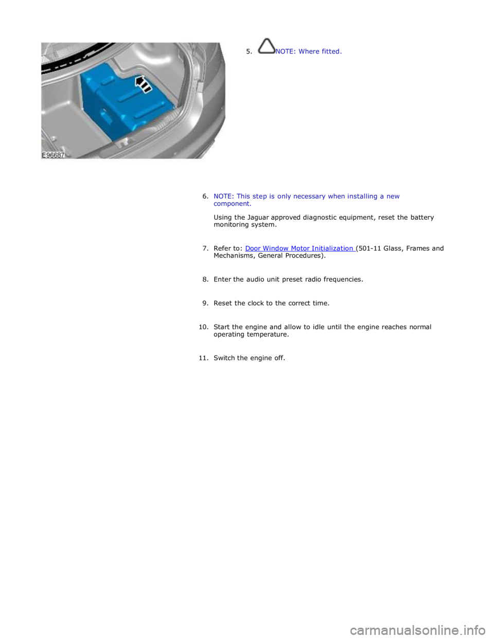
5. NOTE: Where fitted.
6. NOTE: This step is only necessary when installing a new
component.
Using the Jaguar approved diagnostic equipment, reset the battery
monitoring system.
7. Refer to: Door Window Motor Initialization (501-11 Glass, Frames and Mechanisms, General Procedures).
8. Enter the audio unit preset radio frequencies.
9. Reset the clock to the correct time.
10. Start the engine and allow to idle until the engine reaches normal
operating temperature.
11. Switch the engine off.
Page 1907 of 3039
Installation
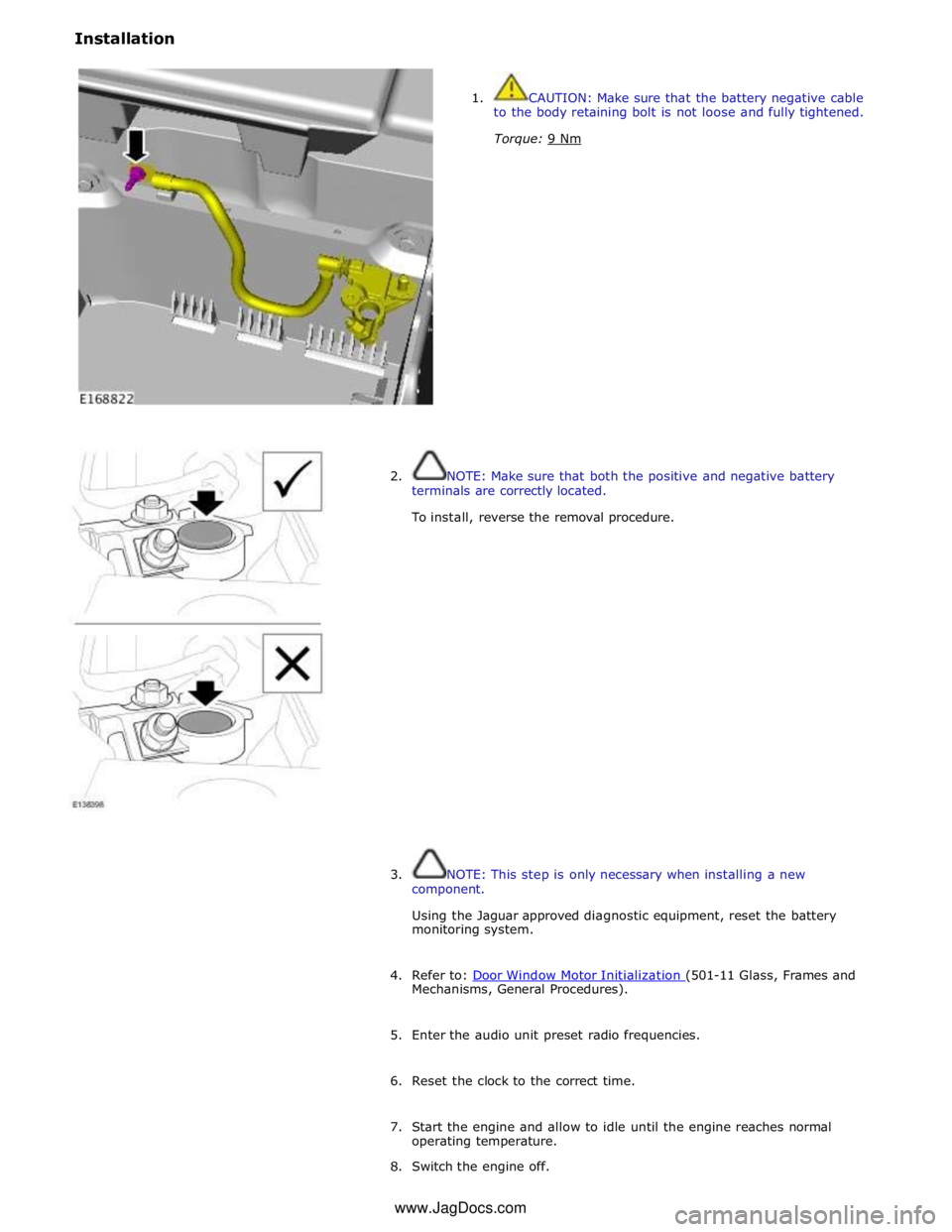
1. CAUTION: Make sure that the battery negative cable
to the body retaining bolt is not loose and fully tightened.
Torque: 9 Nm
2. NOTE: Make sure that both the positive and negative battery
terminals are correctly located.
To install, reverse the removal procedure.
3. NOTE: This step is only necessary when installing a new
component.
Using the Jaguar approved diagnostic equipment, reset the battery
monitoring system.
4. Refer to: Door Window Motor Initialization (501-11 Glass, Frames and Mechanisms, General Procedures).
5. Enter the audio unit preset radio frequencies.
6. Reset the clock to the correct time.
7. Start the engine and allow to idle until the engine reaches normal
operating temperature.
8. Switch the engine off. www.JagDocs.com
Page 1945 of 3039

player is only compatible with standard CD's. All other versions of CD player are compatible with standard CDs and CDs with MP3 or WMA (windows media audio) files.
A portable audio module allows for the connection of a range of portable audio devices to the car’s audio system. The portable
audio module is controlled through the IAM (integrated audio module) and Touch-screen with play back through the car’s
speaker system. The introduction of this system allows the user to import their personal portable media player to interface
with the car, including iPod and other MP3 players, or USB mass storage devices such as memory sticks. MP3 players can also
be controlled through the Touch-screen if they are configured as mass storage devices. Details of how to do this will be
contained in the manufacturers instructions.
The chosen audio device can be plugged into the car using an interface panel located in the floor console between the front
seats. The interface includes a 3.5mm auxiliary jack-plug socket, a 12-volt power supply, a dedicated iPod connector with
charging function, plus a USB2 connector which allows connectivity for a wide variety of USB devices. The USB port also
provides a charging function although it does not support a USB hub. The maximum charging current supplied is 500ma. The
user can connect an iPod and USB device at the same time, changing the source via the Touch-screen. The non selected source
will still charge.
The Jaguar Sound System is the basic audio system which comprises of an IAM (integrated audio module) with no external
amplifier and 8 speakers.
The Jaguar 320W Premium Sound System has the addition of an AUD 8 power amplifier and a 9 speaker system.
The Bowers & Wilkins 440w Surround Sound System additions include an AUD 12 power amplifier, a Dolby Pro-Logic 2 7.1
Surround Sound System, and 14 speakers.
DAB (digital audio broadcasting) is available for most European markets and gives access to digital radio channels for better
sound quality and enhanced functionality depending on local service availability. The DAB (digital audio broadcasting) module
is located in the luggage compartment. The system receives reception signals from the following sources to ensure optimum
signal strength.
DAB band L antenna located in the roof pod antenna module
DAB band III antenna located in the heated rear window.
For NAS vehicles the digital format adopted is satellite radio which specifically links to the Sirius network. The system operates
in the S-band frequency range, and as a result of the use of satellite transmission, has the ability to provide CD quality audio broadcasts over very large areas (typically continents). The satellite radio receiver is located in the luggage compartment. The
system receives reception signals from the satellite radio antenna located in the roof pod module.
Primary user control of the audio system is via the ICP (integrated control panel) and the Touch-screen which are located in the
center of the instrument panel. Control signals from the ICP (integrated control panel) are relayed on the medium speed CAN
(controller area network) bus to the ICM (information control module). The ICM (information control module) relays the control
signals to the rest of the audio system on the MOST (media oriented systems transport) ring. The ICM (information control
module) is the timing master for the MOST (media oriented systems transport) ring and also hosts a gateway function between
the medium speed CAN bus and the MOST (media oriented systems transport) ring. Audio output signals on the Jaguar 320W Premium Sound System and Bowers & Wilkins 440W Surround Sound System are sent on the MOST (media oriented systems
transport) ring from the IAM (integrated audio module) to the power amplifier for speaker output. www.JagDocs.com