diagram JAGUAR XFR 2010 1.G Workshop Manual
[x] Cancel search | Manufacturer: JAGUAR, Model Year: 2010, Model line: XFR, Model: JAGUAR XFR 2010 1.GPages: 3039, PDF Size: 58.49 MB
Page 2067 of 3039

Published: 11-May-2011
Module Communications Network - Communications Network - Overview
Description and Operation
OVERVIEW
A number of different types of communication network are incorporated into the vehicle wiring harnesses for the transmission
of commands and information between control modules. The configuration installed on a particular vehicle depends on the
model and equipment level.
NOTE: The control diagrams shown later in this section are schematics reflecting communications networks fitted to LH
(left-hand) vehicles only. For detailed layouts of the various communications networks fitted to LHD (left-hand drive) and RHD
(right-hand drive) vehicles, refer to the Electrical Guide.
The communications networks available on the vehicle are shown in the table below.
Network Baud Rate LIN (local interconnect network) bus 9.6 kbits/s Medium speed CAN (controller area network) bus 125 kbits/s High speed CAN bus 500 kbits/s Media Orientated System Transport (MOST) ring 24 mbits/s
Page 2068 of 3039

Published: 11-May-2011
Module Communications Network - Communications Network - System
Operation and Component Description
Description and Operation
Control Diagram
NOTE:
CONTROL DIAGRAM - LIN BUS - SHEET 1 OF 2
Item Description O = LIN (local interconnect network) bus 1 CJB (central junction box) 2 Battery backed sounder 3 Intrusion detection module
Page 2070 of 3039

O = LIN bus 1 ATC (automatic temperature control) module 2 Stepper motor - Windshield defrost 3 Stepper motor - Face/feet distribution 4 Stepper motor - LH (left-hand) temperature blend 5 Stepper motor - RH (right-hand) temperature blend 6 Electric booster heater 7 Stepper motor - RH outer face level vent 8 Stepper motor - RH inner face level vent 9 Stepper motor - LH inner face level vent 10 Stepper motor - LH outer face level vent CONTROL DIAGRAM - LIN BUS - SHEET 2 OF 2
www.JagDocs.com
Page 2072 of 3039
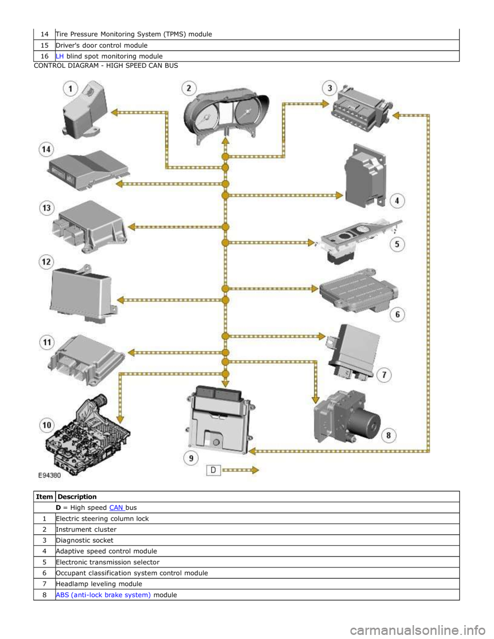
Tire Pressure Monitoring System (TPMS) module 15 Driver's door control module 16 LH blind spot monitoring module CONTROL DIAGRAM - HIGH SPEED CAN BUS
Item Description D = High speed CAN bus 1 Electric steering column lock 2 Instrument cluster 3 Diagnostic socket 4 Adaptive speed control module 5 Electronic transmission selector 6 Occupant classification system control module 7 Headlamp leveling module 8 ABS (anti-lock brake system) module
Page 2073 of 3039
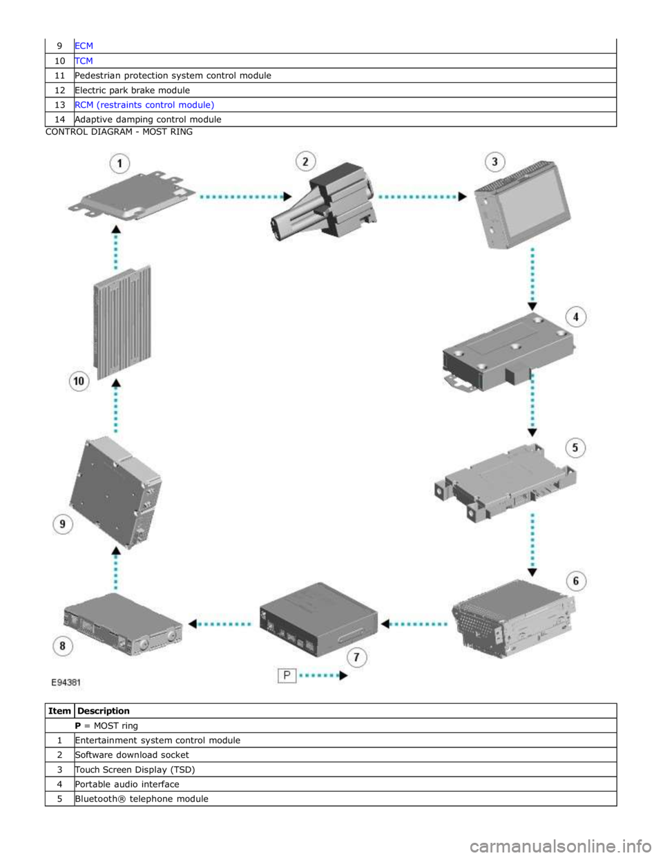
10 TCM 11 Pedestrian protection system control module 12 Electric park brake module 13 RCM (restraints control module) 14 Adaptive damping control module CONTROL DIAGRAM - MOST RING
Item Description P = MOST ring 1 Entertainment system control module 2 Software download socket 3 Touch Screen Display (TSD) 4 Portable audio interface 5 Bluetooth® telephone module
Page 2076 of 3039

CAN Harness Architecture
For a detailed description of the CAN Networks and architecture, refer to the relevant Description and Operation section in the
Workshop Manual.
CAN Network Integrity Tests
If a control module is suspected of non-communication, the Network Integrity test application available on the manufacturer
approved diagnostic system can be used to confirm if communication is possible between the control modules on the vehicle
and the manufacturer approved diagnostic system (via the J1962 diagnostic connector ). The results from the test can be used
to determine if either a single module or multiple modules are failing to communicate.
CAN Terminating Modules
If the Network Integrity test indicates that one or more module on one of the CAN networks (HS or MS) are failing to
communicate, there are several checks that can be made. The first step is to identify if both of the CAN terminating modules
on each individual CAN Bus are communicating. If both CAN terminating modules for each individual CAN Bus are
communicating (identified via the Network Integrity test), then it can be confirmed that the main 'backbone' of the CAN
harness is complete. The main 'backbone' of the CAN harness consists of all the modules connected to the CAN harness via a
'loop' configuration and also includes the two terminating modules.
Communication with both CAN terminating modules via the Network Integrity test confirms the physical integrity of the main
'backbone' of the CAN harness (and the harness spur to the J1962 diagnostic connector). This means that there is no
requirement to check the resistance of the CAN Network. This is because the standard check for 60 ohms across the CAN High
and CAN Low lines will not provide any additional information regarding the physical condition of the CAN harness, beyond
what has already been determined from the Network Integrity test.
Non-Communication of a Terminating Module
If a Network Integrity test reveals a terminating module is failing to communicate it can indicate a break in the main
'backbone' of the CAN harness. The first checks should always be to confirm the power and ground supplies to the
non-communicating module are correct. Providing these are correct, the resistance between the CAN High and CAN Low lines at
the J1962 connector can be checked to determine the integrity of the main 'backbone' of the CAN harness. After disconnecting
the battery a reading of 120 ohms would indicate an open circuit in the main 'backbone' of the CAN harness. Alternatively, a
reading of 60 ohms would indicate that there is no open circuit fault with the main 'backbone' of the CAN harness.
It is worth noting that even if one of the terminating modules is disconnected from the CAN harness, communications between
the modules still connected may still be possible. Therefore communication between the manufacturer approved diagnostic
system and the connected modules may also be possible.
Locating CAN Harness Open Circuits
In the case where multiple modules, including a terminating module, are failing to communicate, having first confirmed the
power and ground supplies are correct, the approximate location of the open circuit can be identified from analysis of the
Network Integrity test results and reference to the relevant CAN network circuit diagrams. For example, if an open circuit
existed in a certain position on the CAN harness, any module positioned on the Network between the J1962 connector and the
open circuit should return a response during the Network Integrity test. No responses would be returned from any modules
past the open circuit fault in the Network.
CAN Harness 'Spur' Type Configuration Circuits
If, after the initial checks (Network Integrity test using the manufacturer approved diagnostic system, and power and ground
supplies to the module have been checked and confirmed as correct), a module that is connected to the CAN harness via a
'spur' type configuration is suspected of not communicating, then the physical integrity of the CAN harness 'spur' can be
checked.
This is most easily undertaken by individually checking the continuity of the CAN High and CAN Low lines between the
non-communicating module connector (with the module disconnected) and the J1962 diagnostic connector.
'Lost Communications' DTCs
As well as the methods described so far in this document, which can be used to determine the location of an open circuit in
the CAN harness, 'Lost Communications' DTCs can also be used for this purpose. Lost communication DTCs mean that a
module is not receiving CAN information from another module.
For example, if a global DTC read were to be carried out, only DTCs stored in the modules that the manufacturer approved
diagnostic system could communicate with would be displayed. If there was an open circuit fault in a certain position on the
CAN harness, the modules that could display DTCs would all be prior to the open circuit on the Network, and these modules
should display 'Lost Communications' DTCs with all the modules located on the Network past the open circuit fault.
'Bus off' DTCs
The references to bus and its condition refer to the network concerned and the modules on that network.
If a module logs a 'Bus Off' DTC, it means that the module has detected CAN transmission errors and has disabled it's own
CAN transmissions and disconnected itself from the network in an attempt to allow the rest of the network to function. At this
point the 'Bus Off' DTC is set. A common cause of 'Bus Off' DTCs can be a short circuit in the CAN network.
Page 2080 of 3039
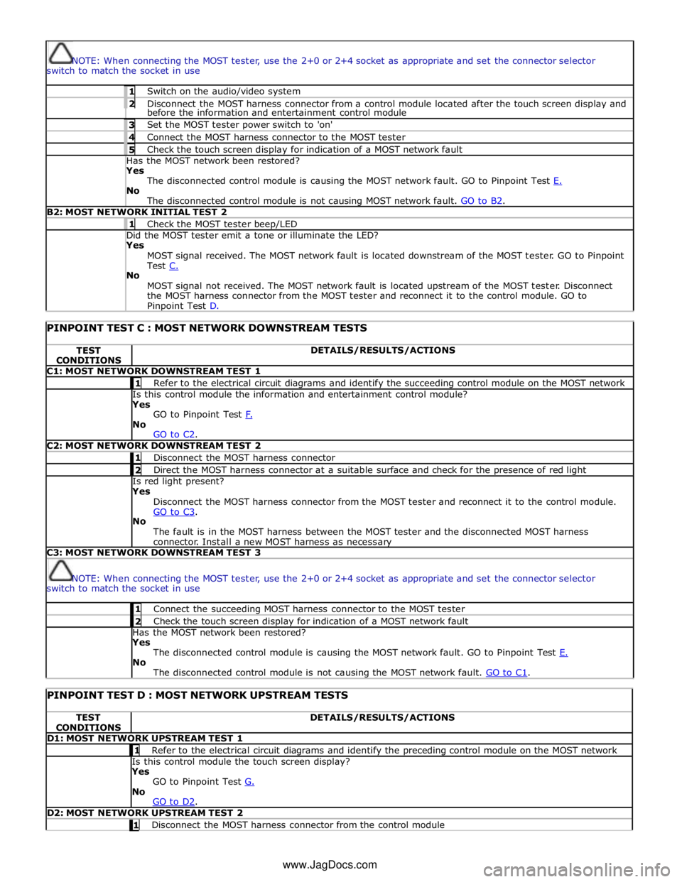
NOTE: When connecting the MOST tester, use the 2+0 or 2+4 socket as appropriate and set the connector selector
switch to match the socket in use 1 Switch on the audio/video system 2 Disconnect the MOST harness connector from a control module located after the touch screen display and before the information and entertainment control module 3 Set the MOST tester power switch to 'on' 4 Connect the MOST harness connector to the MOST tester 5 Check the touch screen display for indication of a MOST network fault Has the MOST network been restored? Yes
The disconnected control module is causing the MOST network fault. GO to Pinpoint Test E. No
The disconnected control module is not causing MOST network fault. GO to B2. B2: MOST NETWORK INITIAL TEST 2 1 Check the MOST tester beep/LED Did the MOST tester emit a tone or illuminate the LED? Yes
MOST signal received. The MOST network fault is located downstream of the MOST tester. GO to Pinpoint
Test C. No
MOST signal not received. The MOST network fault is located upstream of the MOST tester. Disconnect
the MOST harness connector from the MOST tester and reconnect it to the control module. GO to Pinpoint Test D.
PINPOINT TEST C : MOST NETWORK DOWNSTREAM TESTS TEST
CONDITIONS DETAILS/RESULTS/ACTIONS C1: MOST NETWORK DOWNSTREAM TEST 1 1 Refer to the electrical circuit diagrams and identify the succeeding control module on the MOST network Is this control module the information and entertainment control module?
Yes
GO to Pinpoint Test F. No
GO to C2. C2: MOST NETWORK DOWNSTREAM TEST 2 1 Disconnect the MOST harness connector 2 Direct the MOST harness connector at a suitable surface and check for the presence of red light Is red light present?
Yes
Disconnect the MOST harness connector from the MOST tester and reconnect it to the control module.
GO to C3. No
The fault is in the MOST harness between the MOST tester and the disconnected MOST harness
connector. Install a new MOST harness as necessary C3: MOST NETWORK DOWNSTREAM TEST 3
NOTE: When connecting the MOST tester, use the 2+0 or 2+4 socket as appropriate and set the connector selector
switch to match the socket in use 1 Connect the succeeding MOST harness connector to the MOST tester 2 Check the touch screen display for indication of a MOST network fault Has the MOST network been restored?
Yes
The disconnected control module is causing the MOST network fault. GO to Pinpoint Test E. No
The disconnected control module is not causing the MOST network fault. GO to C1.
PINPOINT TEST D : MOST NETWORK UPSTREAM TESTS TEST
CONDITIONS DETAILS/RESULTS/ACTIONS D1: MOST NETWORK UPSTREAM TEST 1 1 Refer to the electrical circuit diagrams and identify the preceding control module on the MOST network Is this control module the touch screen display?
Yes
GO to Pinpoint Test G. No
GO to D2. D2: MOST NETWORK UPSTREAM TEST 2 1 Disconnect the MOST harness connector from the control module www.JagDocs.com
Page 2081 of 3039
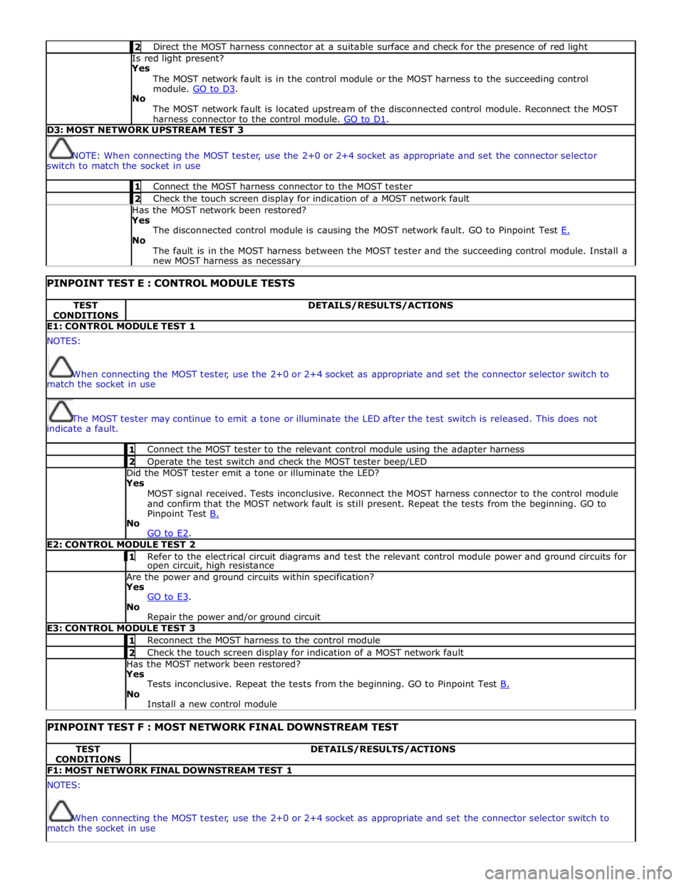
2 Direct the MOST harness connector at a suitable surface and check for the presence of red light Is red light present?
Yes
The MOST network fault is in the control module or the MOST harness to the succeeding control
module. GO to D3. No
The MOST network fault is located upstream of the disconnected control module. Reconnect the MOST
harness connector to the control module. GO to D1. D3: MOST NETWORK UPSTREAM TEST 3
NOTE: When connecting the MOST tester, use the 2+0 or 2+4 socket as appropriate and set the connector selector
switch to match the socket in use 1 Connect the MOST harness connector to the MOST tester 2 Check the touch screen display for indication of a MOST network fault Has the MOST network been restored?
Yes
The disconnected control module is causing the MOST network fault. GO to Pinpoint Test E. No
The fault is in the MOST harness between the MOST tester and the succeeding control module. Install a
new MOST harness as necessary
PINPOINT TEST E : CONTROL MODULE TESTS TEST
CONDITIONS DETAILS/RESULTS/ACTIONS E1: CONTROL MODULE TEST 1 NOTES:
When connecting the MOST tester, use the 2+0 or 2+4 socket as appropriate and set the connector selector switch to
match the socket in use
The MOST tester may continue to emit a tone or illuminate the LED after the test switch is released. This does not
indicate a fault. 1 Connect the MOST tester to the relevant control module using the adapter harness 2 Operate the test switch and check the MOST tester beep/LED Did the MOST tester emit a tone or illuminate the LED? Yes
MOST signal received. Tests inconclusive. Reconnect the MOST harness connector to the control module
and confirm that the MOST network fault is still present. Repeat the tests from the beginning. GO to
Pinpoint Test B. No
GO to E2. E2: CONTROL MODULE TEST 2 1 Refer to the electrical circuit diagrams and test the relevant control module power and ground circuits for open circuit, high resistance Are the power and ground circuits within specification? Yes
GO to E3. No
Repair the power and/or ground circuit E3: CONTROL MODULE TEST 3 1 Reconnect the MOST harness to the control module 2 Check the touch screen display for indication of a MOST network fault Has the MOST network been restored? Yes
Tests inconclusive. Repeat the tests from the beginning. GO to Pinpoint Test B. No
Install a new control module
PINPOINT TEST F : MOST NETWORK FINAL DOWNSTREAM TEST TEST
CONDITIONS DETAILS/RESULTS/ACTIONS F1: MOST NETWORK FINAL DOWNSTREAM TEST 1 NOTES:
When connecting the MOST tester, use the 2+0 or 2+4 socket as appropriate and set the connector selector switch to
match the socket in use
Page 2083 of 3039
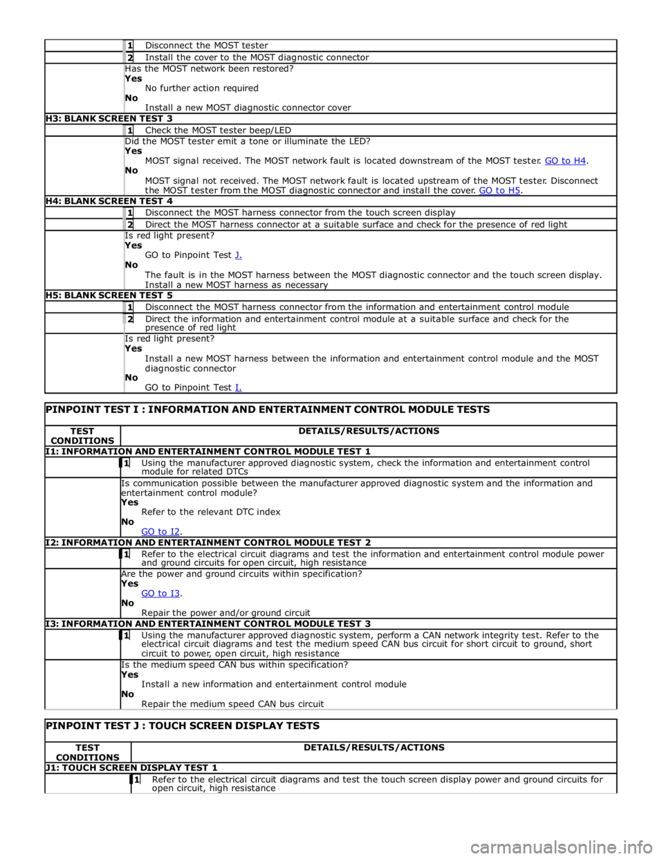
1 Disconnect the MOST tester 2 Install the cover to the MOST diagnostic connector Has the MOST network been restored? Yes
No further action required
No
Install a new MOST diagnostic connector cover H3: BLANK SCREEN TEST 3 1 Check the MOST tester beep/LED Did the MOST tester emit a tone or illuminate the LED? Yes
MOST signal received. The MOST network fault is located downstream of the MOST tester. GO to H4. No
MOST signal not received. The MOST network fault is located upstream of the MOST tester. Disconnect
the MOST tester from the MOST diagnostic connector and install the cover. GO to H5. H4: BLANK SCREEN TEST 4 1 Disconnect the MOST harness connector from the touch screen display 2 Direct the MOST harness connector at a suitable surface and check for the presence of red light Is red light present? Yes
GO to Pinpoint Test J. No
The fault is in the MOST harness between the MOST diagnostic connector and the touch screen display.
Install a new MOST harness as necessary H5: BLANK SCREEN TEST 5 1 Disconnect the MOST harness connector from the information and entertainment control module 2 Direct the information and entertainment control module at a suitable surface and check for the presence of red light Is red light present? Yes
Install a new MOST harness between the information and entertainment control module and the MOST
diagnostic connector
No
GO to Pinpoint Test I.
PINPOINT TEST I : INFORMATION AND ENTERTAINMENT CONTROL MODULE TESTS TEST
CONDITIONS DETAILS/RESULTS/ACTIONS I1: INFORMATION AND ENTERTAINMENT CONTROL MODULE TEST 1 1 Using the manufacturer approved diagnostic system, check the information and entertainment control module for related DTCs Is communication possible between the manufacturer approved diagnostic system and the information and
entertainment control module? Yes
Refer to the relevant DTC index
No
GO to I2. I2: INFORMATION AND ENTERTAINMENT CONTROL MODULE TEST 2 1 Refer to the electrical circuit diagrams and test the information and entertainment control module power and ground circuits for open circuit, high resistance Are the power and ground circuits within specification? Yes
GO to I3. No
Repair the power and/or ground circuit I3: INFORMATION AND ENTERTAINMENT CONTROL MODULE TEST 3 1 Using the manufacturer approved diagnostic system, perform a CAN network integrity test. Refer to the electrical circuit diagrams and test the medium speed CAN bus circuit for short circuit to ground, short
circuit to power, open circuit, high resistance Is the medium speed CAN bus within specification? Yes
Install a new information and entertainment control module
No
Repair the medium speed CAN bus circuit
PINPOINT TEST J : TOUCH SCREEN DISPLAY TESTS TEST
CONDITIONS DETAILS/RESULTS/ACTIONS J1: TOUCH SCREEN DISPLAY TEST 1 1 Refer to the electrical circuit diagrams and test the touch screen display power and ground circuits for open circuit, high resistance
Page 2084 of 3039
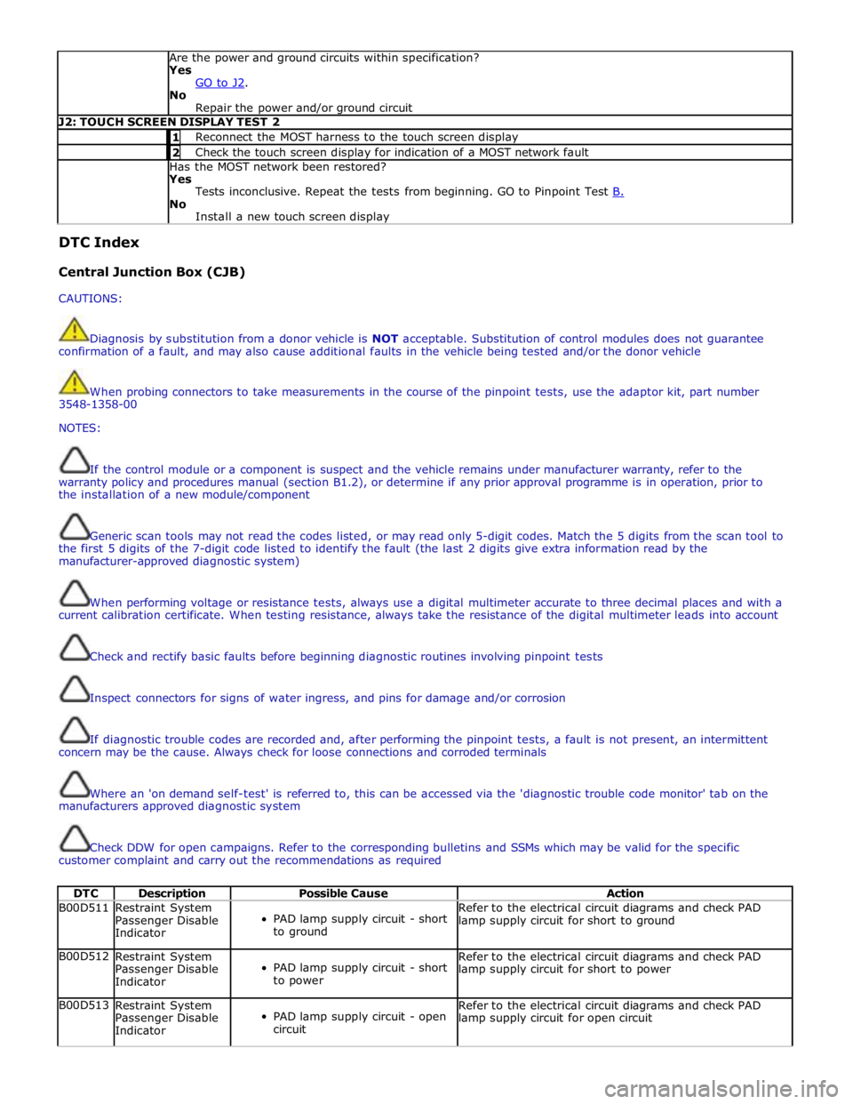
Are the power and ground circuits within specification?
Yes
GO to J2. No
Repair the power and/or ground circuit J2: TOUCH SCREEN DISPLAY TEST 2 1 Reconnect the MOST harness to the touch screen display 2 Check the touch screen display for indication of a MOST network fault Has the MOST network been restored?
Yes
Tests inconclusive. Repeat the tests from beginning. GO to Pinpoint Test B. No
Install a new touch screen display DTC Index
Central Junction Box (CJB)
CAUTIONS:
Diagnosis by substitution from a donor vehicle is NOT acceptable. Substitution of control modules does not guarantee
confirmation of a fault, and may also cause additional faults in the vehicle being tested and/or the donor vehicle
When probing connectors to take measurements in the course of the pinpoint tests, use the adaptor kit, part number
3548-1358-00
NOTES:
If the control module or a component is suspect and the vehicle remains under manufacturer warranty, refer to the
warranty policy and procedures manual (section B1.2), or determine if any prior approval programme is in operation, prior to
the installation of a new module/component
Generic scan tools may not read the codes listed, or may read only 5-digit codes. Match the 5 digits from the scan tool to
the first 5 digits of the 7-digit code listed to identify the fault (the last 2 digits give extra information read by the
manufacturer-approved diagnostic system)
When performing voltage or resistance tests, always use a digital multimeter accurate to three decimal places and with a
current calibration certificate. When testing resistance, always take the resistance of the digital multimeter leads into account
Check and rectify basic faults before beginning diagnostic routines involving pinpoint tests
Inspect connectors for signs of water ingress, and pins for damage and/or corrosion
If diagnostic trouble codes are recorded and, after performing the pinpoint tests, a fault is not present, an intermittent
concern may be the cause. Always check for loose connections and corroded terminals
Where an 'on demand self-test' is referred to, this can be accessed via the 'diagnostic trouble code monitor' tab on the
manufacturers approved diagnostic system
Check DDW for open campaigns. Refer to the corresponding bulletins and SSMs which may be valid for the specific
customer complaint and carry out the recommendations as required
DTC Description Possible Cause Action B00D511
Restraint System
Passenger Disable
Indicator
PAD lamp supply circuit - short
to ground Refer to the electrical circuit diagrams and check PAD
lamp supply circuit for short to ground B00D512
Restraint System
Passenger Disable
Indicator
PAD lamp supply circuit - short
to power Refer to the electrical circuit diagrams and check PAD
lamp supply circuit for short to power B00D513
Restraint System
Passenger Disable
Indicator
PAD lamp supply circuit - open
circuit Refer to the electrical circuit diagrams and check PAD
lamp supply circuit for open circuit