diagram JAGUAR XFR 2010 1.G Workshop Manual
[x] Cancel search | Manufacturer: JAGUAR, Model Year: 2010, Model line: XFR, Model: JAGUAR XFR 2010 1.GPages: 3039, PDF Size: 58.49 MB
Page 1962 of 3039

11
12
1
2
3
4
5
6
7
8
9
10
11
12
13LH rear tweet er speakerLH rear mi d-bass speaker
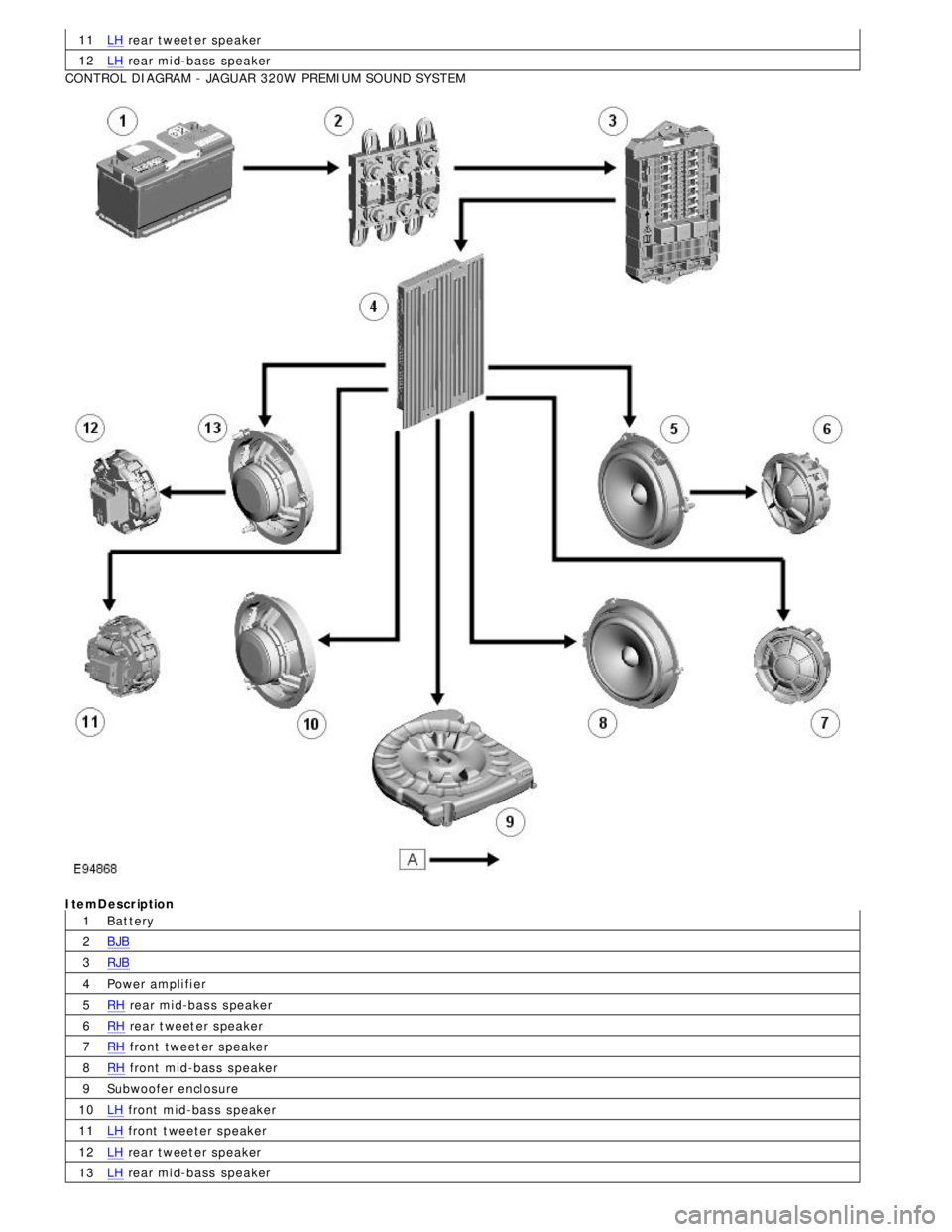
CONTROL DIAGRAM - JAGUAR 320W PREMIUM SOUND SY STEMItemDescription
Bat teryBJBRJB
Power ampli fi erRH rear mi d-bas s s peakerRH rear t weet er s peakerRH front tweet er s peakerRH front mid-bas s s peaker
Subwoofer encl osureLH front mid-bas s s peakerLH front t weeter s peakerLH rear tweet er speakerLH rear mi d-bass speaker
Page 1963 of 3039

1
2
3
4
5
6
7
8
9
10
11
12
13
14
15
16
17
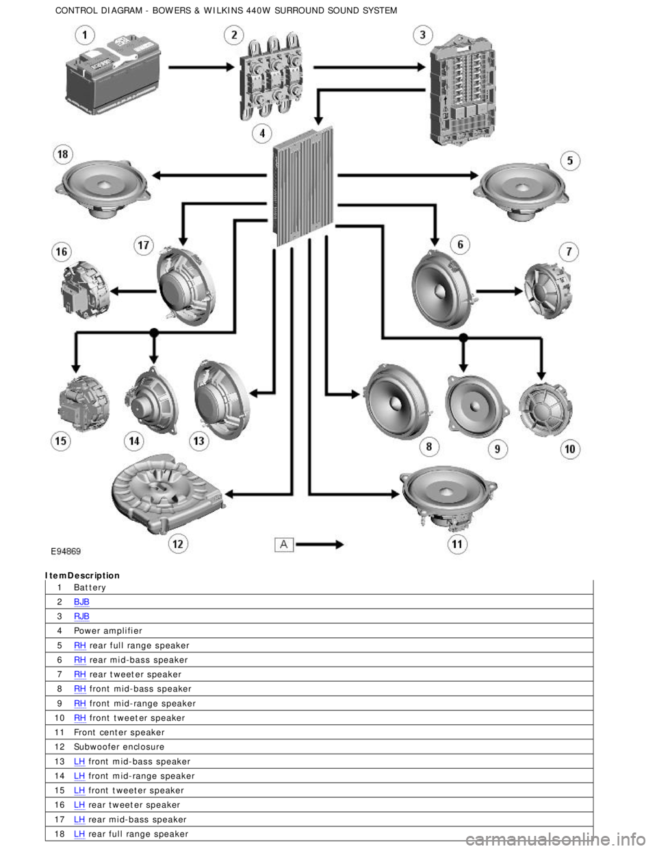
18ItemDescription
Bat teryBJBRJB
Power ampli fi erRH rear ful l range s peakerRH rear mi d-bas s s peakerRH rear t weet er s peakerRH front mid-bas s s peakerRH front mid-range s peakerRH front tweet er s peaker
Front center s peaker
Subwoofer encl osureLH front mid-bas s s peakerLH front mid-range s peakerLH front t weeter s peakerLH rear tweet er speakerLH rear mi d-bass speakerLH rear ful l range s peaker CONTROL DIAGRAM - BOW ERS & W ILKINS 440W SURROUND SOUND SY STEM
Page 1967 of 3039

1
2
3
4
5
6
7
8
9
10
11Publi s hed: 11-May-2011
Information and Entertainment System - Cellular Phone - System Operation
and Component Description
Des cript ion and Operat ion
Control Diagram
• NOTE: A = Hardwi red; N = Medium Speed CAN (controller area net work) bus ; O = LIN bus ; P = MOST ringItemDescription
Touch-s creen
Power ampli fi er
Speakers
IAM (i nt egrat ed audi o module)
Microphone
Tel ephone cont rol module
Cl ock spring
St eering wheel cont rol s
ICM (i nformat ion control modul e)
Ins trument cl us t er
Navigat ion computer
Page 1974 of 3039

Published: 11-May-2011
Information and Entertainment System - Navigation System - System
Operation and Component Description
Description and Operation
Control Diagram
NOTE: A = Hardwired; D = High Speed CAN bus; N = Medium Speed CAN bus; O = LIN bus; P = MOST ring; Q = GVIF; T
= CoAxial
Item Description 1 ABS (anti-lock brake system) module 2 Steering wheel remote audio controls 3 Touch-screen 4 Power amplifier 5 Speakers
Page 1985 of 3039

1
2
3
4
5
6
7
8
9
10Publi s hed: 11-May-2011
Information and Entertainment System - Video System - System Operation
and Component Description
Des cript ion and Operat ion
Control Diagram
• NOTE: A = Hardwi red; N = Medium Speed CAN (controller area net work) bus ; O = LIN bus ; P = MOST ring; T = CoAxial; I
= Compos it e video s i gnalItemDescription
Triple TV (televis i on) ant enna modul e
TV (t elevis ion) t uner
Touch-s creen
Microphone
IAM (i nt egrat ed audi o module)
Speakers
Power ampli fi er
Cl ock spring
St eering wheel remote controls
ICM (i nformat ion control modul e)11
12ICP (int egrated control panel)
Si ngl e TV (t el evi s ion) ant enna module
www.JagDocs.com
Page 2024 of 3039

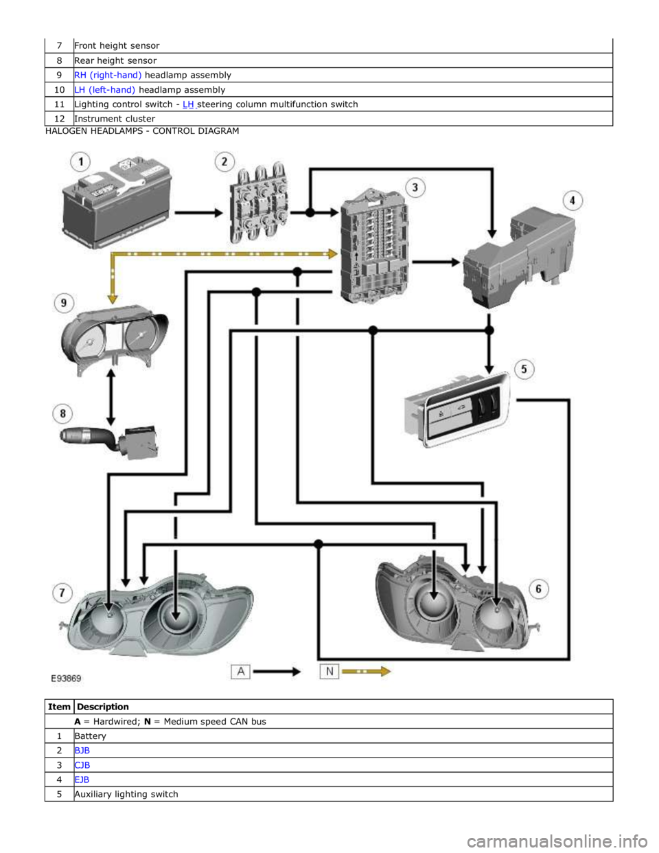
8 Rear height sensor 9 RH (right-hand) headlamp assembly 10 LH (left-hand) headlamp assembly 11 Lighting control switch - LH steering column multifunction switch 12 Instrument cluster HALOGEN HEADLAMPS - CONTROL DIAGRAM
Item Description A = Hardwired; N = Medium speed CAN bus 1 Battery 2 BJB 3 CJB 4 EJB 5 Auxiliary lighting switch
Page 2025 of 3039

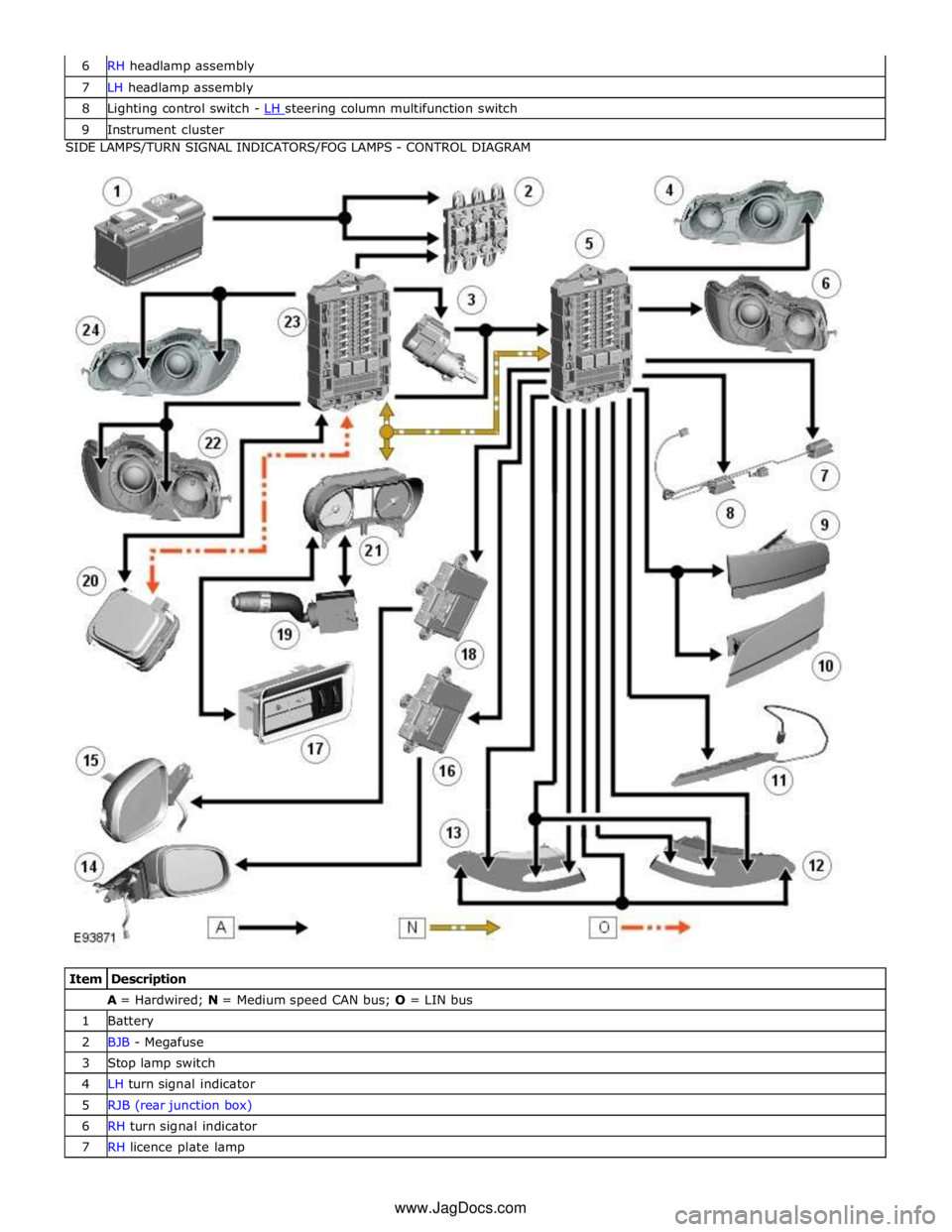
7 LH headlamp assembly 8 Lighting control switch - LH steering column multifunction switch 9 Instrument cluster SIDE LAMPS/TURN SIGNAL INDICATORS/FOG LAMPS - CONTROL DIAGRAM
Item Description A = Hardwired; N = Medium speed CAN bus; O = LIN bus 1 Battery 2 BJB - Megafuse 3 Stop lamp switch 4 LH turn signal indicator 5 RJB (rear junction box) 6 RH turn signal indicator 7 RH licence plate lamp www.JagDocs.com
Page 2057 of 3039

8 Passenger door module 9 LH (left-hand) rear door latch 10 RH (right-hand) rear door latch 11 LH front door latch 12 RH front door latch 13 CJB (central junction box) 14 LH front door handle LED (light emitting diode) illumination 15 RH front door handle LED illumination CONTROL DIAGRAM (SHEET 2 OF 2)
Item Description A = Hardwired 1 Battery 2 BJB - Megafuse
Page 2063 of 3039

Interior Lighting - Interior Lighting
Diagnosis and Testing
Principles of Operation Published: 11-May-2011
For a detailed description of the interior lighting system, refer to the relevant Description and Operation sections in the
workshop manual. REFER to: (417-02 Interior Lighting)
Interior Lighting (Description and Operation), Interior Lighting (Description and Operation), Interior Lighting (Description and Operation).
Inspection and Verification
CAUTION: Diagnosis by substitution from a donor vehicle is NOT acceptable. Substitution of control modules does not
guarantee confirmation of a fault, and may also cause additional faults in the vehicle being tested and/or the donor vehicle.
1. Verify the customer concern.
2. Visually inspect for obvious signs of damage and system integrity.
Visual Inspection
Mechanical Electrical
Bulbs
Fuses/relays (refer to electrical guide)
Wiring harness
Correct engagement of electrical connectors
Loose or corroded connections
3. If an obvious cause for an observed or reported concern is found, correct the cause (if possible) before proceeding to
the next step.
4. If the cause is not visually evident, check for Diagnostic Trouble Codes (DTCs) and refer to the DTC Index.
DTC Index
CAUTION: When probing connectors to take measurements in the course of the pinpoint tests, use the adaptor kit, part
number 3548-1358-00
NOTES:
If the control module or a component is suspect and the vehicle remains under manufacturer warranty, refer to the
Warranty Policy and Procedures manual (section B1.2), or determine if any prior approval programme is in operation, prior to
the installation of a new module/component.
Generic scan tools may not read the codes listed, or may read only five digit codes. Match the five digits from the scan
tool to the first five digits of the seven digit code listed to identify the fault (the last two digits give extra information read by
the manufacturer-approved diagnostic system).
When performing voltage or resistance tests, always use a digital multimeter (DMM) accurate to three decimal places and
with a current calibration certificate. When testing resistance, always take the resistance of the DMM leads into account.
Check and rectify basic faults before beginning diagnostic routines involving pinpoint tests.
If DTCs are recorded and, after performing the pinpoint tests, a fault is not present, an intermittent concern may be the
cause. Always check for loose connections and corroded terminals.
DTC Description Possible Cause Action B116511
Left Front
Puddle Lamp
Output
Left front puddle lamp
control circuit - short to
ground Refer to the electrical circuit diagrams and test left front puddle
lamp control circuit for short to ground
Page 2064 of 3039

DTC Description Possible Cause Action B116515
Left Front
Puddle Lamp
Output
Left front puddle lamp
control circuit - short to
power, open circuit Carry out any pinpoint tests associated with this DTC using the
manufacturer approved diagnostic system. Refer to the electrical
circuit diagrams and test left front puddle lamp control circuit
for short to power, open circuit B116611
Right Front
Puddle Lamp
Output
Right front puddle lamp
control circuit - short to
ground Refer to the electrical circuit diagrams and test right front
puddle lamp control circuit for short to ground B116615
Right Front
Puddle Lamp
Output
Right front puddle lamp
control circuit - short to
power, open circuit Carry out any pinpoint tests associated with this DTC using the
manufacturer approved diagnostic system. Refer to the electrical
circuit diagrams and test right front puddle lamp control circuit
for short to power, open circuit B111E11
Boot/Trunk
Lamps
Luggage compartment lamp
control circuit - short to
ground Carry out any pinpoint test associated with this DTC using the
manufacturer approved diagnostic system. Refer to the electrical
circuit diagrams and check luggage compartment lamp control
circuit for short to ground B111E15
Boot/Trunk
Lamps
Luggage compartment lamp
control circuit - short to
power, open circuit Carry out any pinpoint test associated with this DTC using the
manufacturer approved diagnostic system. Refer to the electrical
circuit diagrams and check luggage compartment lamp control
circuit for short to power, open circuit B112412
Lamp Fade
Control
Interior lamp fade control
circuit - short to power Refer to the electrical circuit diagrams and check interior lamp
fade control circuit for short to power B113C12
Hazard Switch
Illumination
Hazard switch illumination
control circuit - short to
power Refer to the electrical circuit diagrams and check hazard switch
illumination control circuit for short to power B1A8596
Ambient Light
Sensor
Light sensor internal
electronic failure Check and install a new sensor as required U201012
Switch
Illumination
Switch/interior illumination
PWM supply circuit - short to
power Refer to the electrical circuit diagrams and check switch/interior
illumination PWM supply circuit for short to power U201014
Switch
Illumination
Switch/interior illumination
PWM supply circuit - short to
ground, open circuit Refer to the electrical circuit diagrams and check switch/interior
illumination PWM supply circuit for short to ground, open circuit