battery monitoring module JAGUAR XFR 2010 1.G Owner's Manual
[x] Cancel search | Manufacturer: JAGUAR, Model Year: 2010, Model line: XFR, Model: JAGUAR XFR 2010 1.GPages: 3039, PDF Size: 58.49 MB
Page 460 of 3039
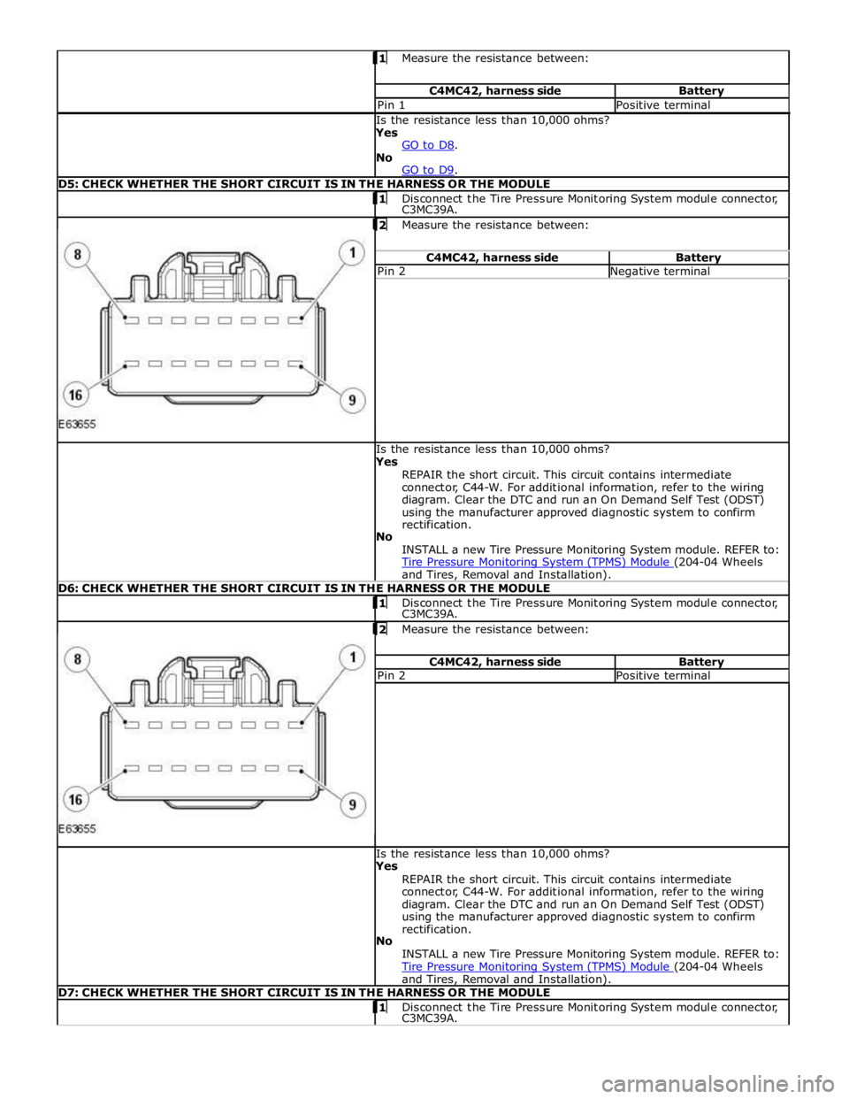
Measure the resistance between: C4MC42, harness side Battery Pin 1 Positive terminal Is the resistance less than 10,000 ohms?
Yes
GO to D8. No
GO to D9. D5: CHECK WHETHER THE SHORT CIRCUIT IS IN THE HARNESS OR THE MODULE 1 Disconnect the Tire Pressure Monitoring System module connector, C3MC39A.
2 Measure the resistance between: C4MC42, harness side Battery Pin 2 Negative terminal Is the resistance less than 10,000 ohms?
Yes
REPAIR the short circuit. This circuit contains intermediate
connector, C44-W. For additional information, refer to the wiring
diagram. Clear the DTC and run an On Demand Self Test (ODST)
using the manufacturer approved diagnostic system to confirm
rectification.
No
INSTALL a new Tire Pressure Monitoring System module. REFER to:
Tire Pressure Monitoring System (TPMS) Module (204-04 Wheels and Tires, Removal and Installation). D6: CHECK WHETHER THE SHORT CIRCUIT IS IN THE HARNESS OR THE MODULE 1 Disconnect the Tire Pressure Monitoring System module connector, C3MC39A. 2 Measure the resistance between: C4MC42, harness side Battery Pin 2 Positive terminal Is the resistance less than 10,000 ohms?
Yes
REPAIR the short circuit. This circuit contains intermediate
connector, C44-W. For additional information, refer to the wiring
diagram. Clear the DTC and run an On Demand Self Test (ODST)
using the manufacturer approved diagnostic system to confirm
rectification.
No
INSTALL a new Tire Pressure Monitoring System module. REFER to:
Tire Pressure Monitoring System (TPMS) Module (204-04 Wheels and Tires, Removal and Installation). D7: CHECK WHETHER THE SHORT CIRCUIT IS IN THE HARNESS OR THE MODULE 1 Disconnect the Tire Pressure Monitoring System module connector, C3MC39A.
Page 461 of 3039
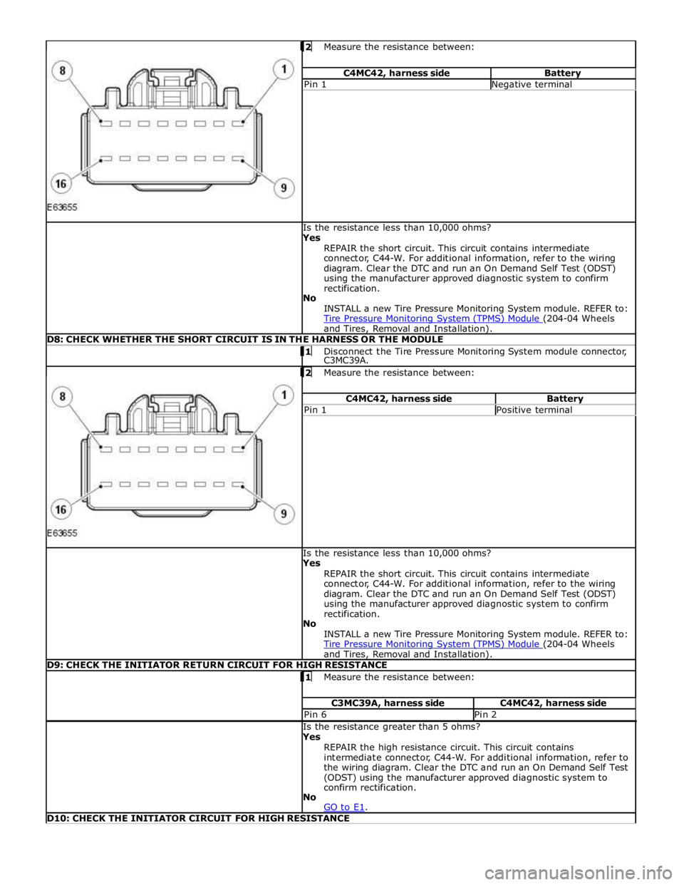
Measure the resistance between: C4MC42, harness side Battery Pin 1 Negative terminal Is the resistance less than 10,000 ohms?
Yes
REPAIR the short circuit. This circuit contains intermediate
connector, C44-W. For additional information, refer to the wiring
diagram. Clear the DTC and run an On Demand Self Test (ODST)
using the manufacturer approved diagnostic system to confirm
rectification.
No
INSTALL a new Tire Pressure Monitoring System module. REFER to:
Tire Pressure Monitoring System (TPMS) Module (204-04 Wheels and Tires, Removal and Installation). D8: CHECK WHETHER THE SHORT CIRCUIT IS IN THE HARNESS OR THE MODULE 1 Disconnect the Tire Pressure Monitoring System module connector, C3MC39A.
2 Measure the resistance between: C4MC42, harness side Battery Pin 1 Positive terminal Is the resistance less than 10,000 ohms?
Yes
REPAIR the short circuit. This circuit contains intermediate
connector, C44-W. For additional information, refer to the wiring
diagram. Clear the DTC and run an On Demand Self Test (ODST)
using the manufacturer approved diagnostic system to confirm
rectification.
No
INSTALL a new Tire Pressure Monitoring System module. REFER to:
Tire Pressure Monitoring System (TPMS) Module (204-04 Wheels and Tires, Removal and Installation). D9: CHECK THE INITIATOR RETURN CIRCUIT FOR HIGH RESISTANCE 1 Measure the resistance between: C3MC39A, harness side C4MC42, harness side Pin 6 Pin 2 Is the resistance greater than 5 ohms?
Yes
REPAIR the high resistance circuit. This circuit contains
intermediate connector, C44-W. For additional information, refer to
the wiring diagram. Clear the DTC and run an On Demand Self Test
(ODST) using the manufacturer approved diagnostic system to
confirm rectification.
No
GO to E1. D10: CHECK THE INITIATOR CIRCUIT FOR HIGH RESISTANCE
Page 463 of 3039
No
GO to E9. E5: CHECK WHETHER THE SHORT CIRCUIT IS IN THE HARNESS OR THE MODULE 1 Disconnect the Tire Pressure Monitoring System module connector, C3MC39A.
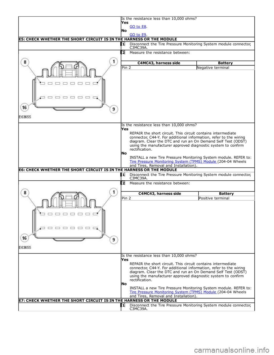
2 Measure the resistance between: C4MC43, harness side Battery Pin 2 Negative terminal Is the resistance less than 10,000 ohms?
Yes
REPAIR the short circuit. This circuit contains intermediate
connector, C44-Y. For additional information, refer to the wiring
diagram. Clear the DTC and run an On Demand Self Test (ODST)
using the manufacturer approved diagnostic system to confirm
rectification.
No
INSTALL a new Tire Pressure Monitoring System module. REFER to:
Tire Pressure Monitoring System (TPMS) Module (204-04 Wheels and Tires, Removal and Installation). E6: CHECK WHETHER THE SHORT CIRCUIT IS IN THE HARNESS OR THE MODULE 1 Disconnect the Tire Pressure Monitoring System module connector, C3MC39A.
2 Measure the resistance between: C4MC43, harness side Battery Pin 2 Positive terminal Is the resistance less than 10,000 ohms?
Yes
REPAIR the short circuit. This circuit contains intermediate
connector, C44-Y. For additional information, refer to the wiring
diagram. Clear the DTC and run an On Demand Self Test (ODST)
using the manufacturer approved diagnostic system to confirm
rectification.
No
INSTALL a new Tire Pressure Monitoring System module. REFER to:
Tire Pressure Monitoring System (TPMS) Module (204-04 Wheels and Tires, Removal and Installation). E7: CHECK WHETHER THE SHORT CIRCUIT IS IN THE HARNESS OR THE MODULE 1 Disconnect the Tire Pressure Monitoring System module connector, C3MC39A.
Page 464 of 3039
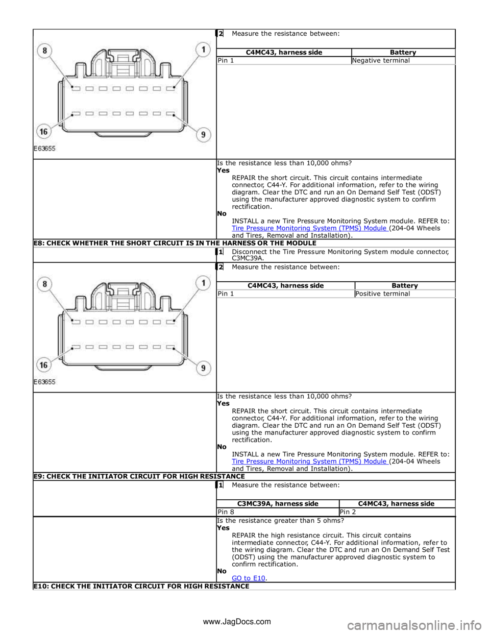
Measure the resistance between: C4MC43, harness side Battery Pin 1 Negative terminal Is the resistance less than 10,000 ohms?
Yes
REPAIR the short circuit. This circuit contains intermediate
connector, C44-Y. For additional information, refer to the wiring
diagram. Clear the DTC and run an On Demand Self Test (ODST)
using the manufacturer approved diagnostic system to confirm
rectification.
No
INSTALL a new Tire Pressure Monitoring System module. REFER to:
Tire Pressure Monitoring System (TPMS) Module (204-04 Wheels and Tires, Removal and Installation). E8: CHECK WHETHER THE SHORT CIRCUIT IS IN THE HARNESS OR THE MODULE 1 Disconnect the Tire Pressure Monitoring System module connector, C3MC39A.
2 Measure the resistance between: C4MC43, harness side Battery Pin 1 Positive terminal Is the resistance less than 10,000 ohms?
Yes
REPAIR the short circuit. This circuit contains intermediate
connector, C44-Y. For additional information, refer to the wiring
diagram. Clear the DTC and run an On Demand Self Test (ODST)
using the manufacturer approved diagnostic system to confirm
rectification.
No
INSTALL a new Tire Pressure Monitoring System module. REFER to:
Tire Pressure Monitoring System (TPMS) Module (204-04 Wheels and Tires, Removal and Installation). E9: CHECK THE INITIATOR CIRCUIT FOR HIGH RESISTANCE 1 Measure the resistance between: C3MC39A, harness side C4MC43, harness side Pin 8 Pin 2 Is the resistance greater than 5 ohms?
Yes
REPAIR the high resistance circuit. This circuit contains
intermediate connector, C44-Y. For additional information, refer to
the wiring diagram. Clear the DTC and run an On Demand Self Test
(ODST) using the manufacturer approved diagnostic system to
confirm rectification.
No
GO to E10. E10: CHECK THE INITIATOR CIRCUIT FOR HIGH RESISTANCE www.JagDocs.com
Page 467 of 3039
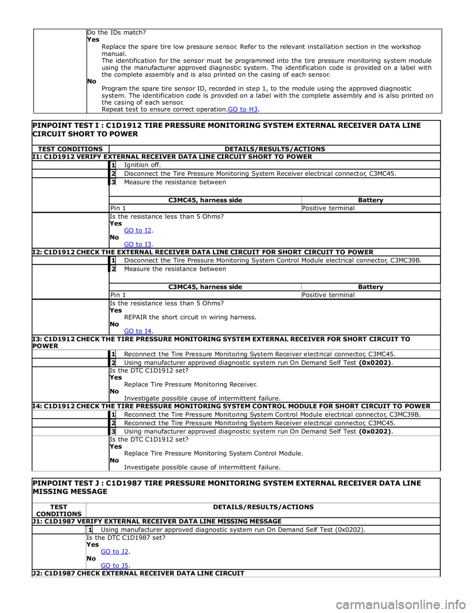
TEST CONDITIONS DETAILS/RESULTS/ACTIONS I1: C1D1912 VERIFY EXTERNAL RECEIVER DATA LINE CIRCUIT SHORT TO POWER 1 Ignition off. 2 Disconnect the Tire Pressure Monitoring System Receiver electrical connector, C3MC45. 3 Measure the resistance between C3MC45, harness side Battery Pin 1 Positive terminal Is the resistance less than 5 Ohms?
Yes
GO to I2. No
GO to I3. I2: C1D1912 CHECK THE EXTERNAL RECEIVER DATA LINE CIRCUIT FOR SHORT CIRCUIT TO POWER 1 Disconnect the Tire Pressure Monitoring System Control Module electrical connector, C3MC39B. 2 Measure the resistance between C3MC45, harness side Battery Pin 1 Positive terminal Is the resistance less than 5 Ohms?
Yes
REPAIR the short circuit in wiring harness.
No
GO to I4. I3: C1D1912 CHECK THE TIRE PRESSURE MONITORING SYSTEM EXTERNAL RECEIVER FOR SHORT CIRCUIT TO
POWER 1 Reconnect the Tire Pressure Monitoring System Receiver electrical connector, C3MC45. 2 Using manufacturer approved diagnostic system run On Demand Self Test (0x0202). Is the DTC C1D1912 set?
Yes
Replace Tire Pressure Monitoring Receiver.
No
Investigate possible cause of intermittent failure. I4: C1D1912 CHECK THE TIRE PRESSURE MONITORING SYSTEM CONTROL MODULE FOR SHORT CIRCUIT TO POWER 1 Reconnect the Tire Pressure Monitoring System Control Module electrical connector, C3MC39B. 2 Reconnect the Tire Pressure Monitoring System Receiver electrical connector, C3MC45. 3 Using manufacturer approved diagnostic system run On Demand Self Test (0x0202). Is the DTC C1D1912 set?
Yes
Replace Tire Pressure Monitoring System Control Module.
No
Investigate possible cause of intermittent failure.
PINPOINT TEST J : C1D1987 TIRE PRESSURE MONITORING SYSTEM EXTERNAL RECEIVER DATA LINE
MISSING MESSAGE TEST
CONDITIONS DETAILS/RESULTS/ACTIONS J1: C1D1987 VERIFY EXTERNAL RECEIVER DATA LINE MISSING MESSAGE 1 Using manufacturer approved diagnostic system run On Demand Self Test (0x0202). Is the DTC C1D1987 set? Yes
GO to J2. No
GO to J5. J2: C1D1987 CHECK EXTERNAL RECEIVER DATA LINE CIRCUIT Do the IDs match?
Yes
Replace the spare tire low pressure sensor. Refer to the relevant installation section in the workshop
manual.
The identification for the sensor must be programmed into the tire pressure monitoring system module
using the manufacturer approved diagnostic system. The identification code is provided on a label with
the complete assembly and is also printed on the casing of each sensor.
No
Program the spare tire sensor ID, recorded in step 1, to the module using the approved diagnostic
system. The identification code is provided on a label with the complete assembly and is also printed on
the casing of each sensor.
Repeat test to ensure correct operation.GO to H3.
Page 1344 of 3039
Published: 11-May-2011
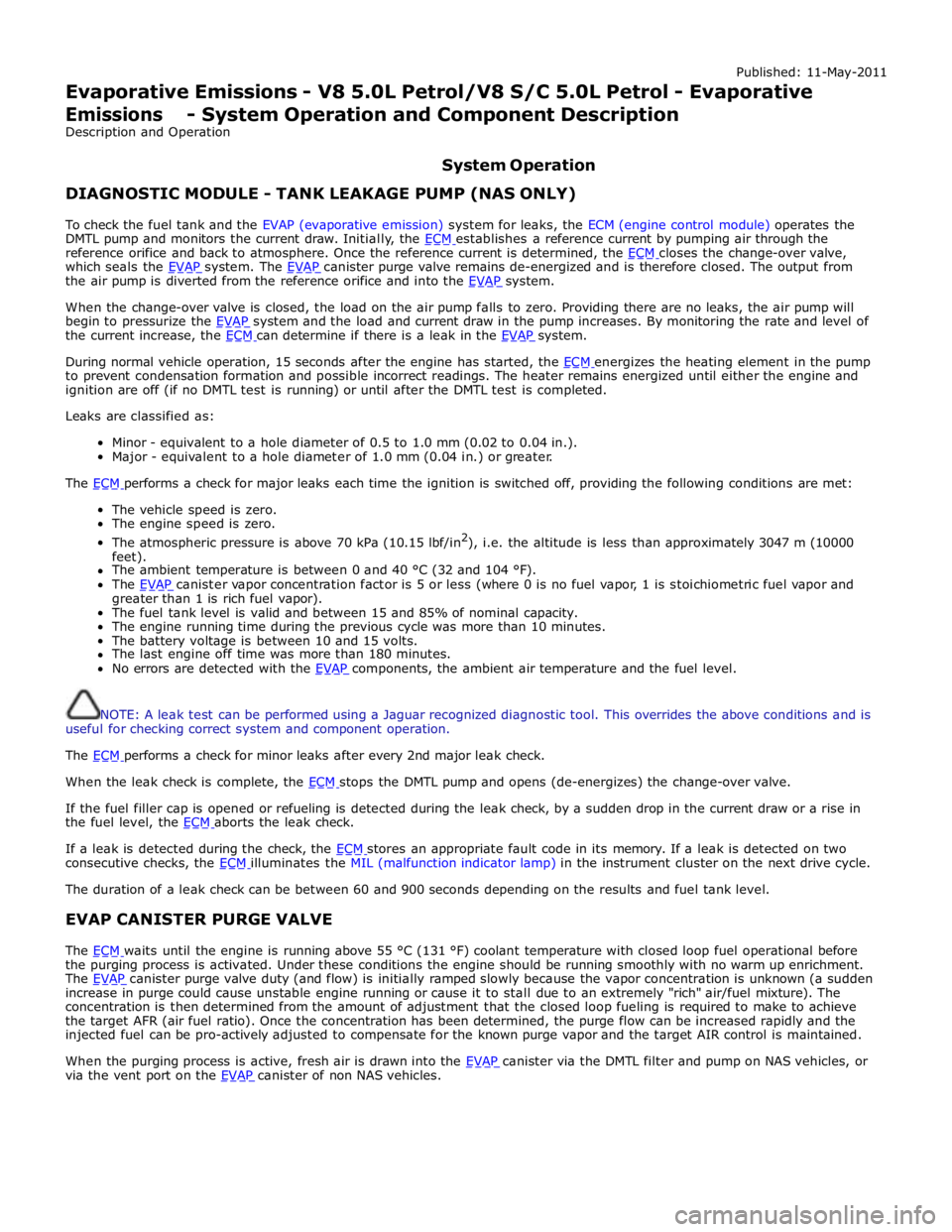
Evaporative Emissions - V8 5.0L Petrol/V8 S/C 5.0L Petrol - Evaporative Emissions - System Operation and Component Description
Description and Operation
System Operation DIAGNOSTIC MODULE - TANK LEAKAGE PUMP (NAS ONLY)
To check the fuel tank and the EVAP (evaporative emission) system for leaks, the ECM (engine control module) operates the
DMTL pump and monitors the current draw. Initially, the ECM establishes a reference current by pumping air through the reference orifice and back to atmosphere. Once the reference current is determined, the ECM closes the change-over valve, which seals the EVAP system. The EVAP canister purge valve remains de-energized and is therefore closed. The output from the air pump is diverted from the reference orifice and into the EVAP system.
When the change-over valve is closed, the load on the air pump falls to zero. Providing there are no leaks, the air pump will
begin to pressurize the EVAP system and the load and current draw in the pump increases. By monitoring the rate and level of the current increase, the ECM can determine if there is a leak in the EVAP system.
During normal vehicle operation, 15 seconds after the engine has started, the ECM energizes the heating element in the pump to prevent condensation formation and possible incorrect readings. The heater remains energized until either the engine and
ignition are off (if no DMTL test is running) or until after the DMTL test is completed.
Leaks are classified as:
Minor - equivalent to a hole diameter of 0.5 to 1.0 mm (0.02 to 0.04 in.).
Major - equivalent to a hole diameter of 1.0 mm (0.04 in.) or greater.
The ECM performs a check for major leaks each time the ignition is switched off, providing the following conditions are met: The vehicle speed is zero.
The engine speed is zero.
The atmospheric pressure is above 70 kPa (10.15 lbf/in2
), i.e. the altitude is less than approximately 3047 m (10000
feet).
The ambient temperature is between 0 and 40 °C (32 and 104 °F).
The EVAP canister vapor concentration factor is 5 or less (where 0 is no fuel vapor, 1 is stoichiometric fuel vapor and greater than 1 is rich fuel vapor).
The fuel tank level is valid and between 15 and 85% of nominal capacity.
The engine running time during the previous cycle was more than 10 minutes.
The battery voltage is between 10 and 15 volts.
The last engine off time was more than 180 minutes.
No errors are detected with the EVAP components, the ambient air temperature and the fuel level.
NOTE: A leak test can be performed using a Jaguar recognized diagnostic tool. This overrides the above conditions and is
useful for checking correct system and component operation.
The ECM performs a check for minor leaks after every 2nd major leak check.
When the leak check is complete, the ECM stops the DMTL pump and opens (de-energizes) the change-over valve.
If the fuel filler cap is opened or refueling is detected during the leak check, by a sudden drop in the current draw or a rise in
the fuel level, the ECM aborts the leak check.
If a leak is detected during the check, the ECM stores an appropriate fault code in its memory. If a leak is detected on two consecutive checks, the ECM illuminates the MIL (malfunction indicator lamp) in the instrument cluster on the next drive cycle. The duration of a leak check can be between 60 and 900 seconds depending on the results and fuel tank level.
EVAP CANISTER PURGE VALVE
The ECM waits until the engine is running above 55 °C (131 °F) coolant temperature with closed loop fuel operational before the purging process is activated. Under these conditions the engine should be running smoothly with no warm up enrichment.
The EVAP canister purge valve duty (and flow) is initially ramped slowly because the vapor concentration is unknown (a sudden increase in purge could cause unstable engine running or cause it to stall due to an extremely "rich" air/fuel mixture). The
concentration is then determined from the amount of adjustment that the closed loop fueling is required to make to achieve
the target AFR (air fuel ratio). Once the concentration has been determined, the purge flow can be increased rapidly and the
injected fuel can be pro-actively adjusted to compensate for the known purge vapor and the target AIR control is maintained.
When the purging process is active, fresh air is drawn into the EVAP canister via the DMTL filter and pump on NAS vehicles, or via the vent port on the EVAP canister of non NAS vehicles.
Page 1373 of 3039

DTC Description Possible Causes Action B10AC-81
Cruise Control Switch -
invalid serial data received
The Engine Control Module
(ECM) has received an invalid
command from the steering
wheel switch pack Clear the DTC and press all the steering wheel
switches, re-check for DTCs. Refer to the
electrical circuit diagrams and check the Cruise
control switch circuit for open circuit, short to
power, short to ground, disconnected. Check
and install a new Steering Wheel Module (SWM) as required. B10AC-82 Cruise Control Switch - alive / sequence counter incorrect / not updated
Cruise Buttons alive counter is
not incrementing. Which
suggests that the LIN bus is
faulty
Steering Wheel Module (SWM) is
not connected
Steering Wheel Module (SWM)
failure Refer to the electrical circuit diagrams and
check the Cruise control switch circuit for open
circuit, short to power, short to ground,
disconnected. Check and install a new Steering
Wheel Module (SWM) as required. B10AC-83
Cruise Control Switch - value
of signal protection
calculation incorrect
Cruise buttons checksum
incorrect, incorrect cruise
switches fitted to vehicle Check and install new cruise switches as
required. B10AC-96
Cruise Control Switch -
component internal failure
Cruise control switch circuit,
open circuit, short to power,
short to ground, disconnected
Cruise Control Switch failure
Steering Wheel Module (SWM)
failure Check for related DTCs in other Central
Junction Box (CJB)s. Refer to the electrical
circuit diagrams and check the Cruise control
switch circuit for open circuit, short to power,
short to ground, disconnected. Check and
install a new cruise control switch as required.
Check and install a new Steering Wheel
Module (SWM) as required. B10FF-68
Ignition Control - Event
information
Spark plug(s) fault
Wiring harness fault
Ignition coil(s) fault Refer to repair manual and check spark plug(s)
for condition and security. Replace any
defective components as required. Refer to
electrical wiring diagrams and check ignition
coil circuit for intermittent open circuit, short
to power, short to ground. Check and install a
new coil(s) as required. B11DB-01
Battery Monitoring Module -
General Electrical Failure
Charging system fault Battery
monitoring signal line
circuit fault
Vehicle battery fault Refer to electrical wiring diagrams and check
charging system for faults. Perform any repairs
required. Refer to the electrical wiring
diagrams and check the Battery Monitoring
System (BMS) module circuit for open circuit,
short to ground, short to power. Refer to the
battery care manual and check and install a
new battery. B11DB-87
Battery Monitoring Module -
missing message
Battery signal line circuit fault Refer to the electrical wiring diagrams and
check the Battery Monitoring System (BMS)
module circuit for open circuit, short to ground,
short to power. B1206-68
Crash Occurred - event
information
Engine control Module (ECM) has
detected the vehicle has crashed
- event information DTC only Refer to the electrical circuit diagrams and
check the Engine Control Module (ECM) to
Restraints Control Module (RCM) circuit for
short to ground, short to power, open circuit.
Repair circuit as required, clear DTC and retest
system to confirm repair. C0031-00
Left Front Wheel Speed
Sensor - No sub type
information
Invalid data received from
Anti-lock Braking System (ABS)
module - left front wheel speed
signal fault Check Anti-lock Braking System (ABS) module
for related DTCs and refer to relevant DTC
Index. C0034-00
Right Front Wheel Speed
Sensor - No sub type
information
Invalid data received from
Anti-lock Braking System (ABS)
module - right front wheel speed
signal fault Check Anti-lock Braking System (ABS) module
for related DTCs and refer to relevant DTC
Index. C0037-00
Left Rear Wheel Speed
Sensor - No sub type
information
Invalid data received from
Anti-lock Braking System (ABS)
module - left rear wheel speed
signal fault Check Anti-lock Braking System (ABS) module
for related DTCs and refer to relevant DTC
Index. C003A-00
Right Rear Wheel Speed
Sensor - No sub type
information
Invalid data received from
Anti-lock Braking System (ABS)
module - right rear wheel speed
signal fault Check Anti-lock Braking System (ABS) module
for related DTCs and refer to relevant DTC
Index.
Page 1438 of 3039

DTC Description Possible Cause Action P061B-02
Internal Control Module Torque Calculation
Performance - general signal
failure
Transmission control
module - positive torque
signal not valid Suspect the Transmission control module. Install a
new Transmission control module as required, refer to
the new module/component installation note at the
top of the DTC Index P061B-26
Internal Control Module Torque Calculation
Performance - signal rate of
change below threshold
Transmission control
module positive torque
signal not valid Suspect the Transmission control module. Install a
new Transmission control module as required, refer to
the new module/component installation note at the
top of the DTC Index P062F-04
Internal Control Module
EEPROM Error - System
Internal Failures
EEPROM communication
error Suspect the Transmission control module. Install a
new Transmission control module as required, refer to
the new module/component installation note at the top of the DTC Index P0642-21
Sensor Reference Voltage A
Circuit Low - signal
amplitude < minimum
Sensor supply voltage
fault low Suspect the Transmission control module. Install a
new Transmission control module as required, refer to
the new module/component installation note at the top of the DTC Index P0643-22
Sensor Reference Voltage A
Circuit High - signal
amplitude > maximum
Sensor supply voltage
fault high Suspect the Transmission control module. Install a
new Transmission control module as required, refer to
the new module/component installation note at the top of the DTC Index P0657-13
Actuator Supply Voltage A
Circuit / Open - Circuit Open
Actuator supply (pressure
control valves etc) Open
Circuit Suspect the Transmission control module. Install a
new Transmission control module as required, refer to
the new module/component installation note at the
top of the DTC Index P0657-1C
Actuator Supply Voltage A
Circuit / Open - Circuit
voltage out of range
Actuator supply (pressure
control valves etc)
voltage plausibility fault Refer to electrical Circuit diagrams and check
Transmission control module connector for signs of
water ingress or damage, check pin 7 for Short to
Power or Ground (should NOT be connected and
harness terminal should have a bung fitted). If no
fault identified, suspect the Transmission control
module. Check and install a new Transmission control
module as required, refer to the new
module/component installation note at the top of the
DTC Index P0658-11
Actuator Supply Voltage A
Circuit Low - Circuit Short to
Ground
Actuator supply (pressure
control valves etc)
voltage Short to Ground Suspect the Transmission control module. Install a
new Transmission control module as required, refer to
the new module/component installation note at the
top of the DTC Index P0659-12
Actuator Supply Voltage A
Circuit High - Circuit Short to
Battery
Actuator supply (pressure
control valves etc)
voltage Short to Power Suspect the Transmission control module. Install a
new Transmission control module as required, refer to
the new module/component installation note at the
top of the DTC Index P0667-01 PCM / Engine control module / Transmission control
module Internal Temperature
Sensor A Range/Performance
- General Electrical Failure
General electrical failure Suspect the Transmission control module. Install a
new Transmission control module as required, refer to
the new module/component installation note at the
top of the DTC Index P0667-04 PCM / Engine control module / Transmission control
module Internal Temperature
Sensor A Range/Performance
- System Internal Failures
Internal Electronic Failure Suspect the Transmission control module. Install a
new Transmission control module as required, refer to
the new module/component installation note at the
top of the DTC Index P0667-49 PCM / Engine control module / Transmission control
module Internal Temperature
Sensor A Range/Performance
- internal electronic failure
Internal electronic failure Suspect the Transmission control module. Install a
new Transmission control module as required, refer to
the new module/component installation note at the
top of the DTC Index P0700-02 Transmission Control System
(MIL Request) - General signal failure
General Signal failure Clear DTC, Road test and re-test, Read DTCs and
Investigate as required P0700-22 Transmission Control System
(MIL Request) - signal
amplitude > maximum
Double fault from
monitoring of internal
power supply and
pressure
regulator/solenoid
control software If any of the following DTCs are also present;
P074013, P096712, P273912, P273012, P272112,
P096312, P276312, P097112, suspect the Transmission
control module, check and install a new Transmission
control module as required, refer to the new
module/component installation note at the top of the
DTC Index P0700-75 Transmission Control System
(MIL Request) - Emergency
Position Not Reachable
Emergency Position Not
Reachable Clear DTC, Road test and re-test, Read DTCs and
investigate as required
Page 1440 of 3039

DTC Description Possible Cause Action P0721-64
Output Shaft Speed Sensor
Circuit Range/Performance -
signal plausibility failure
Signal plausibility failure Clear DTC and test. If code re-detects suspect the
Transmission control module. Install a new
Transmission control module as required, refer to the
new module/component installation note at the top of
the DTC Index P0731-07
Incorrect Gear Ratio-
Mechanical Failures
Gear Ratio Monitoring.
Mechanical Failures Check and correct oil level. Clear DTC. If code
re-detects suspect Transmission (gearbox) internal
fault. Install a new Transmission as required, refer to
the new module/component installation note at the top of the DTC Index P0732-07
Incorrect Gear Ratio-
Mechanical Failures
Gear Ratio Monitoring.
Mechanical Failures Check and correct oil level. Clear DTC. If code
re-detects suspect Transmission (gearbox) internal
fault. Install a new Transmission as required, refer to
the new module/component installation note at the top of the DTC Index P0733-07
Incorrect Gear Ratio-
Mechanical Failures
Gear Ratio Monitoring.
Mechanical Failures Check and correct oil level. Clear DTC. If code
re-detects suspect Transmission (gearbox) internal
fault. Install a new Transmission as required, refer to
the new module/component installation note at the top of the DTC Index P0734-07
Incorrect Gear Ratio-
Mechanical Failures
Gear Ratio Monitoring.
Mechanical Failures Check and correct oil level. Clear DTC. If code
re-detects suspect Transmission (gearbox) internal
fault. Install a new Transmission as required, refer to
the new module/component installation note at the top of the DTC Index P0735-07
Incorrect Gear Ratio-
Mechanical Failures
Gear Ratio Monitoring.
Mechanical Failures Check and correct oil level. Clear DTC. If code
re-detects suspect Transmission (gearbox) internal
fault. Install a new Transmission as required, refer to
the new module/component installation note at the top of the DTC Index P0736-07
Incorrect Gear Ratio-
Mechanical Failures
Gear Ratio Monitoring.
Mechanical Failures Check and correct oil level. Clear DTC. If code
re-detects suspect Transmission (gearbox) internal
fault. Install a new Transmission as required, refer to
the new module/component installation note at the top of the DTC Index P0740-13 Torque Converter Clutch
Solenoid Circuit / Open -
Circuit Open
Pressure control solenoid
2 Circuit Open Circuit Clear DTC and test. If code re-detects suspect the
Transmission control module. Install a new
Transmission control module as required, refer to the
new module/component installation note at the top of
the DTC Index P0741-07 Torque Converter Clutch
Solenoid Circuit
Performance/Stuck Off -
Mechanical Failures
Too high slip at torque
converter clutch.
Mechanical Failures Suspect torque converter lockup clutch. Install a new
torque converter, refer to the new module/component
installation note at the top of the DTC Index. If
transmission fluid is in very poor condition and dirty,
install a new transmission, refer to the new
module/component installation note at the top of the
DTC Index P0745-04 Pressure Control Solenoid A
- System Internal Failures
System Internal Failures Suspect the Transmission control module. Install a
new Transmission control module as required, refer to
the new module/component installation note at the top of the DTC Index P0745-48 Pressure Control Solenoid A
- Supervision Software
Failure
Supervision Software
Failure Suspect the Transmission control module. Install a
new Transmission control module as required, refer to
the new module/component installation note at the top of the DTC Index P0758-12
Shift Solenoid B Electrical -
Circuit Short to Battery
Circuit Short to Power Suspect the Transmission control module. Install a
new Transmission control module as required, refer to
the new module/component installation note at the top of the DTC Index P0758-13
Shift Solenoid B Electrical -
Circuit Open
Solenoid valve 1 or
Pressure control Solenoid
G Circuit Open Circuit Suspect the Transmission control module. Install a
new Transmission control module as required, refer to
the new module/component installation note at the
top of the DTC Index P0771-71
Shift Solenoid E
Performance/Stuck Off -
actuator stuck
Actuator stuck Suspect the Transmission control module. Install a
new Transmission control module as required, refer to
the new module/component installation note at the top of the DTC Index P0775-04 Pressure Control Solenoid B
- System Internal Failures
System Internal Failures Suspect the Transmission control module. Install a
new Transmission control module as required, refer to
the new module/component installation note at the top of the DTC Index P0775-48 Pressure Control Solenoid B
- Supervision Software
Failure
Supervision Software
Failure Suspect the Transmission control module. Install a
new Transmission control module as required, refer to
the new module/component installation note at the top of the DTC Index
Page 1442 of 3039

DTC Description Possible Cause Action P0829-07
5-6 Shift - Mechanical
Failures
Gear Ratio Monitoring.
Mechanical Failures Check and correct oil level. Clear DTC. If code
re-detects suspect Transmission internal fault. Install
a new Transmission as required, refer to the new
module/component installation note at the top of the
DTC Index P0829-77
6-5 Shift - Commanded
Position Not Reachable
Gear Ratio Monitoring.
Mechanical Failures Check and correct oil level. Clear DTC. If code
re-detects suspect Transmission internal fault. Install
a new Transmission as required, refer to the new
module/component installation note at the top of the
DTC Index P084F-01
Park / Neutral Switch Input
Circuit - General Electrical
Failure
Wrong voltage level
detected on Park/No Park
signal Check for correct output at Transmission control
module park signal pin (check in all positions) 12 volts
in Park, 0 volts in all other positions. If fault
identified, suspect the Transmission control module.
Install a new Transmission control module as required,
refer to the new module/component installation note
at the top of the DTC Index. If no fault identified,
check Park signal circuit to Transmission Shift Module
for short, open circuit. P0850-01
Park / Neutral Switch Input
Circuit - General Electrical
Failure
General electrical failure Suspect the Transmission control module. Install a
new Transmission control module as required, refer to
the new module/component installation note at the top of the DTC Index P0850-02
Park / Neutral Switch Input
Circuit - General signal
failure
General signal failure Check park lock mechanism. If park lock operation is
correct, suspect the transmission control module.
Check and install a new transmission control module
as required. Refer to the warranty policy and
procedures manual, or determine if any prior approval
programme is in operation, prior to the installation of
a new module/component P0850-29
Park / Neutral Switch Input
Circuit - signal invalid
Signal invalid Check park lock mechanism. If park lock operation is
correct, suspect the transmission control module.
Check and install a new transmission control module
as required. Refer to the warranty policy and
procedures manual, or determine if any prior approval
programme is in operation, prior to the installation of
a new module/component P850-1C
Park / Neutral Switch Input
Circuit - circuit voltage out
of range
Circuit voltage out of
range Check park lock mechanism, if park lock operation
correct suspect the Transmission control module.
Install a new Transmission control module as required,
refer to the new module/component installation note
at the top of the DTC Index P0919-93
Gear Shift Position Control
Error - no operation
No shifting despite driver
request Suspect the Transmission control module. Install a
new Transmission control module as required, refer to
the new module/component installation note at the top of the DTC Index P0919-94
Gear Shift Position Control
Error - unexpected operation
Shifting without driver
request Suspect the Transmission control module. Install a
new Transmission control module as required, refer to
the new module/component installation note at the top of the DTC Index P0938-29
Hydraulic Oil Temperature
Sensor Range/Performance -
signal invalid
Transmission fluid
temperature compared
with module temperature
fault Clear DTC. Carry out cold start road test, continue
driving vehicle until normal operating temperature is
achieved. Read DTCs, if DTC returns, suspect the
Transmission control module. Install a new
Transmission control module as required, refer to the
new module/component installation note at the top of
the DTC Index P0963-12
Pressure Control Solenoid A
Control Circuit High - Circuit
Short to Battery
Pressure control solenoid
1 Circuit Short to Power Suspect the Transmission control module. Install a
new Transmission control module as required, refer to
the new module/component installation note at the top of the DTC Index P0964-13
Pressure Control Solenoid B
Control Circuit / Open -
Circuit Open
Pressure Control Solenoid
B Control Circuit Open Suspect the Transmission control module. Install a
new Transmission control module as required, refer to
the new module/component installation note at the top of the DTC Index P0964-14
Pressure Control Solenoid B
Control Circuit / Open -
Circuit Short to Ground or
Open
Pressure Control Solenoid
B Control Circuit Short to
Ground or Open Suspect the Transmission control module. Install a
new Transmission control module as required, refer to
the new module/component installation note at the
top of the DTC Index P0966-11
Pressure Control Solenoid B
Control Circuit Low - Circuit
Short to Ground
Pressure control solenoid
2 Circuit Short to Ground Suspect the Transmission control module. Install a
new Transmission control module as required, refer to
the new module/component installation note at the top of the DTC Index www.JagDocs.com