battery monitoring module JAGUAR XFR 2010 1.G User Guide
[x] Cancel search | Manufacturer: JAGUAR, Model Year: 2010, Model line: XFR, Model: JAGUAR XFR 2010 1.GPages: 3039, PDF Size: 58.49 MB
Page 259 of 3039

DTC Description Possible Causes Action P0745-04
Pressure Control Solenoid
A - System Internal
Failures
System Internal Failures
Suspect the Transmission Control Module. Install a
new Transmission Control Module as required,
refer to the warranty policy and procedures manual
if a module/component is suspect. P0745-48
Pressure Control Solenoid
A - Supervision Software
Failure
Supervision Software
Failure
Suspect the Transmission Control Module. Install a
new Transmission Control Module as required,
refer to the warranty policy and procedures manual
if a module/component is suspect. P0758-12 Shift Solenoid B Electrical
- Circuit Short to Battery
Circuit Short to Power
Suspect the Transmission Control Module. Install a
new Transmission Control Module as required,
refer to the warranty policy and procedures manual
if a module/component is suspect. P0758-13 Shift Solenoid B Electrical
- Circuit Open
Solenoid valve 1 or
Pressure control Solenoid
G Circuit Open Circuit
Suspect the Transmission Control Module. Install a
new Transmission Control Module as required,
refer to the warranty policy and procedures manual
if a module/component is suspect. P0771-71
Shift Solenoid E
Performance/Stuck Off -
Actuator stuck
Actuator stuck
Suspect the Transmission Control Module. Install a
new Transmission Control Module as required,
refer to the warranty policy and procedures manual
if a module/component is suspect. P0775-04
Pressure Control Solenoid
B - System Internal
Failures
System Internal Failures
Suspect the Transmission Control Module. Install a
new Transmission Control Module as required,
refer to the warranty policy and procedures manual
if a module/component is suspect. P0775-48
Pressure Control Solenoid
B - Supervision Software
Failure
Supervision Software
Failure
Suspect the Transmission Control Module. Install a
new Transmission Control Module as required,
refer to the warranty policy and procedures manual
if a module/component is suspect. P0781-07
1-2 Shift - Mechanical
Failures
Gear Ratio Monitoring.
Mechanical Failures
Check and correct oil level. Clear DTC. If code
re-detects suspect Transmission (mechanical)
internal fault. Install a new Transmission as
required, refer to the warranty policy and
procedures manual if a module/component is
suspect. P0781-77
2-1 Shift - Commanded
position not reachable
Gear Ratio Monitoring.
Mechanical Failures
Check and correct oil level. Clear DTC. If code
re-detects suspect Transmission (mechanical)
internal fault. Install a new Transmission as
required, refer to the warranty policy and
procedures manual if a module/component is
suspect. P0782-07
2-3 Shift - Commanded
position not reachable
Gear Ratio Monitoring.
Mechanical Failures
Check and correct oil level. Clear DTC. If code
re-detects suspect Transmission (mechanical)
internal fault. Install a new Transmission as
required, refer to the warranty policy and
procedures manual if a module/component is
suspect. P0782-77
3-2 Shift - Commanded
position not reachable
Gear Ratio Monitoring.
Mechanical Failures
Check and correct oil level. Clear DTC. If code
re-detects suspect Transmission (mechanical)
internal fault. Install a new Transmission as
required, refer to the warranty policy and
procedures manual if a module/component is
suspect. P0783-07
3-4 Shift - Mechanical
Failures
Gear Ratio Monitoring.
Mechanical Failures
Check and correct oil level. Clear DTC. If code
re-detects suspect Transmission (mechanical)
internal fault. Install a new Transmission as
required, refer to the warranty policy and
procedures manual if a module/component is
Page 261 of 3039

DTC Description Possible Causes Action P0829-77
6-5 Shift - Commanded
Position Not Reachable
Gear Ratio Monitoring.
Mechanical Failures
Check and correct oil level. Clear DTC. If code
re-detects suspect Transmission (mechanical)
internal fault. Install a new Transmission as
required, refer to the warranty policy and
procedures manual if a module/component is
suspect. P084F-01
Park / Neutral Switch
Input Circuit - General
Electrical Failure
Wrong voltage level
detected on Park/No Park
signal
Check for correct output at Transmission Control
Module park signal pin (check in all positions) 12
volts in Park, 0 volts in all other positions. If fault
identified, suspect the Transmission Control
Module. Install a new Transmission Control Module
as required, refer to the warranty policy and
procedures manual if a module/component is
suspect. If no fault identified, check Park signal
circuit to Transmission Shift Module for short, open
circuit P0850-01
Park / Neutral Switch
Input Circuit - General
Electrical Failure
General electrical failure
Suspect the Transmission Control Module. Install a
new Transmission Control Module as required,
refer to the warranty policy and procedures manual
if a module/component is suspect. P0850-02
Park / Neutral Switch
Input Circuit - General
signal failure
General signal failure
Check Parklock mechanism, If Parklock operation
correct suspect the Transmission Control Module.
Install a new Transmission Control Module as
required, refer to the warranty policy and
procedures manual if a module/component is
suspect. P0850-29
Park / Neutral Switch
Input Circuit - Signal
invalid
Signal Invalid
Check Parklock mechanism, If Parklock operation
correct suspect the Transmission Control Module.
Install a new Transmission Control Module as
required, refer to the warranty policy and
procedures manual if a module/component is
suspect. P0850-1C
Park / Neutral Switch
Input Circuit - Circuit
voltage out of range
Circuit voltage out of
range
Suspect the Transmission Control Module. Install a
new Transmission Control Module as required,
refer to the warranty policy and procedures manual
if a module/component is suspect. P0919-93
Gear Shift Position
Control Error - No
operation
No shifting despite driver
request
Suspect the Transmission Control Module. Install a
new Transmission Control Module as required,
refer to the warranty policy and procedures manual
if a module/component is suspect. P0919-94
Gear Shift Position
Control Error -
Unexpected operation
Shifting without driver
request
Suspect the Transmission Control Module. Install a
new Transmission Control Module as required,
refer to the warranty policy and procedures manual
if a module/component is suspect. P0938-29
Hydraulic Oil Temperature
Sensor
Range/Performance -
Signal invalid
Transmission fluid
temperature compared
with module temperature
fault
Clear DTC. Carry out cold start road test, continue
driving vehicle until normal operating temperature
is achieved. Read DTCs, if DTC returns, suspect
the Transmission Control Module. Install a new
Transmission Control Module as required, refer to
the warranty policy and procedures manual if a
module/component is suspect. P0963-12
Pressure Control Solenoid
A Control Circuit High -
Circuit Short to Battery
Pressure control solenoid
1 Circuit Short to Power
Suspect the Transmission Control Module. Install a
new Transmission Control Module as required,
refer to the warranty policy and procedures manual
if a module/component is suspect. P0964-13
Pressure Control Solenoid
B Control Circuit / Open -
Circuit Open
Pressure Control Solenoid
B Control Circuit Open
Suspect the Transmission Control Module. Install a
new Transmission Control Module as required,
refer to the warranty policy and procedures manual
Page 264 of 3039

DTC Description Possible Causes Action P2704-07 Transmission Friction
Element E Apply Time
Range/Performance -
Mechanical Failures
Gear Ratio Monitoring.
Mechanical Failures
Check and correct oil level. Clear DTC. If code
re-detects suspect Transmission (mechanical)
internal fault. Install a new Transmission as
required, refer to the warranty policy and
procedures manual if a module/component is
suspect. P2713-04
Pressure Control Solenoid
D - System Internal
Failures
System internal failures
Suspect the Transmission Control Module. Install a
new Transmission Control Module as required,
refer to the warranty policy and procedures manual
if a module/component is suspect. P2713-48
Pressure Control Solenoid
D - Supervision Software
Failure
Supervision software
failure
Suspect the Transmission Control Module. Install a
new Transmission Control Module as required,
refer to the warranty policy and procedures manual
if a module/component is suspect. P2716-22
Pressure Control Solenoid
D Electrical - Signal
amplitude > maximum
Pressure Control Solenoid
D Electrical signal
amplitude > maximum
Suspect the Transmission Control Module. Install a
new Transmission Control Module as required,
refer to the warranty policy and procedures manual
if a module/component is suspect. P2716-1A
Pressure Control Solenoid
D Electrical - Circuit
Resistance Below Threshold
Pressure control solenoid
D circuit resistance below
threshold
Suspect the Transmission Control Module. Install a
new Transmission Control Module as required,
refer to the warranty policy and procedures manual
if a module/component is suspect. P2716-1E
Pressure Control Solenoid
D Electrical - Circuit
Resistance Out Of Range
Pressure control solenoid
D circuit resistance out of
range
Suspect the Transmission Control Module. Install a
new Transmission Control Module as required,
refer to the warranty policy and procedures manual
if a module/component is suspect. P2718-14
Pressure Control Solenoid
D Control Circuit / Open -
Circuit Short to Ground or
Open
Pressure control solenoid
D Circuit Short to Ground
or Open Circuit
Suspect the Transmission Control Module. Install a
new Transmission Control Module as required,
refer to the warranty policy and procedures manual
if a module/component is suspect. P2720-11
Pressure Control Solenoid
D Control Circuit Low -
Circuit Short to Ground
Pressure control solenoid
D Circuit Short to Ground
Suspect the Transmission Control Module. Install a
new Transmission Control Module as required,
refer to the warranty policy and procedures manual
if a module/component is suspect. P2721-12
Pressure Control Solenoid
D Control Circuit High -
Circuit Short to Battery
Pressure control solenoid
D Circuit Short to Power
Suspect the Transmission Control Module. Install a
new Transmission Control Module as required,
refer to the warranty policy and procedures manual
if a module/component is suspect. P2722-04
Pressure Control Solenoid
E - System Internal
Failures
Pressure Control Solenoid
E system internal failures
Suspect the Transmission Control Module. Install a
new Transmission Control Module as required,
refer to the warranty policy and procedures manual
if a module/component is suspect. P2722-48
Pressure Control Solenoid
E - Supervision Software
Failure
Pressure Control Solenoid
E supervision control
software failure
Suspect the Transmission Control Module. Install a
new Transmission Control Module as required,
refer to the warranty policy and procedures manual
if a module/component is suspect. P2725-22
Pressure Control Solenoid
E Electrical - Signal
amplitude > maximum
Pressure Control Solenoid
E Electrical signal
amplitude > maximum
Suspect the Transmission Control Module. Install a
new Transmission Control Module as required,
refer to the warranty policy and procedures manual
if a module/component is suspect. P2725-1A
Pressure Control Solenoid
E Electrical - Circuit
Resistance Below Threshold
Pressure control solenoid
E electrical resistance
below threshold
Suspect the Transmission Control Module. Install a
new Transmission Control Module as required,
refer to the warranty policy and procedures manual
if a module/component is suspect.
Page 450 of 3039

DTC Description Possible Cause Action C1A62-91
Right Rear Tire Pressure
Sensor and Transmitter
Assembly-parametric
Tire low pressure sensor
has reported out of range
information for pressure,
temperature or acceleration Replace defective tire low pressure sensor, refer to
the relevant section of the workshop manual. C1A62-93
Right Rear Tire Pressure
Sensor and Transmitter
Assembly-no operation
No tire low pressure sensor
can be localized at this
position due to an initiator
or tire low pressure sensor
malfunction GO to Pinpoint Test G. C1A63-11
Right Rear Initiator-circuit
short to ground
Right rear initiator circuit
short to ground GO to Pinpoint Test E. Go to Pinpoint test E1 C1A63-12
Right Rear Initiator-circuit
short to battery
Right rear initiator circuit
short to power GO to Pinpoint Test E. Go to Pinpoint test E2 C1A63-13
Right Rear Initiator-circuit
open
Right rear initiator circuit
open GO to Pinpoint Test E. Go to Pinpoint test E9 C1A64-68
Spare Wheel Tire Pressure
Sensor and Transmitter
Assembly-event information
Information only - vehicle
exposed to extreme
temperature environment
and/or tire low pressure
sensor low battery voltage
event No action required. C1A64-91
Spare Wheel Tire Pressure
Sensor and Transmitter
Assembly-parametric
Tire low pressure sensor
has reported out of range
information for pressure,
temperature or acceleration Replace defective tire low pressure sensor, refer to
the relevant section of the workshop manual. C1A64-93
Spare Wheel Tire Pressure
Sensor and Transmitter
Assembly-no operation
Missing, incompatible or
defective tire low pressure
sensor or radio frequency
receiver GO to Pinpoint Test H. C1D19-11
External Receiver Data
Line-circuit short to ground
Tire pressure monitoring
system radio frequency
receiver or data line circuit
is short to ground GO to Pinpoint Test A. C1D19-12
External Receiver Data
Line-circuit short to battery
Tire pressure monitoring
system radio frequency
receiver or data line circuit
is short to power GO to Pinpoint Test I. C1D19-87
External Receiver Data
Line-missing message
Radio Frequency reception
blocked
Tire pressure monitoring
system radio frequency
receiver faulty
Tire pressure monitoring
system radio frequency
receiver or data line
circuits open circuit
Missing, incompatible or
defective tire low pressure
sensors GO to Pinpoint Test J. U0010-88
Medium Speed CAN
Communication Bus-bus off
CAN bus fault Carry out CAN network integrity tests. Refer to the
electrical wiring diagrams and check CAN network for
short, open circuit. U0140-00
Lost communication with
body control module-no sub
type information
CAN bus fault
Central Junction Box fault Refer to the electrical wiring diagrams and check
Central Junction Box power and ground supplies for
short, open circuit. Carry out CAN network integrity
tests.
Page 452 of 3039

TEST CONDITIONS DETAILS/RESULTS/ACTIONS A1: C1D1911 VERIFY EXTERNAL RECEIVER DATA LINE CIRCUIT SHORT TO GROUND 1 Ignition off. 2 Disconnect the Tire Pressure Monitoring System Receiver electrical connector, C3MC45. 3 Measure the resistance between C3MC45, harness side Battery Pin 1 Negative terminal Is the resistance less than 5 Ohms?
Yes
GO to A2.GO to A2. No
GO to A3.GO to A3. A2: C1D1911 CHECK THE EXTERNAL RECEIVER DATA LINE CIRCUIT FOR SHORT CIRCUIT TO GROUND 1 Disconnect the Tire Pressure Monitoring System Control Module electrical connector, C3MC39B. 2 Measure the resistance between C3MC45, harness side Battery Pin 1 Negative terminal Is the resistance less than 5 Ohms?
Yes
REPAIR the short circuit in wiring harness.
No
GO to A4.GO to A4. A3: C1D1911 CHECK THE TIRE PRESSURE MONITORING SYSTEM EXTERNAL RECEIVER FOR SHORT CIRCUIT TO
GROUND 1 Reconnect the Tire Pressure Monitoring System Receiver electrical connector, C3MC45. 2 Using manufacturer approved diagnostic system run On Demand Self Test (0x0202). Is the DTC C1D1911 set?
Yes
Replace Tire Pressure Monitoring Receiver.
No
Investigate possible cause of intermittent failure. A4: C1D1911 CHECK THE TIRE PRESSURE MONITORING SYSTEM CONTROL MODULE FOR SHORT CIRCUIT TO
GROUND 1 Reconnect the Tire Pressure Monitoring System Control Module electrical connector, C3MC39B. 2 Reconnect the Tire Pressure Monitoring System Receiver electrical connector, C3MC45.
Page 453 of 3039
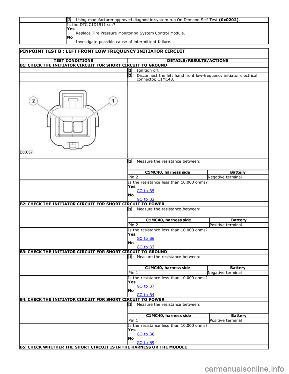
3 Using manufacturer approved diagnostic system run On Demand Self Test (0x0202). Is the DTC C1D1911 set?
Yes
Replace Tire Pressure Monitoring System Control Module.
No
Investigate possible cause of intermittent failure.
PINPOINT TEST B : LEFT FRONT LOW FREQUENCY INITIATOR CIRCUIT TEST CONDITIONS DETAILS/RESULTS/ACTIONS B1: CHECK THE INITIATOR CIRCUIT FOR SHORT CIRCUIT TO GROUND 1 Ignition off. 2 Disconnect the left hand front low-frequency initiator electrical connector, C1MC40. 3 Measure the resistance between: C1MC40, harness side Battery Pin 2 Negative terminal Is the resistance less than 10,000 ohms?
Yes
GO to B5. No
GO to B2. B2: CHECK THE INITIATOR CIRCUIT FOR SHORT CIRCUIT TO POWER 1 Measure the resistance between: C1MC40, harness side Battery Pin 2 Positive terminal Is the resistance less than 10,000 ohms?
Yes
GO to B6. No
GO to B3. B3: CHECK THE INITIATOR CIRCUIT FOR SHORT CIRCUIT TO GROUND 1 Measure the resistance between: C1MC40, harness side Battery Pin 1 Negative terminal Is the resistance less than 10,000 ohms?
Yes
GO to B7. No
GO to B4. B4: CHECK THE INITIATOR CIRCUIT FOR SHORT CIRCUIT TO POWER 1 Measure the resistance between: C1MC40, harness side Battery Pin 1 Positive terminal Is the resistance less than 10,000 ohms?
Yes
GO to B8. No
GO to B9. B5: CHECK WHETHER THE SHORT CIRCUIT IS IN THE HARNESS OR THE MODULE
Page 454 of 3039
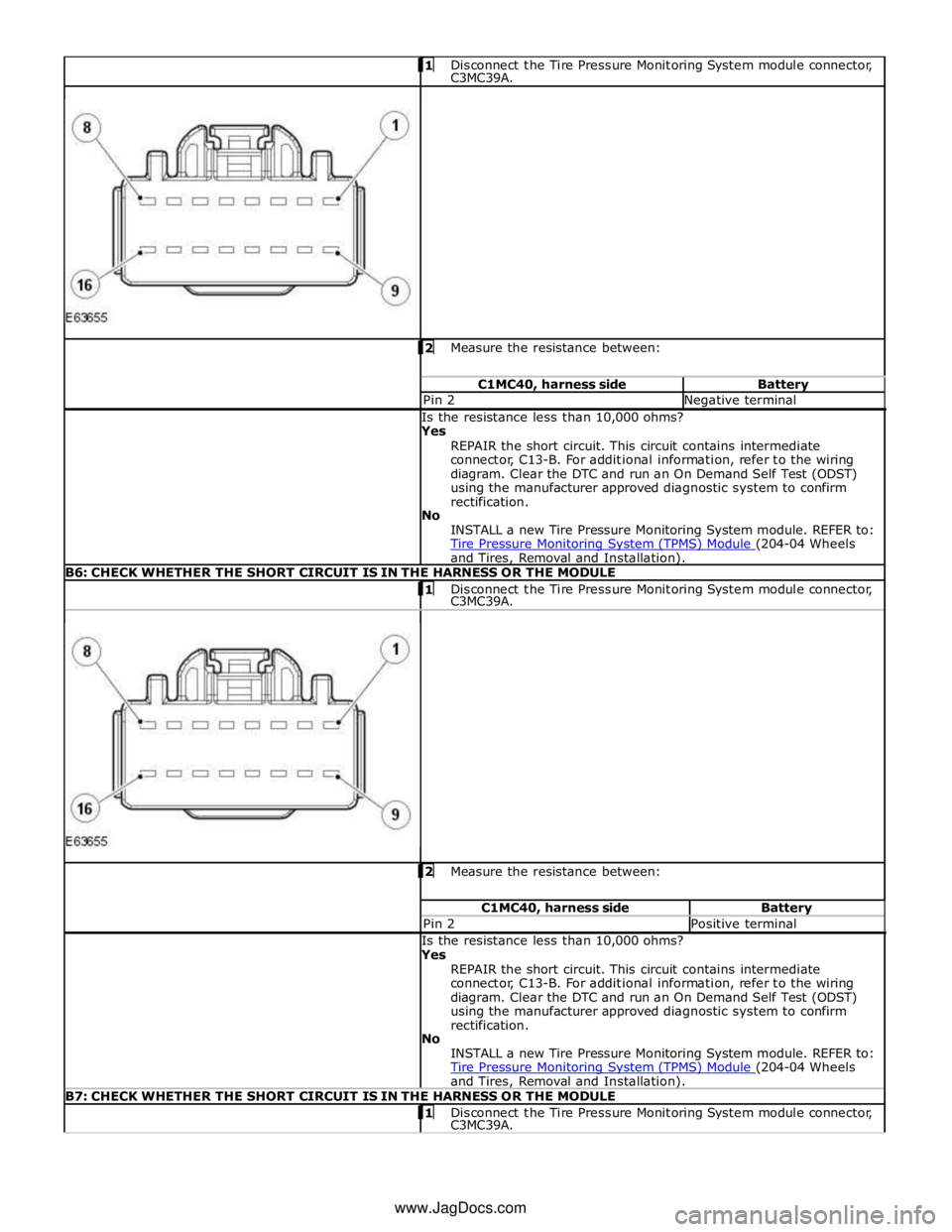
Disconnect the Tire Pressure Monitoring System module connector, C3MC39A.
2 Measure the resistance between: C1MC40, harness side Battery Pin 2 Negative terminal Is the resistance less than 10,000 ohms?
Yes
REPAIR the short circuit. This circuit contains intermediate
connector, C13-B. For additional information, refer to the wiring
diagram. Clear the DTC and run an On Demand Self Test (ODST)
using the manufacturer approved diagnostic system to confirm
rectification.
No
INSTALL a new Tire Pressure Monitoring System module. REFER to:
Tire Pressure Monitoring System (TPMS) Module (204-04 Wheels and Tires, Removal and Installation). B6: CHECK WHETHER THE SHORT CIRCUIT IS IN THE HARNESS OR THE MODULE 1 Disconnect the Tire Pressure Monitoring System module connector, C3MC39A. 2 Measure the resistance between: C1MC40, harness side Battery Pin 2 Positive terminal Is the resistance less than 10,000 ohms?
Yes
REPAIR the short circuit. This circuit contains intermediate
connector, C13-B. For additional information, refer to the wiring
diagram. Clear the DTC and run an On Demand Self Test (ODST)
using the manufacturer approved diagnostic system to confirm
rectification.
No
INSTALL a new Tire Pressure Monitoring System module. REFER to:
Tire Pressure Monitoring System (TPMS) Module (204-04 Wheels and Tires, Removal and Installation). B7: CHECK WHETHER THE SHORT CIRCUIT IS IN THE HARNESS OR THE MODULE 1 Disconnect the Tire Pressure Monitoring System module connector, C3MC39A. www.JagDocs.com
Page 455 of 3039
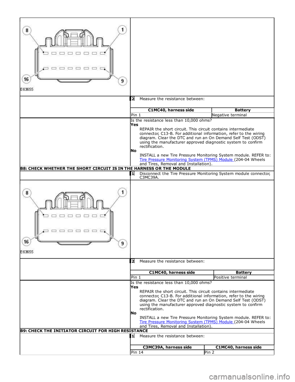
2 Measure the resistance between: C1MC40, harness side Battery Pin 1 Negative terminal Is the resistance less than 10,000 ohms?
Yes
REPAIR the short circuit. This circuit contains intermediate
connector, C13-B. For additional information, refer to the wiring
diagram. Clear the DTC and run an On Demand Self Test (ODST)
using the manufacturer approved diagnostic system to confirm
rectification.
No
INSTALL a new Tire Pressure Monitoring System module. REFER to:
Tire Pressure Monitoring System (TPMS) Module (204-04 Wheels and Tires, Removal and Installation). B8: CHECK WHETHER THE SHORT CIRCUIT IS IN THE HARNESS OR THE MODULE 1 Disconnect the Tire Pressure Monitoring System module connector, C3MC39A. 2 Measure the resistance between: C1MC40, harness side Battery Pin 1 Positive terminal Is the resistance less than 10,000 ohms?
Yes
REPAIR the short circuit. This circuit contains intermediate
connector, C13-B. For additional information, refer to the wiring
diagram. Clear the DTC and run an On Demand Self Test (ODST)
using the manufacturer approved diagnostic system to confirm
rectification.
No
INSTALL a new Tire Pressure Monitoring System module. REFER to:
Tire Pressure Monitoring System (TPMS) Module (204-04 Wheels and Tires, Removal and Installation). B9: CHECK THE INITIATOR CIRCUIT FOR HIGH RESISTANCE 1 Measure the resistance between: C3MC39A, harness side C1MC40, harness side Pin 14 Pin 2
Page 457 of 3039
No
GO to C4. C4: CHECK THE INITIATOR CIRCUIT FOR SHORT CIRCUIT TO POWER 1 Measure the resistance between: C1MC41, harness side Battery Pin 1 Positive terminal Is the resistance less than 10,000 ohms?
Yes
GO to C8. No
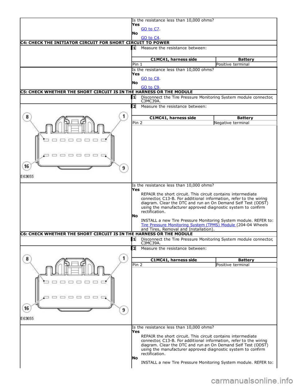
GO to C9. C5: CHECK WHETHER THE SHORT CIRCUIT IS IN THE HARNESS OR THE MODULE 1 Disconnect the Tire Pressure Monitoring System module connector, C3MC39A.
2 Measure the resistance between: C1MC41, harness side Battery Pin 2 Negative terminal Is the resistance less than 10,000 ohms?
Yes
REPAIR the short circuit. This circuit contains intermediate
connector, C13-B. For additional information, refer to the wiring
diagram. Clear the DTC and run an On Demand Self Test (ODST)
using the manufacturer approved diagnostic system to confirm
rectification.
No
INSTALL a new Tire Pressure Monitoring System module. REFER to:
Tire Pressure Monitoring System (TPMS) Module (204-04 Wheels and Tires, Removal and Installation). C6: CHECK WHETHER THE SHORT CIRCUIT IS IN THE HARNESS OR THE MODULE 1 Disconnect the Tire Pressure Monitoring System module connector, C3MC39A.
2 Measure the resistance between: C1MC41, harness side Battery Pin 2 Positive terminal Is the resistance less than 10,000 ohms?
Yes
REPAIR the short circuit. This circuit contains intermediate
connector, C13-B. For additional information, refer to the wiring
diagram. Clear the DTC and run an On Demand Self Test (ODST)
using the manufacturer approved diagnostic system to confirm
rectification.
No
INSTALL a new Tire Pressure Monitoring System module. REFER to:
Page 458 of 3039
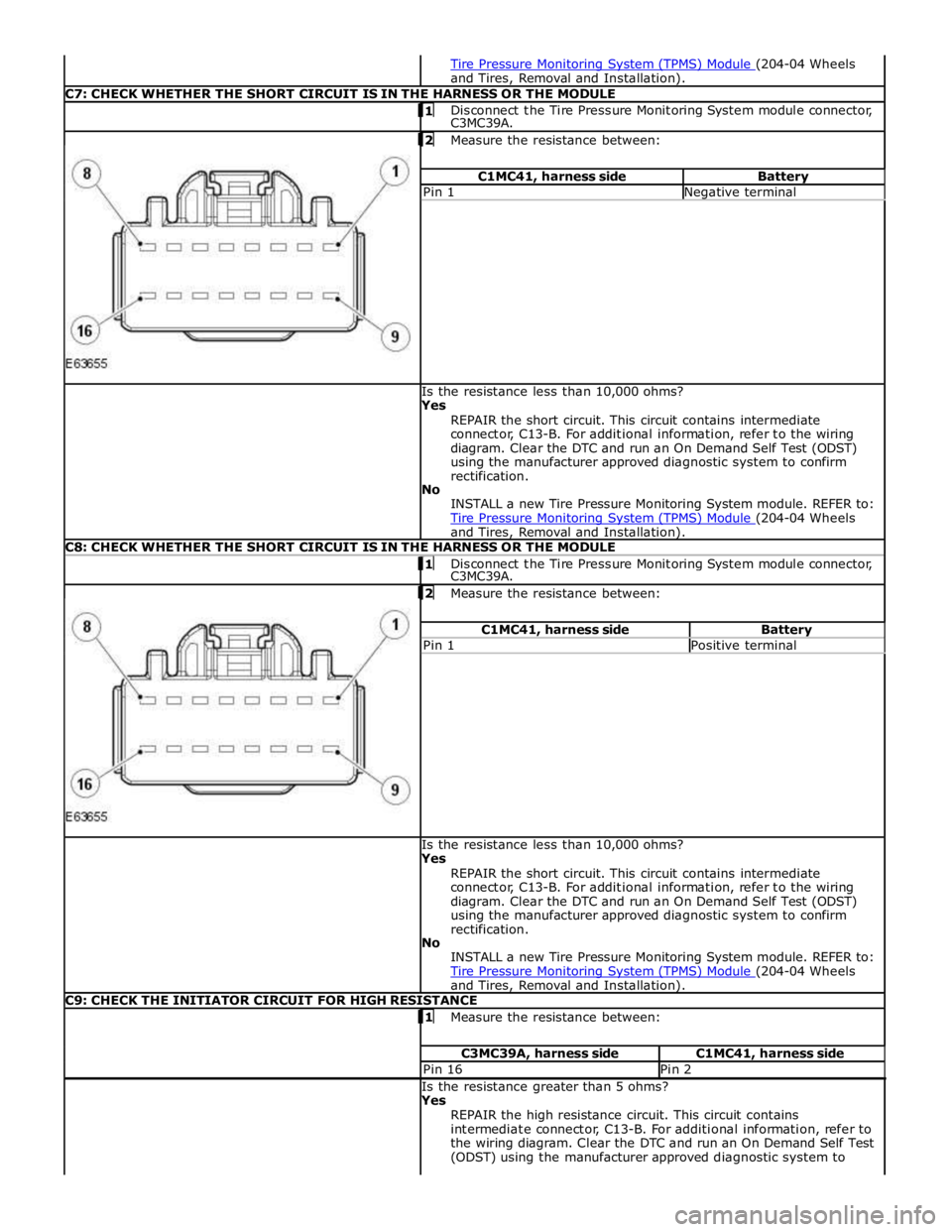
and Tires, Removal and Installation). C7: CHECK WHETHER THE SHORT CIRCUIT IS IN THE HARNESS OR THE MODULE 1 Disconnect the Tire Pressure Monitoring System module connector, C3MC39A.
2 Measure the resistance between: C1MC41, harness side Battery Pin 1 Negative terminal Is the resistance less than 10,000 ohms?
Yes
REPAIR the short circuit. This circuit contains intermediate
connector, C13-B. For additional information, refer to the wiring
diagram. Clear the DTC and run an On Demand Self Test (ODST)
using the manufacturer approved diagnostic system to confirm
rectification.
No
INSTALL a new Tire Pressure Monitoring System module. REFER to:
Tire Pressure Monitoring System (TPMS) Module (204-04 Wheels and Tires, Removal and Installation). C8: CHECK WHETHER THE SHORT CIRCUIT IS IN THE HARNESS OR THE MODULE 1 Disconnect the Tire Pressure Monitoring System module connector, C3MC39A.
2 Measure the resistance between: C1MC41, harness side Battery Pin 1 Positive terminal Is the resistance less than 10,000 ohms?
Yes
REPAIR the short circuit. This circuit contains intermediate
connector, C13-B. For additional information, refer to the wiring
diagram. Clear the DTC and run an On Demand Self Test (ODST)
using the manufacturer approved diagnostic system to confirm
rectification.
No
INSTALL a new Tire Pressure Monitoring System module. REFER to:
Tire Pressure Monitoring System (TPMS) Module (204-04 Wheels and Tires, Removal and Installation). C9: CHECK THE INITIATOR CIRCUIT FOR HIGH RESISTANCE 1 Measure the resistance between: C3MC39A, harness side C1MC41, harness side Pin 16 Pin 2 Is the resistance greater than 5 ohms?
Yes
REPAIR the high resistance circuit. This circuit contains
intermediate connector, C13-B. For additional information, refer to
the wiring diagram. Clear the DTC and run an On Demand Self Test
(ODST) using the manufacturer approved diagnostic system to