battery monitoring module JAGUAR XFR 2010 1.G Repair Manual
[x] Cancel search | Manufacturer: JAGUAR, Model Year: 2010, Model line: XFR, Model: JAGUAR XFR 2010 1.GPages: 3039, PDF Size: 58.49 MB
Page 2097 of 3039

DTC Description Possible Causes Action B111E13 Boot/Trunk Lamps
Luggage compartment
lamp control circuit -
open circuit Refer to the electrical circuit diagrams and check luggage
compartment lamp control circuit for open circuit B111E-15 Boot/Trunk Lamps
- circuit short to
battery or open
Luggage compartment
lamp inoperative
Luggage compartment
lamp control circuit -
short circuit to power,
open circuit, high
resistance
Refer to the electrical circuit diagrams and check luggage
compartment lamp control circuit for short circuit to
power, open circuit, high resistance. Repair wiring harness
as required. Clear DTC and retest B112312
Restraints
Ignition Relay
High Side output not
driven - diagnosis
feedback indicates output
is short to power Carry out any pinpoint test associated with this DTC using the
manufacturer approved diagnostic system. Refer to the electrical
circuit diagrams and check restraints ignition relay output for
short to power B112314
Restraints
Ignition Relay
High Side output not
driven - diagnosis
feedback indicates output
is short to ground, open
circuit Carry out any pinpoint test associated with this DTC using the
manufacturer approved diagnostic system. Refer to the electrical
circuit diagrams and check restraints ignition relay output for
short to ground, open circuit B112393
Restraints
Ignition Relay
High Side output not
driven - diagnosis
feedback indicates output
is at open load or short
to power Carry out any pinpoint test associated with this DTC using the
manufacturer approved diagnostic system. Refer to the electrical
circuit diagrams and check restraints ignition relay output for
open load or short to power B112411
Lamp Fade
Control
Interior lamp fade control
circuit - short to ground Refer to the electrical circuit diagrams and check interior lamp
fade control circuit for short to ground B112412
Lamp Fade
Control
Interior lamp fade control
circuit - short to power Refer to the electrical circuit diagrams and check interior lamp
fade control circuit for short to power B113C12
Hazard Switch
Illumination
Hazard switch
illumination control
circuit - short to power Refer to the electrical circuit diagrams and check hazard switch
illumination control circuit for short to power B113C14
Hazard Switch
Illumination
Hazard switch
illumination control
circuit - short to ground,
open circuit Refer to the electrical circuit diagrams and check hazard switch
illumination control circuit for short to ground, open circuit B113E12
External
Boot/Trunk
Release Switch
External luggage
compartment lid release
switch digital input circuit
- short to power Refer to the electrical circuit diagrams and check external
luggage compartment lid release switch digital input circuit for
short to power B113E23
External
Boot/Trunk
Release Switch
External luggage
compartment lid release
switch digital input circuit
- signal stuck low Carry out any pinpoint test associated with this DTC using the
manufacturer approved diagnostic system. Refer to the electrical
circuit diagrams and check external luggage compartment lid
release switch digital input circuit for short to ground B11D949 Vehicle Battery
Vehicle battery
damaged/worn out Check battery is in fully charged and serviceable condition using
the Midtronics battery tester and the battery care manual B11DB49
Battery
Monitoring
Module
Internal electronic failure Suspect the battery monitoring module. Check and install a new
module as required, refer to the new module/component
installation note at the top of the DTC Index B11DB87
Battery
Monitoring
Module
Battery monitoring
module connector
dis-connected/poor
connection Battery
monitoring
module to RJB LIN circuit
- open circuit Carry out any pinpoint test associated with this DTC using the
manufacturer approved diagnostic system. If additional DTCs
B108783, B108786, B108787 are logged, suspect the RJB. Check
and install a new RJB as required, refer to the new
module/component installation note at the top of the DTC Index.
If additional DTCs B108783, B108786, B108787 are NOT logged,
check for good/clean contact at battery monitoring module
Page 2098 of 3039

DTC Description Possible Causes Action Battery monitoring
module to battery
positive monitor circuit -
open circuit
Battery monitoring
module/RJB failure connector, refer to electrical circuit diagrams and check battery
monitoring module to RJB LIN circuit and battery monitoring
module to battery positive monitor circuit for open circuit. Clear
DTC and repeat automated diagnostic procedure using
manufacturer approved diagnostic system. If DTC remains
suspect the battery monitoring module, check and install a new
battery monitoring module as required, refer to the new
module/component installation note at the top of the DTC Index B123A11
Left Front Turn
Indicator
Left front turn signal
lamp control circuit -
short to ground Refer to the electrical circuit diagrams and check left front turn
signal lamp control circuit for short to ground B123A12
Left Front Turn
Indicator
Left front turn signal
lamp control circuit -
short to power Refer to the electrical circuit diagrams and check left front turn
signal lamp control circuit for short to power B123A13
Left Front Turn
Indicator
Left front turn signal
lamp control circuit -
open circuit Refer to the electrical circuit diagrams and check left front turn
signal lamp control circuit for open circuit B123A-15
Left Front Turn
Indicator - circuit
short to battery
or open
Left front turn signal
lamp control circuit -
short circuit to power,
open circuit, high
resistance
Refer to electrical circuit diagrams and check left front
turn signal lamp control circuit for short circuit to power,
open circuit, high resistance. Repair wiring harness as
required. Clear DTC and retest B123B11
Right Front Turn
Indicator
Right front turn signal
lamp control circuit -
short to ground Refer to the electrical circuit diagrams and check right front turn
signal lamp control circuit for short to ground B123B12
Right Front Turn
Indicator
Right front turn signal
lamp control circuit -
short to power Refer to the electrical circuit diagrams and check right front turn
signal lamp control circuit for short to power B123B13
Right Front Turn
Indicator
Right front turn signal
lamp control circuit -
open circuit Refer to the electrical circuit diagrams and check right front turn
signal lamp control circuit for open circuit B123B-15
Right Front Turn
Indicator - circuit
short to battery
or open
Right front turn signal
lamp control circuit -
short circuit to power,
open circuit, high
resistance
Refer to electrical circuit diagrams and check right front
turn signal lamp control circuit for short circuit to power,
open circuit, high resistance. Repair wiring harness as
required. Clear DTC and retest B124711
Left Rear Turn
Indicator
Left rear turn signal lamp
control circuit - short to
ground Refer to the electrical circuit diagrams and check left rear turn
signal lamp control circuit for short to ground B124712
Left Rear Turn
Indicator
Left rear turn signal lamp
control circuit - short to
power Refer to the electrical circuit diagrams and check left rear turn
signal lamp control circuit for short to power B124713
Left Rear Turn
Indicator
Left rear turn signal lamp
control circuit - short to
power, open circuit Refer to the electrical circuit diagrams and check left rear turn
signal lamp control circuit for open circuit B1247-15
Left Rear Turn
Indicator - circuit
short to battery
or open
Left rear turn signal lamp
control circuit - short
circuit to power, open
circuit, high resistance
Refer to electrical circuit diagrams and check left rear turn
signal lamp control circuit for short circuit to power, open
circuit, high resistance. Repair wiring harness as required.
Clear DTC and retest B124811
Right Rear Turn
Indicator
Right rear turn signal
lamp control circuit -
short to ground Refer to the electrical circuit diagrams and check right rear turn
signal lamp control circuit for short to ground
Page 2123 of 3039
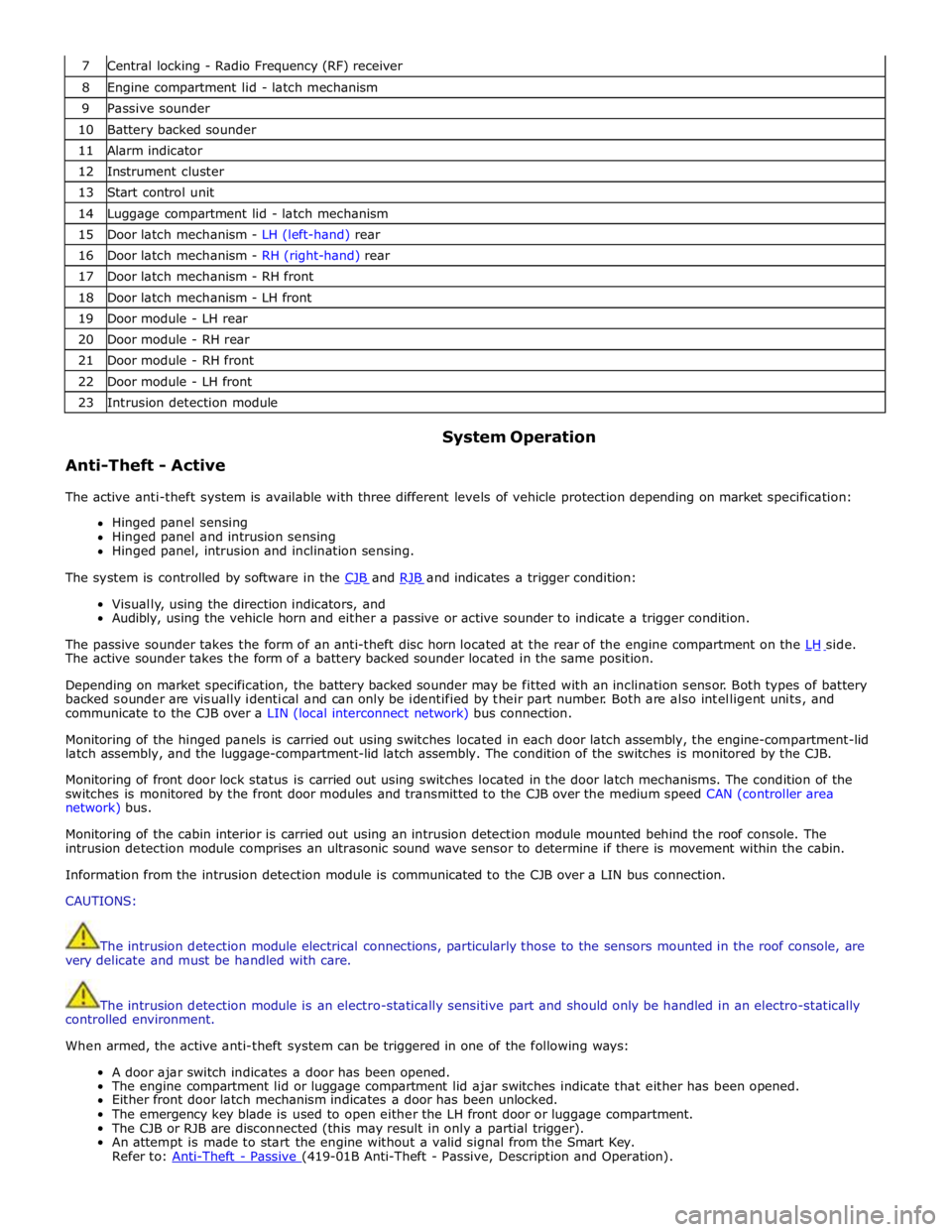
7 Central locking - Radio Frequency (RF) receiver 8 Engine compartment lid - latch mechanism 9 Passive sounder 10 Battery backed sounder 11 Alarm indicator 12 Instrument cluster 13 Start control unit 14 Luggage compartment lid - latch mechanism 15 Door latch mechanism - LH (left-hand) rear 16 Door latch mechanism - RH (right-hand) rear 17 Door latch mechanism - RH front 18 Door latch mechanism - LH front 19 Door module - LH rear 20 Door module - RH rear 21 Door module - RH front 22 Door module - LH front 23 Intrusion detection module
Anti-Theft - Active System Operation
The active anti-theft system is available with three different levels of vehicle protection depending on market specification:
Hinged panel sensing
Hinged panel and intrusion sensing
Hinged panel, intrusion and inclination sensing.
The system is controlled by software in the CJB and RJB and indicates a trigger condition: Visually, using the direction indicators, and
Audibly, using the vehicle horn and either a passive or active sounder to indicate a trigger condition.
The passive sounder takes the form of an anti-theft disc horn located at the rear of the engine compartment on the LH side. The active sounder takes the form of a battery backed sounder located in the same position.
Depending on market specification, the battery backed sounder may be fitted with an inclination sensor. Both types of battery
backed sounder are visually identical and can only be identified by their part number. Both are also intelligent units, and
communicate to the CJB over a LIN (local interconnect network) bus connection.
Monitoring of the hinged panels is carried out using switches located in each door latch assembly, the engine-compartment-lid
latch assembly, and the luggage-compartment-lid latch assembly. The condition of the switches is monitored by the CJB.
Monitoring of front door lock status is carried out using switches located in the door latch mechanisms. The condition of the
switches is monitored by the front door modules and transmitted to the CJB over the medium speed CAN (controller area
network) bus.
Monitoring of the cabin interior is carried out using an intrusion detection module mounted behind the roof console. The
intrusion detection module comprises an ultrasonic sound wave sensor to determine if there is movement within the cabin.
Information from the intrusion detection module is communicated to the CJB over a LIN bus connection.
CAUTIONS:
The intrusion detection module electrical connections, particularly those to the sensors mounted in the roof console, are
very delicate and must be handled with care.
The intrusion detection module is an electro-statically sensitive part and should only be handled in an electro-statically
controlled environment.
When armed, the active anti-theft system can be triggered in one of the following ways:
A door ajar switch indicates a door has been opened.
The engine compartment lid or luggage compartment lid ajar switches indicate that either has been opened.
Either front door latch mechanism indicates a door has been unlocked.
The emergency key blade is used to open either the LH front door or luggage compartment.
The CJB or RJB are disconnected (this may result in only a partial trigger).
An attempt is made to start the engine without a valid signal from the Smart Key.
Refer to: Anti-Theft - Passive (419-01B Anti-Theft - Passive, Description and Operation).
Page 2163 of 3039

9 RJB (rear junction box) 10 Battery monitoring system module 11 Rear view camera 12 Driver's side rear door module 13 Driver's door module 14 Driver's seat switches 15 Driver's seat module 16 Start control module 17 Clockspring 18 Battery backed sounder 19 TCM (transmission control module) 20 Generator 21 CJB (central junction box) 22 ECM (engine control module)
Page 2172 of 3039
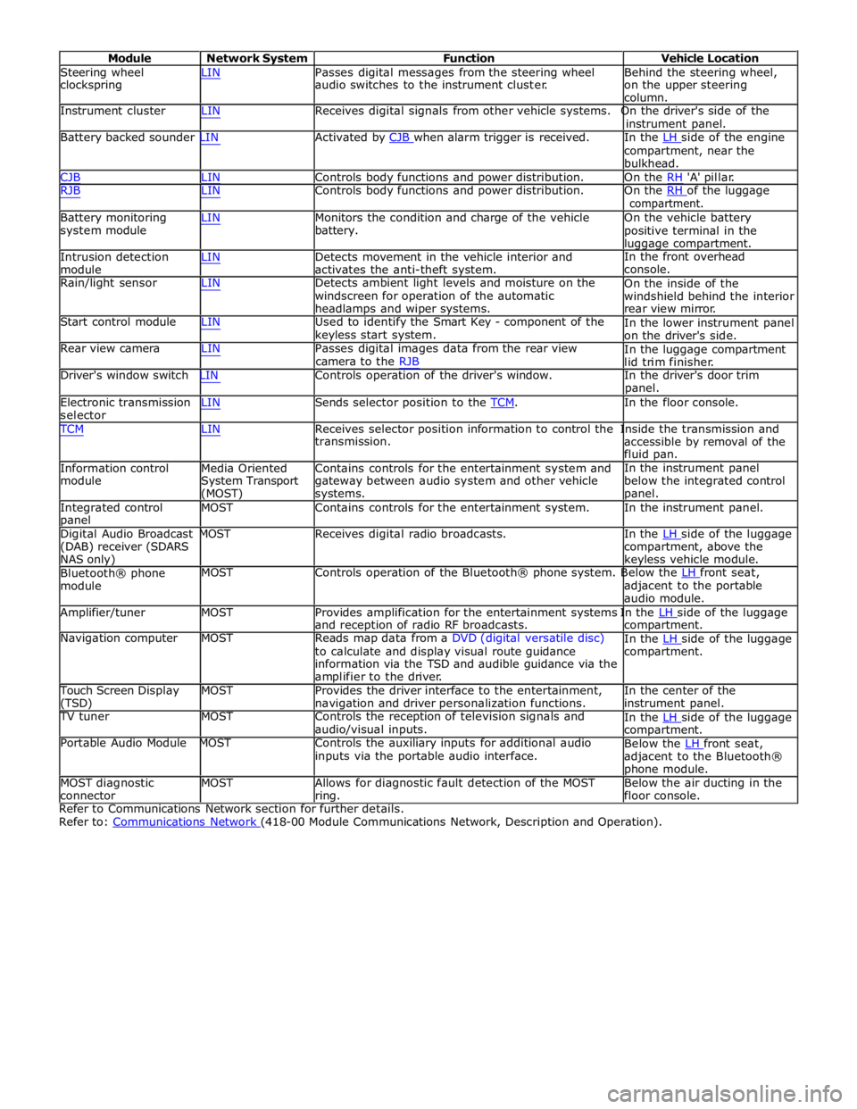
Module Network System Function Vehicle Location
Steering wheel
clockspring LIN Passes digital messages from the steering wheel
audio switches to the instrument cluster. Behind the steering wheel,
on the upper steering
column.
Instrument cluster LIN Receives digital signals from other vehicle systems. On the driver's side of the
instrument panel.
Battery backed sounder LIN Activated by CJB when alarm trigger is received. In the LH side of the engine compartment, near the
bulkhead.
CJB LIN Controls body functions and power distribution. On the RH 'A' pillar.
RJB LIN Controls body functions and power distribution. On the RH of the luggage compartment.
Battery monitoring
system module
Intrusion detection
module LIN Monitors the condition and charge of the vehicle
battery.
LIN Detects movement in the vehicle interior and
activates the anti-theft system. On the vehicle battery
positive terminal in the
luggage compartment.
In the front overhead
console.
Rain/light sensor LIN Detects ambient light levels and moisture on the
windscreen for operation of the automatic
headlamps and wiper systems.
Start control module LIN Used to identify the Smart Key - component of the
keyless start system.
Rear view camera LIN Passes digital images data from the rear view
camera to the RJB On the inside of the
windshield behind the interior
rear view mirror.
In the lower instrument panel
on the driver's side.
In the luggage compartment
lid trim finisher.
Driver's window switch LIN Controls operation of the driver's window. In the driver's door trim
panel.
Electronic transmission
selector LIN Sends selector position to the TCM. In the floor console. TCM LIN Receives selector position information to control the Inside the transmission and
Information control
module
Media Oriented
System Transport
(MOST) transmission.
Contains controls for the entertainment system and
gateway between audio system and other vehicle
systems. accessible by removal of the
fluid pan.
In the instrument panel
below the integrated control
panel.
Integrated control
panel MOST Contains controls for the entertainment system. In the instrument panel.
Digital Audio Broadcast MOST Receives digital radio broadcasts. In the LH side of the luggage (DAB) receiver (SDARS
NAS only)
Bluetooth® phone
module compartment, above the
keyless vehicle module.
MOST Controls operation of the Bluetooth® phone system. Below the LH front seat, adjacent to the portable
audio module.
Amplifier/tuner MOST Provides amplification for the entertainment systems In the LH side of the luggage and reception of radio RF broadcasts.
Navigation computer MOST Reads map data from a DVD (digital versatile disc)
to calculate and display visual route guidance
information via the TSD and audible guidance via the
amplifier to the driver. compartment.
In the LH side of the luggage compartment.
Touch Screen Display
(TSD) MOST Provides the driver interface to the entertainment,
navigation and driver personalization functions. In the center of the
instrument panel.
TV tuner MOST Controls the reception of television signals and
audio/visual inputs.
Portable Audio Module MOST Controls the auxiliary inputs for additional audio
inputs via the portable audio interface. In the LH side of the luggage compartment.
Below the LH front seat, adjacent to the Bluetooth®
phone module.
MOST diagnostic
connector MOST Allows for diagnostic fault detection of the MOST
ring. Below the air ducting in the
floor console.
Refer to Communications Network section for further details.
Refer to: Communications Network (418-00 Module Communications Network, Description and Operation).
Page 2415 of 3039
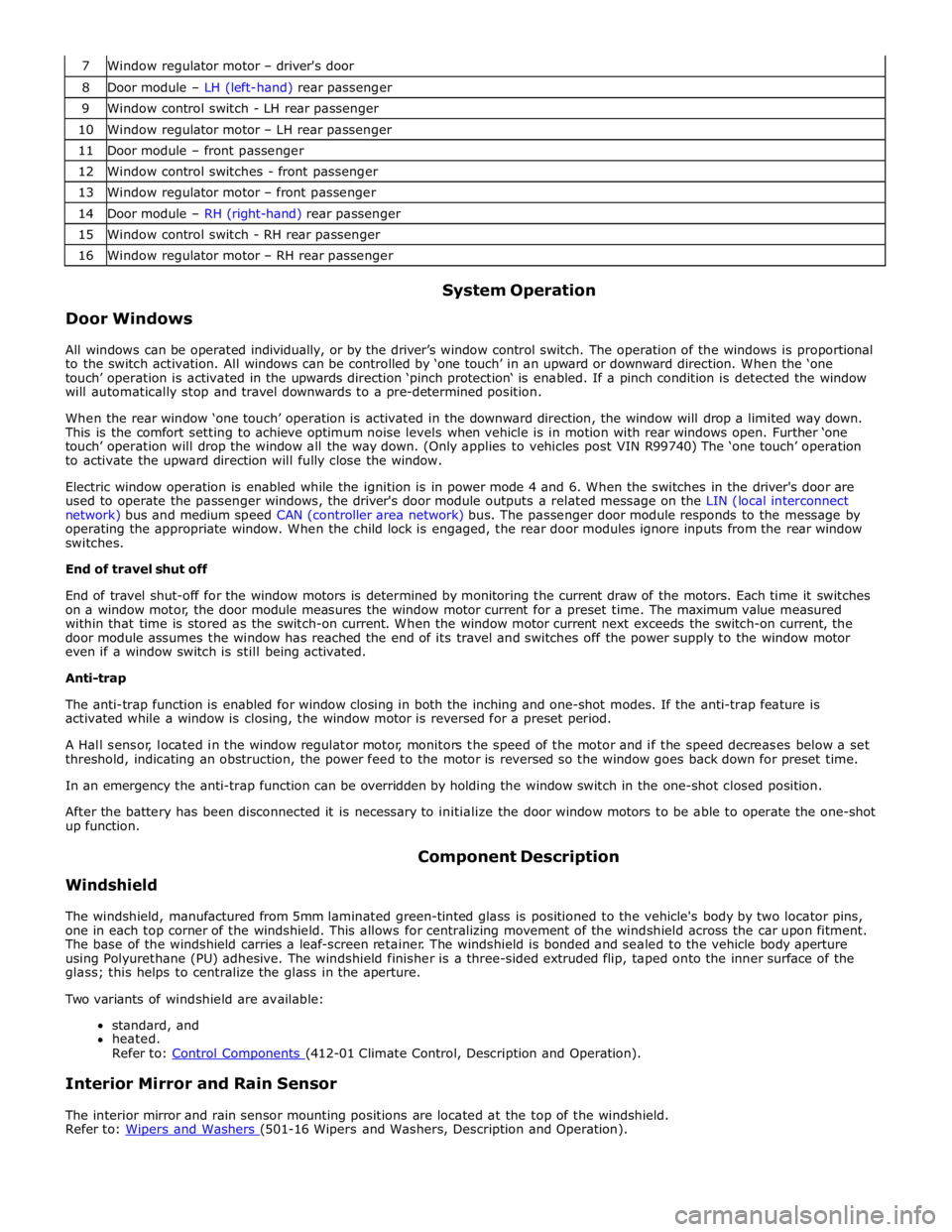
7 Window regulator motor – driver's door 8 Door module – LH (left-hand) rear passenger 9 Window control switch - LH rear passenger 10 Window regulator motor – LH rear passenger 11 Door module – front passenger 12 Window control switches - front passenger 13 Window regulator motor – front passenger 14 Door module – RH (right-hand) rear passenger 15 Window control switch - RH rear passenger 16 Window regulator motor – RH rear passenger
Door Windows System Operation
All windows can be operated individually, or by the driver’s window control switch. The operation of the windows is proportional
to the switch activation. All windows can be controlled by ‘one touch’ in an upward or downward direction. When the ‘one
touch’ operation is activated in the upwards direction ‘pinch protection‘ is enabled. If a pinch condition is detected the window
will automatically stop and travel downwards to a pre-determined position.
When the rear window ‘one touch’ operation is activated in the downward direction, the window will drop a limited way down.
This is the comfort setting to achieve optimum noise levels when vehicle is in motion with rear windows open. Further ‘one
touch’ operation will drop the window all the way down. (Only applies to vehicles post VIN R99740) The ‘one touch’ operation
to activate the upward direction will fully close the window.
Electric window operation is enabled while the ignition is in power mode 4 and 6. When the switches in the driver's door are
used to operate the passenger windows, the driver's door module outputs a related message on the LIN (local interconnect
network) bus and medium speed CAN (controller area network) bus. The passenger door module responds to the message by
operating the appropriate window. When the child lock is engaged, the rear door modules ignore inputs from the rear window
switches.
End of travel shut off
End of travel shut-off for the window motors is determined by monitoring the current draw of the motors. Each time it switches
on a window motor, the door module measures the window motor current for a preset time. The maximum value measured
within that time is stored as the switch-on current. When the window motor current next exceeds the switch-on current, the
door module assumes the window has reached the end of its travel and switches off the power supply to the window motor
even if a window switch is still being activated.
Anti-trap
The anti-trap function is enabled for window closing in both the inching and one-shot modes. If the anti-trap feature is
activated while a window is closing, the window motor is reversed for a preset period.
A Hall sensor, located in the window regulator motor, monitors the speed of the motor and if the speed decreases below a set
threshold, indicating an obstruction, the power feed to the motor is reversed so the window goes back down for preset time.
In an emergency the anti-trap function can be overridden by holding the window switch in the one-shot closed position.
After the battery has been disconnected it is necessary to initialize the door window motors to be able to operate the one-shot
up function.
Windshield Component Description
The windshield, manufactured from 5mm laminated green-tinted glass is positioned to the vehicle's body by two locator pins,
one in each top corner of the windshield. This allows for centralizing movement of the windshield across the car upon fitment.
The base of the windshield carries a leaf-screen retainer. The windshield is bonded and sealed to the vehicle body aperture
using Polyurethane (PU) adhesive. The windshield finisher is a three-sided extruded flip, taped onto the inner surface of the
glass; this helps to centralize the glass in the aperture.
Two variants of windshield are available:
standard, and
heated.
Refer to: Control Components (412-01 Climate Control, Description and Operation).
Interior Mirror and Rain Sensor
The interior mirror and rain sensor mounting positions are located at the top of the windshield.
Refer to: Wipers and Washers (501-16 Wipers and Washers, Description and Operation).
Page 2615 of 3039
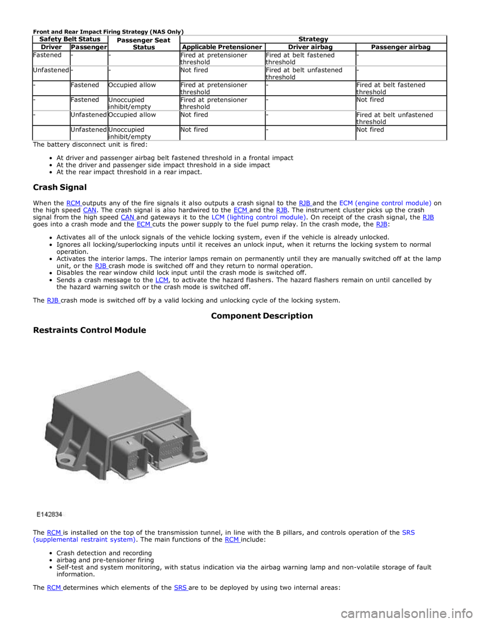
Driver Passenger Applicable Pretensioner Driver airbag Passenger airbag Fastened - -
Fired at pretensioner
threshold Fired at belt fastened
threshold - Unfastened - - Not fired
Fired at belt unfastened
threshold - - Fastened Occupied allow
Fired at pretensioner
threshold -
Fired at belt fastened
threshold - Fastened
Unoccupied inhibit/empty Fired at pretensioner
threshold - Not fired - Unfastened Occupied allow Not fired -
Fired at belt unfastened
threshold Unfastened
Unoccupied inhibit/empty Not fired - Not fired The battery disconnect unit is fired:
At driver and passenger airbag belt fastened threshold in a frontal impact
At the driver and passenger side impact threshold in a side impact
At the rear impact threshold in a rear impact.
Crash Signal
When the RCM outputs any of the fire signals it also outputs a crash signal to the RJB and the ECM (engine control module) on the high speed CAN. The crash signal is also hardwired to the ECM and the RJB. The instrument cluster picks up the crash signal from the high speed CAN and gateways it to the LCM (lighting control module). On receipt of the crash signal, the RJB goes into a crash mode and the ECM cuts the power supply to the fuel pump relay. In the crash mode, the RJB: Activates all of the unlock signals of the vehicle locking system, even if the vehicle is already unlocked.
Ignores all locking/superlocking inputs until it receives an unlock input, when it returns the locking system to normal
operation.
Activates the interior lamps. The interior lamps remain on permanently until they are manually switched off at the lamp
unit, or the RJB crash mode is switched off and they return to normal operation. Disables the rear window child lock input until the crash mode is switched off.
Sends a crash message to the LCM, to activate the hazard flashers. The hazard flashers remain on until cancelled by the hazard warning switch or the crash mode is switched off.
The RJB crash mode is switched off by a valid locking and unlocking cycle of the locking system.
Restraints Control Module Component Description
The RCM is installed on the top of the transmission tunnel, in line with the B pillars, and controls operation of the SRS (supplemental restraint system). The main functions of the RCM include:
Crash detection and recording
airbag and pre-tensioner firing
Self-test and system monitoring, with status indication via the airbag warning lamp and non-volatile storage of fault
information.
The RCM determines which elements of the SRS are to be deployed by using two internal areas:
Page 2616 of 3039
and the safety belt buckle sensor. Based on this data, the RCM decides which level of airbag module deployment is required and forwards the information to the second area, the deployment handler.
The deployment handler evaluates the status of the seat track position sensor and safety belt buckle sensors before a decision
is made about which restraints should finally be deployed.
Data from the side crash sensors is used by the RCM in conjunction with acceleration data from the RCM internal accelerometer to make a deployment decision. The RCM processes the acceleration data and subject to an impact being of high enough severity, decides whether the side airbag module should be deployed.
On board testing of the airbag modules, front safety belt pretensioner firing circuits, warning indicator circuits and module
status (the crash and side impact sensors perform basic self-tests) is performed by the RCM together with the storing of fault codes.
The RCM drives the SRS indicator on the instrument pack via a CAN signal. If the warning lamp fails, a fault code is recorded and a warning tone is sounded in place of the lamp if a further fault occurs. It also provides a temporary back-up power supply
to operate the airbag modules in the event that in crash conditions, the battery supply is lost. In the event of a crash, it
records certain data which can be accessed via the diagnostic connector.
A safing sensor in the RCM provides confirmation of an impact to verify if airbag and pretensioner activation is necessary. A roll-over sensor monitors the lateral attitude of the vehicle. Various firing strategies are employed by the RCM to ensure that during an accident only the appropriate airbags and pretensioners are fired. The firing strategy used also depends on the
inputs from the safety belt switches and the occupant monitoring system.
An energy reserve in the RCM ensures there is always a minimum of 150 milliseconds of stored energy available if the power supply from the ignition switch is disrupted during a crash. The stored energy is sufficient to produce firing signals for the
driver airbag, the passenger airbag and the safety belt pretensioners.
When the ignition is switched on, the RCM performs a self-test and then performs cyclical monitoring of the system. If a fault is detected the RCM stores a related fault code and illuminates the airbag warning indicator. The faults can be retrieved by the recommended Jaguar diagnostic tool over the CAN bus. If a fault that could cause a false fire signal is detected, the RCM disables the respective firing circuit, and keeps it disabled during a crash event.
Clock Spring
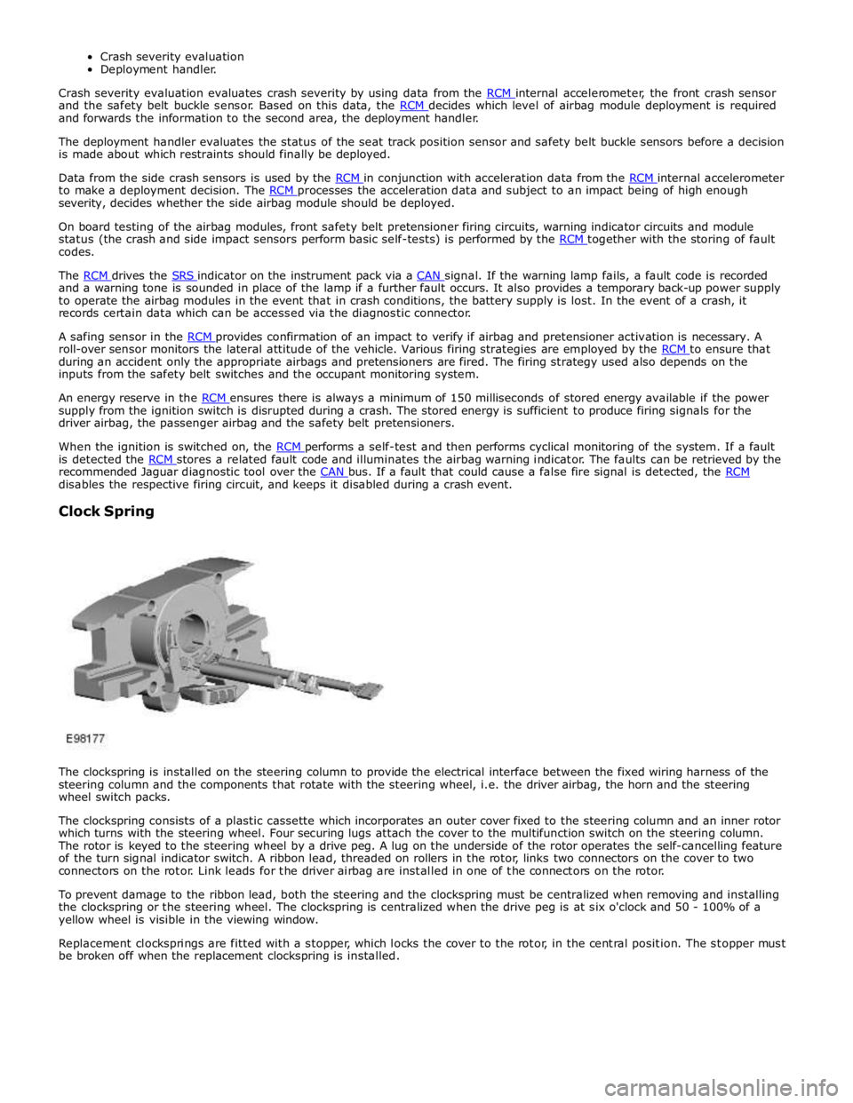
The clockspring is installed on the steering column to provide the electrical interface between the fixed wiring harness of the
steering column and the components that rotate with the steering wheel, i.e. the driver airbag, the horn and the steering
wheel switch packs.
The clockspring consists of a plastic cassette which incorporates an outer cover fixed to the steering column and an inner rotor
which turns with the steering wheel. Four securing lugs attach the cover to the multifunction switch on the steering column.
The rotor is keyed to the steering wheel by a drive peg. A lug on the underside of the rotor operates the self-cancelling feature
of the turn signal indicator switch. A ribbon lead, threaded on rollers in the rotor, links two connectors on the cover to two
connectors on the rotor. Link leads for the driver airbag are installed in one of the connectors on the rotor.
To prevent damage to the ribbon lead, both the steering and the clockspring must be centralized when removing and installing
the clockspring or the steering wheel. The clockspring is centralized when the drive peg is at six o'clock and 50 - 100% of a
yellow wheel is visible in the viewing window.
Replacement clocksprings are fitted with a stopper, which locks the cover to the rotor, in the central position. The stopper must
be broken off when the replacement clockspring is installed.