instrument panel JAGUAR XFR 2010 1.G Owner's Manual
[x] Cancel search | Manufacturer: JAGUAR, Model Year: 2010, Model line: XFR, Model: JAGUAR XFR 2010 1.GPages: 3039, PDF Size: 58.49 MB
Page 267 of 3039
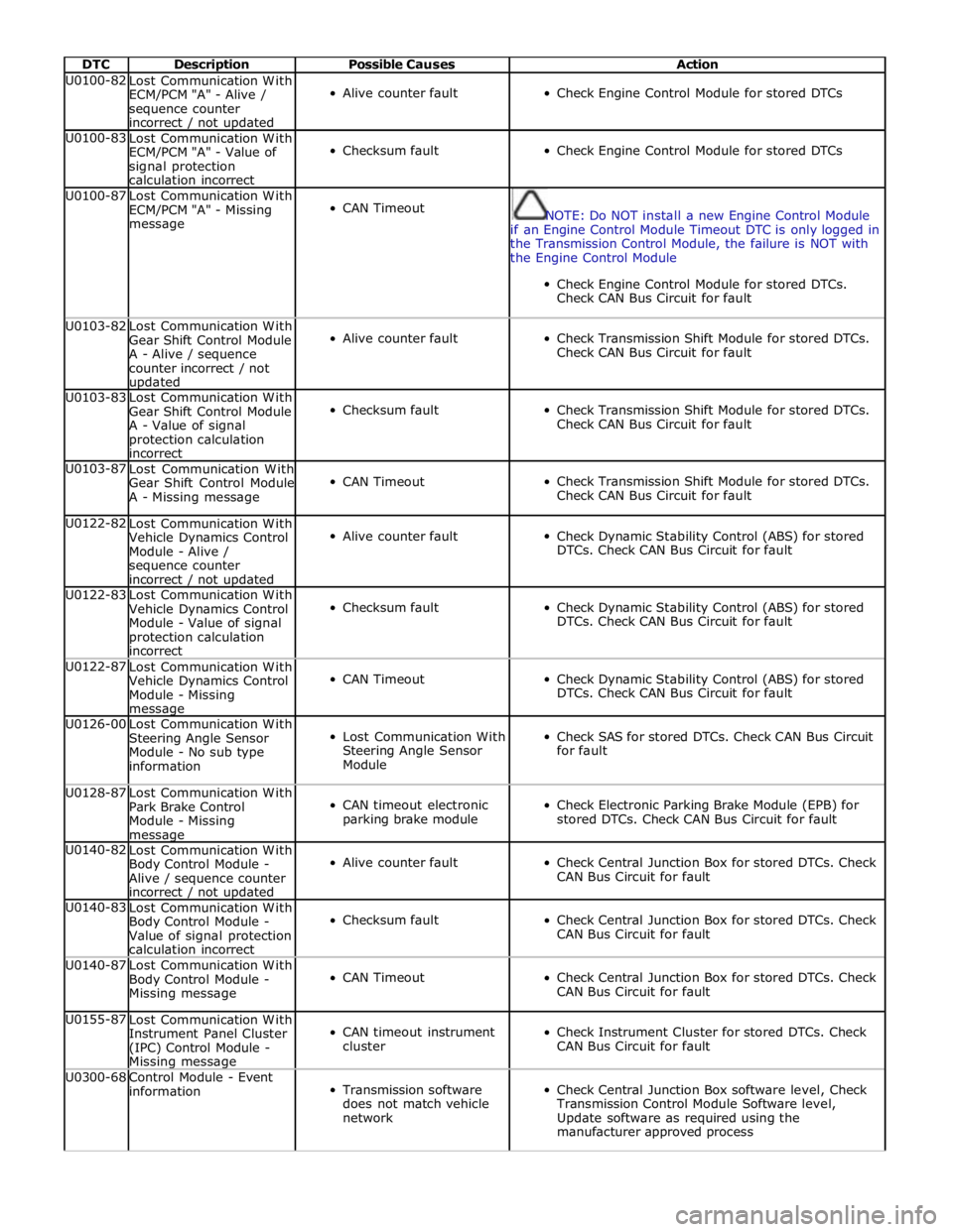
DTC Description Possible Causes Action U0100-82
Lost Communication With
ECM/PCM "A" - Alive /
sequence counter
incorrect / not updated
Alive counter fault
Check Engine Control Module for stored DTCs U0100-83
Lost Communication With
ECM/PCM "A" - Value of
signal protection
calculation incorrect
Checksum fault
Check Engine Control Module for stored DTCs U0100-87
Lost Communication With
ECM/PCM "A" - Missing
message
CAN Timeout
NOTE: Do NOT install a new Engine Control Module
if an Engine Control Module Timeout DTC is only logged in
the Transmission Control Module, the failure is NOT with
the Engine Control Module
Check Engine Control Module for stored DTCs.
Check CAN Bus Circuit for fault U0103-82
Lost Communication With
Gear Shift Control Module
A - Alive / sequence
counter incorrect / not updated
Alive counter fault
Check Transmission Shift Module for stored DTCs.
Check CAN Bus Circuit for fault U0103-83
Lost Communication With
Gear Shift Control Module
A - Value of signal
protection calculation
incorrect
Checksum fault
Check Transmission Shift Module for stored DTCs.
Check CAN Bus Circuit for fault U0103-87
Lost Communication With
Gear Shift Control Module
A - Missing message
CAN Timeout
Check Transmission Shift Module for stored DTCs.
Check CAN Bus Circuit for fault U0122-82
Lost Communication With
Vehicle Dynamics Control
Module - Alive /
sequence counter
incorrect / not updated
Alive counter fault
Check Dynamic Stability Control (ABS) for stored
DTCs. Check CAN Bus Circuit for fault U0122-83
Lost Communication With
Vehicle Dynamics Control
Module - Value of signal
protection calculation
incorrect
Checksum fault
Check Dynamic Stability Control (ABS) for stored
DTCs. Check CAN Bus Circuit for fault U0122-87
Lost Communication With
Vehicle Dynamics Control
Module - Missing message
CAN Timeout
Check Dynamic Stability Control (ABS) for stored
DTCs. Check CAN Bus Circuit for fault U0126-00
Lost Communication With
Steering Angle Sensor
Module - No sub type
information
Lost Communication With
Steering Angle Sensor
Module
Check SAS for stored DTCs. Check CAN Bus Circuit
for fault U0128-87
Lost Communication With
Park Brake Control
Module - Missing message
CAN timeout electronic
parking brake module
Check Electronic Parking Brake Module (EPB) for
stored DTCs. Check CAN Bus Circuit for fault U0140-82
Lost Communication With
Body Control Module -
Alive / sequence counter
incorrect / not updated
Alive counter fault
Check Central Junction Box for stored DTCs. Check
CAN Bus Circuit for fault U0140-83
Lost Communication With
Body Control Module -
Value of signal protection
calculation incorrect
Checksum fault
Check Central Junction Box for stored DTCs. Check
CAN Bus Circuit for fault U0140-87
Lost Communication With
Body Control Module -
Missing message
CAN Timeout
Check Central Junction Box for stored DTCs. Check
CAN Bus Circuit for fault U0155-87
Lost Communication With
Instrument Panel Cluster
(IPC) Control Module - Missing message
CAN timeout instrument
cluster
Check Instrument Cluster for stored DTCs. Check
CAN Bus Circuit for fault U0300-68
Control Module - Event
information
Transmission software
does not match vehicle
network
Check Central Junction Box software level, Check
Transmission Control Module Software level,
Update software as required using the
manufacturer approved process
Page 451 of 3039
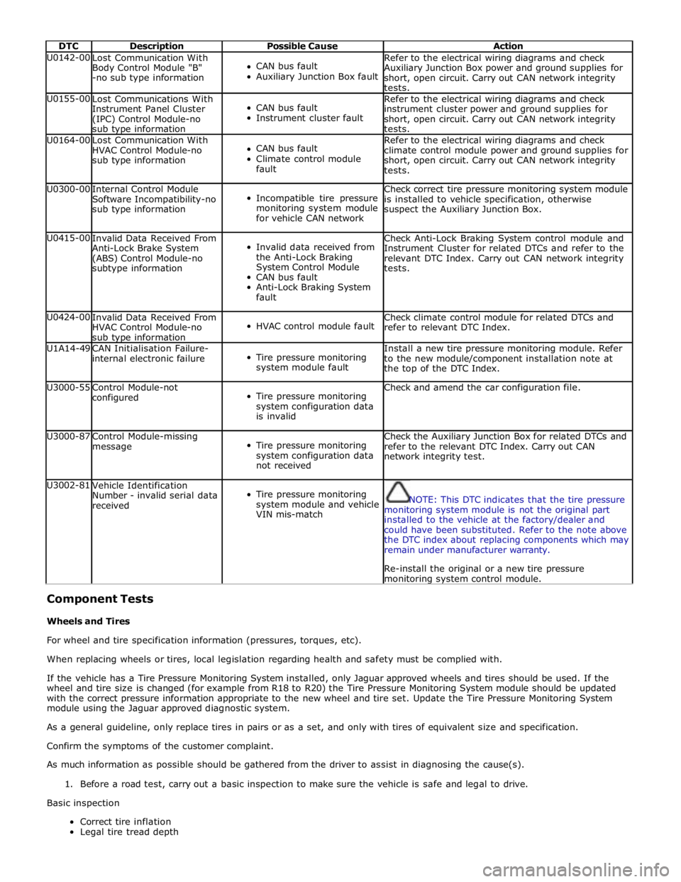
DTC Description Possible Cause Action U0142-00
Lost Communication With
Body Control Module "B"
-no sub type information
CAN bus fault
Auxiliary Junction Box fault Refer to the electrical wiring diagrams and check
Auxiliary Junction Box power and ground supplies for
short, open circuit. Carry out CAN network integrity
tests. U0155-00
Lost Communications With
Instrument Panel Cluster
(IPC) Control Module-no
sub type information
CAN bus fault
Instrument cluster fault Refer to the electrical wiring diagrams and check
instrument cluster power and ground supplies for
short, open circuit. Carry out CAN network integrity
tests. U0164-00
Lost Communication With
HVAC Control Module-no
sub type information
CAN bus fault
Climate control module
fault Refer to the electrical wiring diagrams and check
climate control module power and ground supplies for
short, open circuit. Carry out CAN network integrity
tests. U0300-00
Internal Control Module
Software Incompatibility-no
sub type information
Incompatible tire pressure
monitoring system module
for vehicle CAN network Check correct tire pressure monitoring system module
is installed to vehicle specification, otherwise
suspect the Auxiliary Junction Box. U0415-00
Invalid Data Received From
Anti-Lock Brake System
(ABS) Control Module-no
subtype information
Invalid data received from
the Anti-Lock Braking
System Control Module
CAN bus fault
Anti-Lock Braking System
fault Check Anti-Lock Braking System control module and
Instrument Cluster for related DTCs and refer to the
relevant DTC Index. Carry out CAN network integrity
tests. U0424-00
Invalid Data Received From
HVAC Control Module-no
sub type information
HVAC control module fault Check climate control module for related DTCs and
refer to relevant DTC Index. U1A14-49
CAN Initialisation Failure-
internal electronic failure
Tire pressure monitoring
system module fault Install a new tire pressure monitoring module. Refer
to the new module/component installation note at
the top of the DTC Index. U3000-55
Control Module-not
configured
Tire pressure monitoring
system configuration data
is invalid Check and amend the car configuration file. U3000-87
Control Module-missing
message
Tire pressure monitoring
system configuration data
not received Check the Auxiliary Junction Box for related DTCs and
refer to the relevant DTC Index. Carry out CAN
network integrity test. U3002-81
Vehicle Identification
Number - invalid serial data
received
Tire pressure monitoring
system module and vehicle
VIN mis-match
NOTE: This DTC indicates that the tire pressure
monitoring system module is not the original part
installed to the vehicle at the factory/dealer and
could have been substituted. Refer to the note above
the DTC index about replacing components which may
remain under manufacturer warranty.
Re-install the original or a new tire pressure monitoring system control module.
Component Tests
Wheels and Tires
For wheel and tire specification information (pressures, torques, etc).
When replacing wheels or tires, local legislation regarding health and safety must be complied with.
If the vehicle has a Tire Pressure Monitoring System installed, only Jaguar approved wheels and tires should be used. If the
wheel and tire size is changed (for example from R18 to R20) the Tire Pressure Monitoring System module should be updated
with the correct pressure information appropriate to the new wheel and tire set. Update the Tire Pressure Monitoring System
module using the Jaguar approved diagnostic system.
As a general guideline, only replace tires in pairs or as a set, and only with tires of equivalent size and specification.
Confirm the symptoms of the customer complaint.
As much information as possible should be gathered from the driver to assist in diagnosing the cause(s).
1. Before a road test, carry out a basic inspection to make sure the vehicle is safe and legal to drive.
Basic inspection
Correct tire inflation
Legal tire tread depth
Page 476 of 3039
Published: 11-May-2011
Wheels and Tires - Tire Pressure Monitoring System (TPMS) Receiver
Removal and Installation
Removal
NOTES:
Removal steps in this procedure may contain installation details.
The tire pressure monitoring system receiver is installed in the same location on both LHD and RHD vehicles.
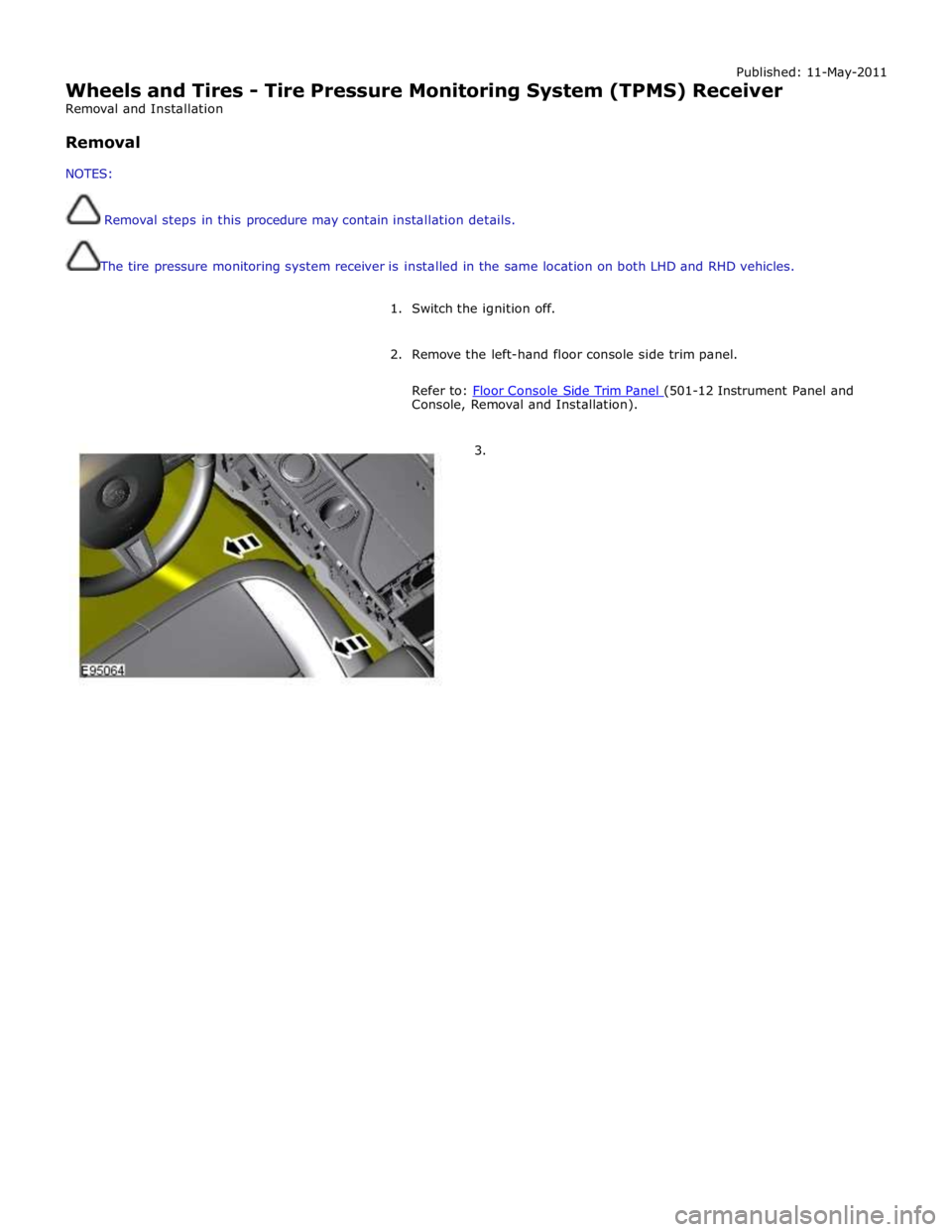
1. Switch the ignition off.
2. Remove the left-hand floor console side trim panel.
Refer to: Floor Console Side Trim Panel (501-12 Instrument Panel and Console, Removal and Installation).
3.
Page 694 of 3039
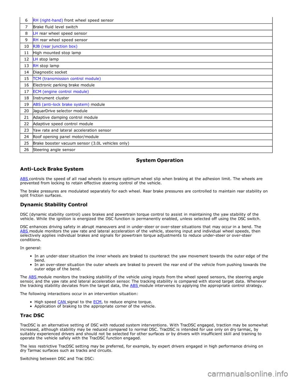
7 Brake fluid level switch 8 LH rear wheel speed sensor 9 RH rear wheel speed sensor 10 RJB (rear junction box) 11 High mounted stop lamp 12 LH stop lamp 13 RH stop lamp 14 Diagnostic socket 15 TCM (transmission control module) 16 Electronic parking brake module 17 ECM (engine control module) 18 Instrument cluster 19 ABS (anti-lock brake system) module 20 JaguarDrive selector module 21 Adaptive damping control module 22 Adaptive speed control module 23 Yaw rate and lateral acceleration sensor 24 Roof opening panel motor/module 25 Brake booster vacuum sensor (3.0L vehicles only) 26 Steering angle sensor
Anti-Lock Brake System System Operation
ABS controls the speed of all road wheels to ensure optimum wheel slip when braking at the adhesion limit. The wheels are prevented from locking to retain effective steering control of the vehicle.
The brake pressures are modulated separately for each wheel. Rear brake pressures are controlled to maintain rear stability on
split friction surfaces.
Dynamic Stability Control
DSC (dynamic stability control) uses brakes and powertrain torque control to assist in maintaining the yaw stability of the
vehicle. While the ignition is energized the DSC function is permanently enabled, unless selected off using the DSC switch.
DSC enhances driving safety in abrupt maneuvers and in under-steer or over-steer situations that may occur in a bend. The
ABS module monitors the yaw rate and lateral acceleration of the vehicle, steering input and individual wheel speeds, then selectively applies individual brakes and signals for powertrain torque adjustments to reduce under-steer or over-steer
conditions.
In general:
In an under-steer situation the inner wheels are braked to counteract the yaw movement towards the outer edge of the
bend.
In an over-steer situation the outer wheels are braked to prevent the rear end of the vehicle from pushing towards the
outer edge of the bend.
The ABS module monitors the tracking stability of the vehicle using inputs from the wheel speed sensors, the steering angle sensor, and the yaw rate and lateral acceleration sensor. The tracking stability is compared with stored target data. Whenever
the tracking stability deviates from the target data, the ABS module intervenes by applying the appropriate control strategy. The following interactions occur in an intervention situation:
High speed CAN signal to the ECM, to reduce engine torque. Application of braking to the appropriate corner of the vehicle.
Trac DSC
TracDSC is an alternative setting of DSC with reduced system interventions. With TracDSC engaged, traction may be somewhat
increased, although stability may be reduced compared to normal DSC. TracDSC is intended for use only on dry tarmac, by
suitably experienced drivers and should not be selected for other surfaces or by drivers with insufficient skill and training to
operate the vehicle safely with the TracDSC function engaged.
The less restrictive TracDSC setting may be preferred, for example, by expert drivers engaged in high performance driving on
dry Tarmac surfaces such as tracks and circuits.
Switching between DSC and Trac DSC:
Page 695 of 3039
Press and hold the DSC switch for less than 10 seconds.
The message center will temporarily display either Trac DSC or DSC ON.
The warning indicator in the instrument panel will illuminate while Trac DSC is selected.
The warning indicator will flash when DSC or Trac DSC is active.
NOTE: If cruise control is engaged, it will automatically disengage if DSC activates.
Refer to: Speed Control (310-03 Speed Control - 2.7L V6 - TdV6, Description and Operation).
Corner Brake Control
CBC (corner brake control) influences the brake pressures, below and within DSC and ABS thresholds, to counteract the yawing moment produced when braking in a corner. CBC produces a correction torque by limiting the brake pressure on one side of the
vehicle.
Electronic Brake Force Distribution
EBD (electronic brake force distribution) limits the brake pressure applied to the rear wheels. When the brakes are applied, the
weight of the vehicle transfers forwards, reducing the ability of the rear wheels to transfer braking effort to the road surface.
This may cause the rear wheels to slip and make the vehicle unstable.
EBD uses the ABS braking hardware to automatically optimize the pressure to the rear brakes, below the point where ABS is normally invoked.
NOTE: Only the rear brakes are controlled by the EBD function.
Electronic Traction Control
ETC (electronic traction control) attempts to optimize forward traction by reducing engine torque, or by applying the brake of a
spinning wheel until traction is regained.
ETC is activated if an individual wheel speed is above that of the vehicle reference speed (positive slip) and the brake pedal is
not pressed. The brake is applied to the spinning wheel, allowing the excess torque to be transmitted to the non-spinning
wheel through the drive line. If necessary, the ABS module also sends a high speed CAN bus message to the ECM to request a reduction in engine torque.
When the DSC function is selected off using the DSC switch, the braking and engine torque reduction features are both
disabled, except when the JaguarDrive control is in winter mode. When the JaguarDrive control is in winter mode, selecting the
DSC function off retains the braking and engine torque reduction features, but reduces intervention levels compared to DSC
and Trac DSC modes.
Emergency Brake Assist
EBA (emergency brake assist) assists the driver in emergency braking situations by automatically increasing the applied
braking effort. The ABS module invokes EBA when: The brake pedal is rapidly pressed.
The brake pedal is pressed hard enough to bring the front brakes into ABS operation.
When the brake pedal is rapidly pressed, the ABS module increases the hydraulic pressure to all of the brakes until the threshold for ABS operation is reached. This action applies the maximum braking effort for the available traction. The ABS module monitors for the sudden application of the brakes, using inputs from the brake pedal switch and from the pressure
sensor within the HCU (hydraulic control unit). With the brake pedal pressed, if the rate of increase of hydraulic pressure
exceeds the predetermined limit, the ABS module invokes emergency braking.
When the brake pedal is pressed hard enough to bring the front brakes into ABS operation, the ABS module increases the hydraulic pressure to the rear brakes up to the ABS threshold.
EBA operation continues until the driver releases the brake pedal, sufficiently for the hydraulic pressure in the HCU to drop below a threshold value stored in the ABS module.
Engine Drag-Torque Control
EDC (engine drag-torque control) prevents wheel slip caused by any of the following: A
sudden decrease in engine torque when the accelerator is suddenly released.
A downshift using the Jaguar sequential shift function on automatic transmission vehicles.
When the ABS module detects the onset of wheel slip without the brakes being applied, the ABS module signals the ECM via the high speed CAN bus to request a momentary increase in engine torque.
Understeer Control
Understeer Logic Control is a proactive system which monitors the vehicle for understeer by comparing signals from the yaw
rate and lateral acceleration sensor with signals from the steering angle sensor and wheel speed sensors. www.JagDocs.com
Page 786 of 3039

Steering Column - Steering Column
Removal and Installation
Removal
NOTE: Removal steps in this procedure may contain installation details. Published: 26-Jun-2014
1. Refer to: Battery Disconnect and Connect (414-01 Battery, Mounting and Cables, General Procedures).
2. Refer to: Instrument Panel Lower Trim Panel (501-12 Instrument Panel and Console, Removal and Installation).
3. Refer to: Steering Wheel Rotation Sensor (206-09 Anti-Lock Control - Stability Assist, Removal and Installation).
4.
5.
Page 790 of 3039
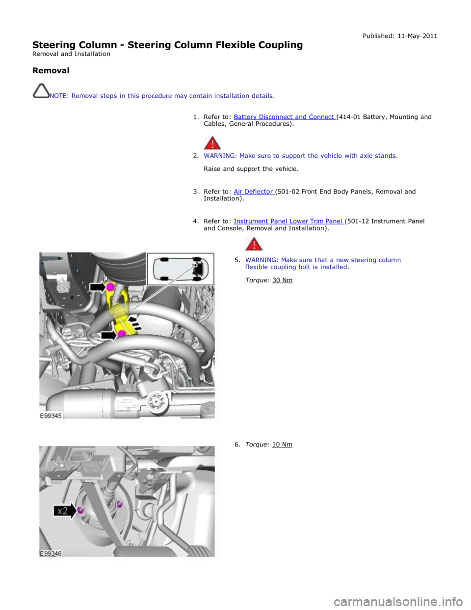
Steering Column - Steering Column Flexible Coupling
Removal and Installation
Removal
NOTE: Removal steps in this procedure may contain installation details. Published: 11-May-2011
1. Refer to: Battery Disconnect and Connect (414-01 Battery, Mounting and Cables, General Procedures).
2. WARNING: Make sure to support the vehicle with axle stands.
Raise and support the vehicle.
3. Refer to: Air Deflector (501-02 Front End Body Panels, Removal and Installation).
4. Refer to: Instrument Panel Lower Trim Panel (501-12 Instrument Panel and Console, Removal and Installation).
5. WARNING: Make sure that a new steering column
flexible coupling bolt is installed.
Torque: 30 Nm
6. Torque: 10 Nm
Page 805 of 3039
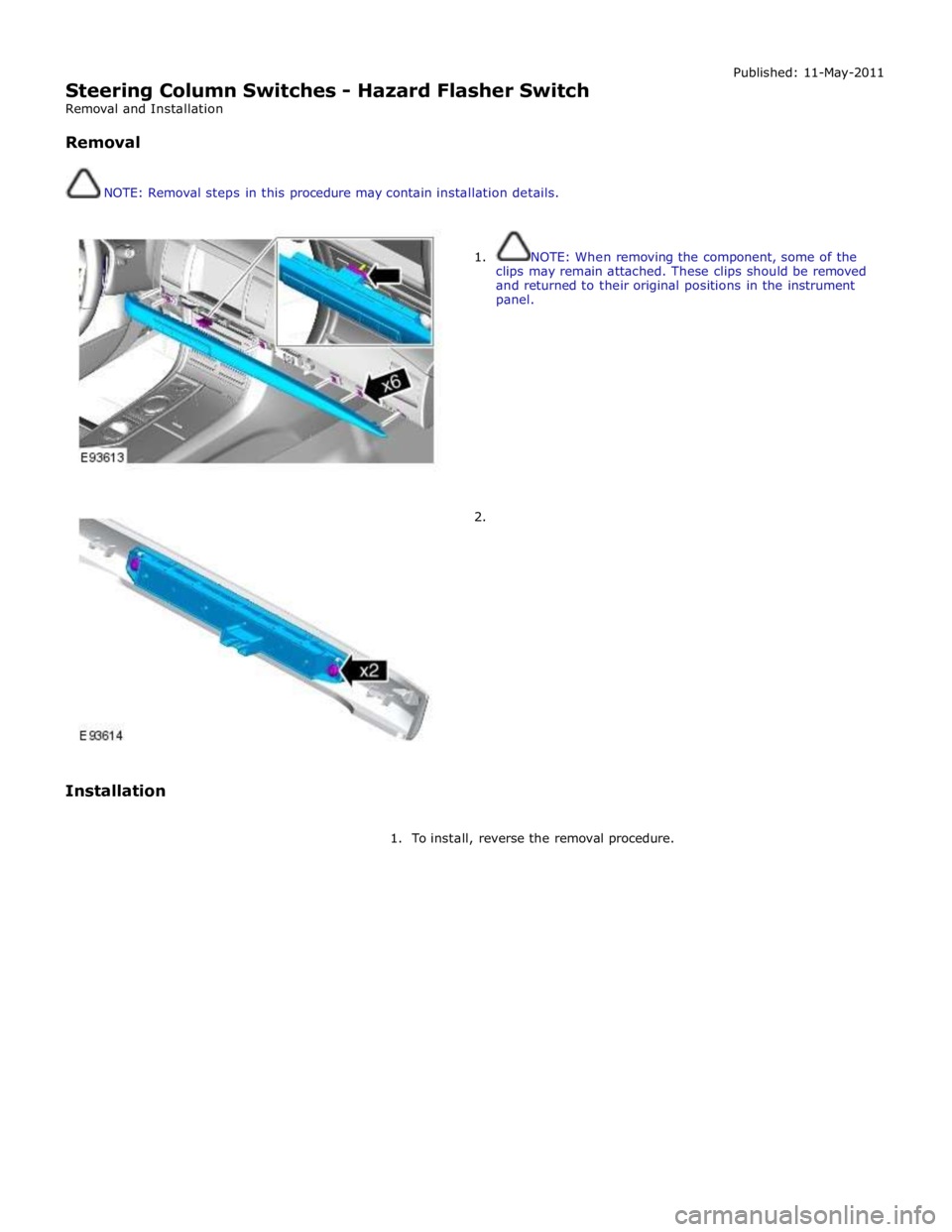
Steering Column Switches - Hazard Flasher Switch
Removal and Installation
Removal
NOTE: Removal steps in this procedure may contain installation details. Published: 11-May-2011
Installation
1. NOTE: When removing the component, some of the
clips may remain attached. These clips should be removed
and returned to their original positions in the instrument
panel.
2.
1. To install, reverse the removal procedure.
Page 1447 of 3039

DTC Description Possible Cause Action U0103-82
Lost Communication With
Gear Shift Control Module
A-alive / sequence counter
incorrect / not updated
Alive counter fault Check Transmission shift module for stored DTCs.
Check CAN Bus Circuit for fault U0103-83
Lost Communication With
Gear Shift Control Module A
- value of signal protection
calculation incorrect
Checksum fault Check Transmission shift module for stored DTCs.
Check CAN Bus Circuit for fault U0103-87
Lost Communication With
Gear Shift Control Module A
- missing message
CAN Timeout Check Transmission shift module for stored DTCs.
Check CAN Bus Circuit for fault U0122-82
Lost Communication With
Vehicle Dynamics Control
Module - alive / sequence
counter incorrect / not updated
Alive counter fault Check Anti-lock braking system for stored DTCs. Check
CAN Bus Circuit for fault U0122-83
Lost Communication With
Vehicle Dynamics Control
Module - value of signal
protection calculation
incorrect
Checksum fault Check Anti-lock braking system for stored DTCs. Check
CAN Bus Circuit for fault U0122-87
Lost Communication With
Vehicle Dynamics Control
Module - missing message
CAN Timeout Check Anti-lock braking system for stored DTCs. Check
CAN Bus Circuit for fault U0126-00
Lost Communication With
Steering Angle Sensor
Module - no sub type
information
Lost Communication
With Steering Angle
Sensor Module Check Steering angle sensor for stored DTCs. Check
CAN Bus Circuit for fault U0128-87
Lost Communication With
Park Brake Control Module -
missing message
CAN timeout electronic
parking brake module Check Electronic Parking Brake Module for stored DTCs.
Check CAN Bus Circuit for fault U0140-82
Lost Communication With
Body Control Module - alive / sequence counter incorrect / not updated
Alive counter fault Check Central junction box for stored DTCs. Check CAN
Bus Circuit for fault U0140-83
Lost Communication With
Body Control Module - value
of signal protection
calculation incorrect
Checksum fault Check Central junction box for stored DTCs. Check CAN
Bus Circuit for fault U0140-87
Lost Communication With
Body Control Module - missing message
CAN Timeout Check Central junction box for stored DTCs. Check CAN
Bus Circuit for fault U0155-87
Lost Communication With
Instrument Panel Cluster
(Instrument cluster) Control
Module - missing message
CAN timeout instrument
cluster Check Instrument cluster for stored DTCs. Check CAN
Bus Circuit for fault U0300-68
Control Module - event
information
Transmission software
does not match vehicle
network Check Central junction box software level, Check
Transmission control module Software level, Update
software as required using the manufacturer approved
process U0401-08
Invalid Data Received From
Engine control module/PCM
A - Bus Signal Message
Failures
Inaccurate engine speed,
torque information Check Engine control module for stored DTCs, Check
CAN Bus circuit for faults U0401-68
Invalid Data Received from
Engine control module/PCM
A - event information
Inaccurate engine speed,
torque information Check Engine control module for stored DTCs. Check
CAN Bus Circuit for fault U0401-86
Invalid Data Received from
Engine control module/PCM
A - Signal Invalid
Inaccurate engine speed,
torque information Check Engine control module for stored DTCs. Check
CAN Bus Circuit for fault U0404-68
Invalid Data Received from
Gear Shift Control Module A
- event information
Incorrect CAN data
received from
Transmission shift
module Check Transmission Shift Module for stored DTCs.
Refer to Circuit diagrams and check CAN and LIN Bus
for Circuit fault U0404-81
Invalid Data Received from
Gear Shift Control Module A
- Invalid Serial Data
Received
Incorrect LIN data
received from
Transmission shift
module Check Transmission Shift Module for stored DTCs.
Refer to Circuit diagrams and check CAN and LIN Bus
for Circuit fault www.JagDocs.com
Page 1648 of 3039

DTC Description Possible Causes Action C1A67-98 Forward Looking Sensor
- Component or system
over temperature
Speed control sensor
internal temperature
exceeded threshold
Allow system to cool. Note: This DTC will be cleared
automatically when environmental conditions allow P174E-81
Output Shaft
Speed/ABS Wheel
Speed Correlation -
Invalid serial data
received
Follow speed is
mis-calculated to too
high a value
Clear DTC and re-test U0001-88
High Speed CAN
Communication Bus -
Bus off
Vehicle CAN Bus off
condition
Carry out any pinpoint tests associated with this
DTC using the manufacturer approved diagnostic
system. Carry out CAN network integrity tests using
the manufacturer approved diagnostic system U0100-00
Lost Communications
With ECM/PCM "A" - No
sub type information
ECM missing message
Carry out any pinpoint tests associated with this
DTC using the manufacturer approved diagnostic
system. Check ECM for related DTCs and refer to the
relevant DTC Index U0101-00
Lost Communications
With TCM - No sub
type information
TCM missing message
Carry out any pinpoint tests associated with this
DTC using the manufacturer approved diagnostic
system. Check TCM for related DTCs and refer to the
relevant DTC Index U0103-00
Lost Communication
With Gear Shift Control
Module A - No sub type
information
No sub type information
Refer to the electrical circuit diagrams and check the
power and ground connections to the Transmission
Shift Module. Using the manufacturer approved
diagnostic system, complete a CAN network integrity
test. Refer to the electrical circuit diagrams and
check the CAN network between the Transmission
Shift Module and Speed Control Module U0103-87
Lost Communication
With Gear Shift Module
- Missing Message
Transmission shift
module missing message
Carry out any pinpoint tests associated with this
DTC using the manufacturer approved diagnostic
system. Check transmission shift module for related
DTCs and refer to the relevant DTC Index U0121-00
Lost Communication
With Anti-lock Brake
System (ABS) Control
Module - No sub type
information
ABS missing message
Carry out any pinpoint tests associated with this
DTC using the manufacturer approved diagnostic
system. Check ABS for related DTCs and refer to the
relevant DTC Index U0128-00
Lost Communications
With Park Brake Module
- No sub type
information
Parking brake missing
message
Carry out any pinpoint tests associated with this
DTC using the manufacturer approved diagnostic
system. Check parking brake module for related
DTCs and refer to the relevant DTC Index U0155-00
Lost Communications
With Instrument Panel
Cluster (IPC) Control
Module - No sub type
information
Instrument cluster
missing message
Carry out any pinpoint tests associated with this
DTC using the manufacturer approved diagnostic
system. Check instrument cluster for related DTCs
and refer to the relevant DTC Index U0300-00
Internal Control Module
Software
Incompatibility - No
sub type information
Invalid configuration
message is received
Re-configure the speed control module using the
manufacturer approved diagnostic system. Clear
DTCs and re-test. If DTC still logged, suspect
incorrect speed control module installed. Check and
install a new module as required, refer to new
module/component installation note at top of DTC
Index U0300-55
Internal Control Module
Software
Incompatibility - Not
configured
RJB - at least one of the
car configuration
parameters is not
configured
Re-configure the RJB using the manufacturer
approved diagnostic system www.JagDocs.com