instrument panel JAGUAR XFR 2010 1.G Workshop Manual
[x] Cancel search | Manufacturer: JAGUAR, Model Year: 2010, Model line: XFR, Model: JAGUAR XFR 2010 1.GPages: 3039, PDF Size: 58.49 MB
Page 2673 of 3039

Supplemental Restraint System - Side Air Curtain Module
Removal and Installation
Removal
NOTE: Removal steps in this procedure may contain installation details.
All vehicles Published: 19-May-2011
1. Make the air bag supplemental restraint system (SRS) safe.
Refer to: Standard Workshop Practices (100-00 General Information, Description and Operation).
2. Refer to: Battery Disconnect and Connect (414-01 Battery, Mounting and Cables, General Procedures).
3. Refer to: Interior Rear View Mirror (501-09 Rear View Mirrors, Removal and Installation).
4. Refer to: Overhead Console (501-12 Instrument Panel and Console, Removal and Installation).
5. Refer to: Sun Visor (501-05 Interior Trim and Ornamentation, Removal and Installation).
6. Refer to: A-Pillar Trim Panel (501-05 Interior Trim and Ornamentation, Removal and Installation).
7. Refer to: B-Pillar Upper Trim Panel (501-05 Interior Trim and Ornamentation, Removal and Installation).
8. Refer to: C-Pillar Lower Trim Panel (501-05 Interior Trim and Ornamentation, Removal and Installation).
9. Torque: 2 Nm
Page 2734 of 3039
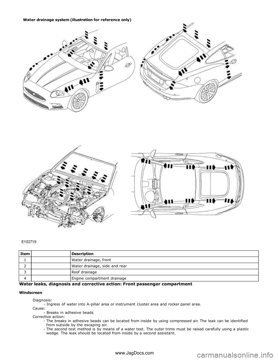
1
Water drainage, front 2
Water drainage, side and rear 3
Roof drainage 4
Engine compartment drainage Water leaks, diagnosis and corrective action: Front passenger compartment
Windscreen
Diagnosis:
- Ingress of water into A-pillar area or instrument cluster area and rocker panel area.
Cause:
- Breaks in adhesive beads
Corrective action:
- The breaks in adhesive beads can be located from inside by using compressed air. The leak can be identified
from outside by the escaping air.
- The second test method is by means of a water test. The outer trims must be raised carefully using a plastic
wedge. The leak should be located from inside by a second assistant. Water drainage system (illustration for reference only)
www.JagDocs.com
Page 2740 of 3039
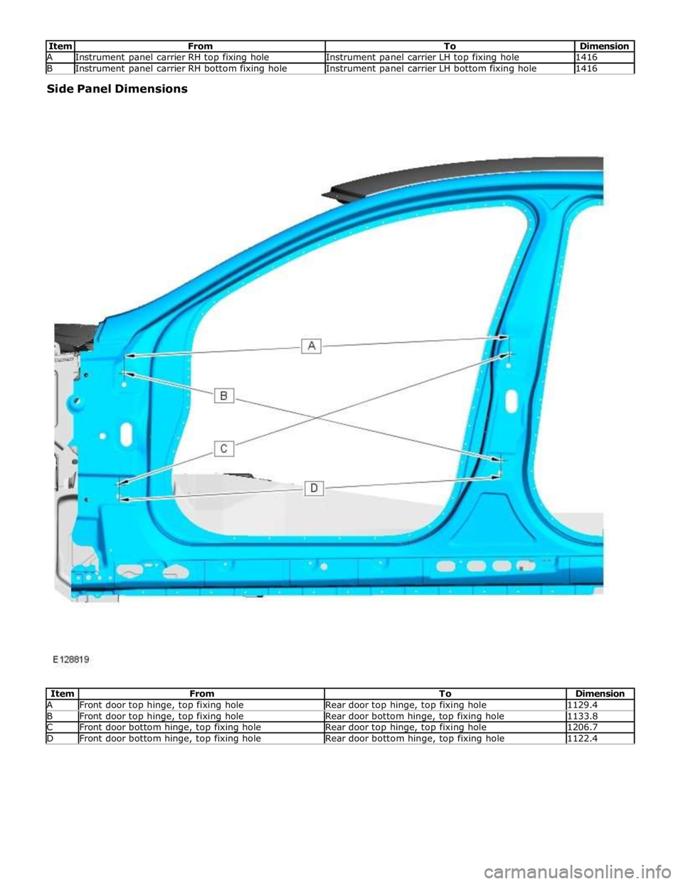
A Instrument panel carrier RH top fixing hole Instrument panel carrier LH top fixing hole 1416 B Instrument panel carrier RH bottom fixing hole Instrument panel carrier LH bottom fixing hole 1416 Side Panel Dimensions
Item From To Dimension A Front door top hinge, top fixing hole Rear door top hinge, top fixing hole 1129.4 B Front door top hinge, top fixing hole Rear door bottom hinge, top fixing hole 1133.8 C Front door bottom hinge, top fixing hole Rear door top hinge, top fixing hole 1206.7 D Front door bottom hinge, top fixing hole Rear door bottom hinge, top fixing hole 1122.4
Page 2754 of 3039
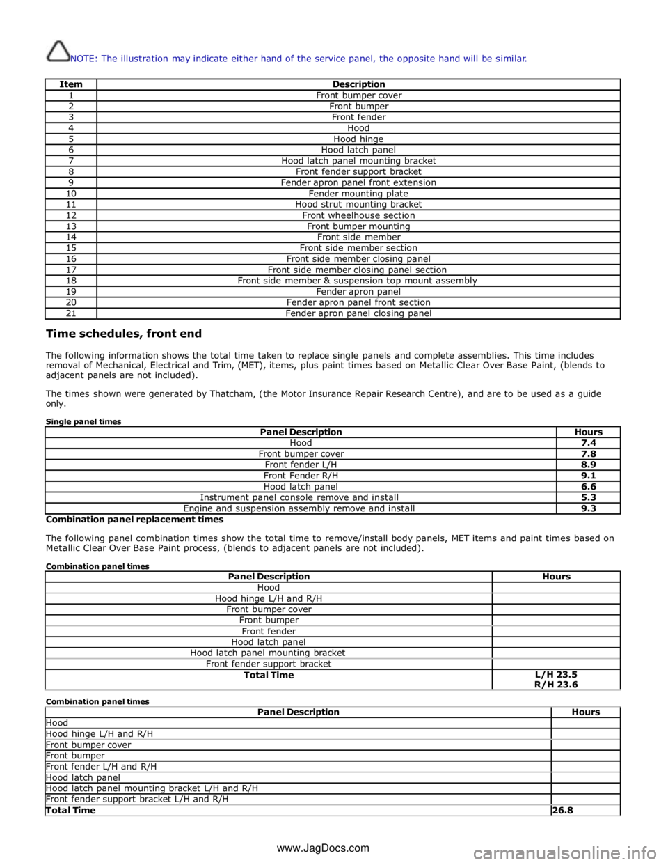
NOTE: The illustration may indicate either hand of the service panel, the opposite hand will be similar.
Item Description 1 Front bumper cover 2 Front bumper 3 Front fender 4 Hood 5 Hood hinge 6 Hood latch panel 7 Hood latch panel mounting bracket 8 Front fender support bracket 9 Fender apron panel front extension 10 Fender mounting plate 11 Hood strut mounting bracket 12 Front wheelhouse section 13 Front bumper mounting 14 Front side member 15 Front side member section 16 Front side member closing panel 17 Front side member closing panel section 18 Front side member & suspension top mount assembly 19 Fender apron panel 20 Fender apron panel front section 21 Fender apron panel closing panel Time schedules, front end
The following information shows the total time taken to replace single panels and complete assemblies. This time includes
removal of Mechanical, Electrical and Trim, (MET), items, plus paint times based on Metallic Clear Over Base Paint, (blends to
adjacent panels are not included).
The times shown were generated by Thatcham, (the Motor Insurance Repair Research Centre), and are to be used as a guide
only.
Single panel times
Panel Description Hours Hood 7.4 Front bumper cover 7.8 Front fender L/H 8.9 Front Fender R/H 9.1 Hood latch panel 6.6 Instrument panel console remove and install 5.3 Engine and suspension assembly remove and install 9.3 Combination panel replacement times
The following panel combination times show the total time to remove/install body panels, MET items and paint times based on
Metallic Clear Over Base Paint process, (blends to adjacent panels are not included).
Combination panel times
Panel Description Hours Hood Hood hinge L/H and R/H Front bumper cover Front bumper Front fender Hood latch panel Hood latch panel mounting bracket Front fender support bracket Total Time L/H 23.5
R/H 23.6 Combination panel times
Panel Description Hours Hood Hood hinge L/H and R/H Front bumper cover Front bumper Front fender L/H and R/H Hood latch panel Hood latch panel mounting bracket L/H and R/H Front fender support bracket L/H and R/H Total Time 26.8 www.JagDocs.com
Page 2755 of 3039

Hood Hood hinge L/H and R/H Front bumper cover Front bumper Front fender Hood latch panel Front fender support bracket Fender apron panel Fender apron panel closing panel Front side member & suspension top mount assembly Fender mounting plate Front fender lower mounting Engine and suspension assembly remove and install Instrument panel console remove and install Total Time L/H 44.3
R/H 44.5 Combination panel times
Panel Description Hours Hood Hood hinge L/H and R/H Front bumper cover Front bumper Front fender L/H and R/H Hood latch panel Front fender support bracket L/H and R/H Fender apron panel L/H and R/H Fender apron panel closing panel L/H and R/H Front side member & suspension top mount assembly L/H and R/H Fender mounting plate L/H and R/H Front fender lower mounting L/H and R/H Engine and suspension assembly remove and install Instrument panel console remove and install Total Time 57.6 Combination panel times
Panel Description Hours Hood Hood hinge L/H and R/H Front bumper cover Front bumper Front fender Hood latch panel Front fender support bracket Front bumper mounting Front side member section Front side member closing panel section Total Time L/H 28.0
R/H 28.1 Combination panel times
Panel Description Hours Hood Hood hinge L/H and R/H Front bumper cover Front bumper Front fender Hood latch panel Front fender support bracket Front fender support bracket mounting Front fender lower mounting Front bumper mounting Front side member Front side member closing panel Front wheelhouse section Engine and suspension assembly remove and install Total Time L/H 37.6
R/H 37.4
Page 2843 of 3039
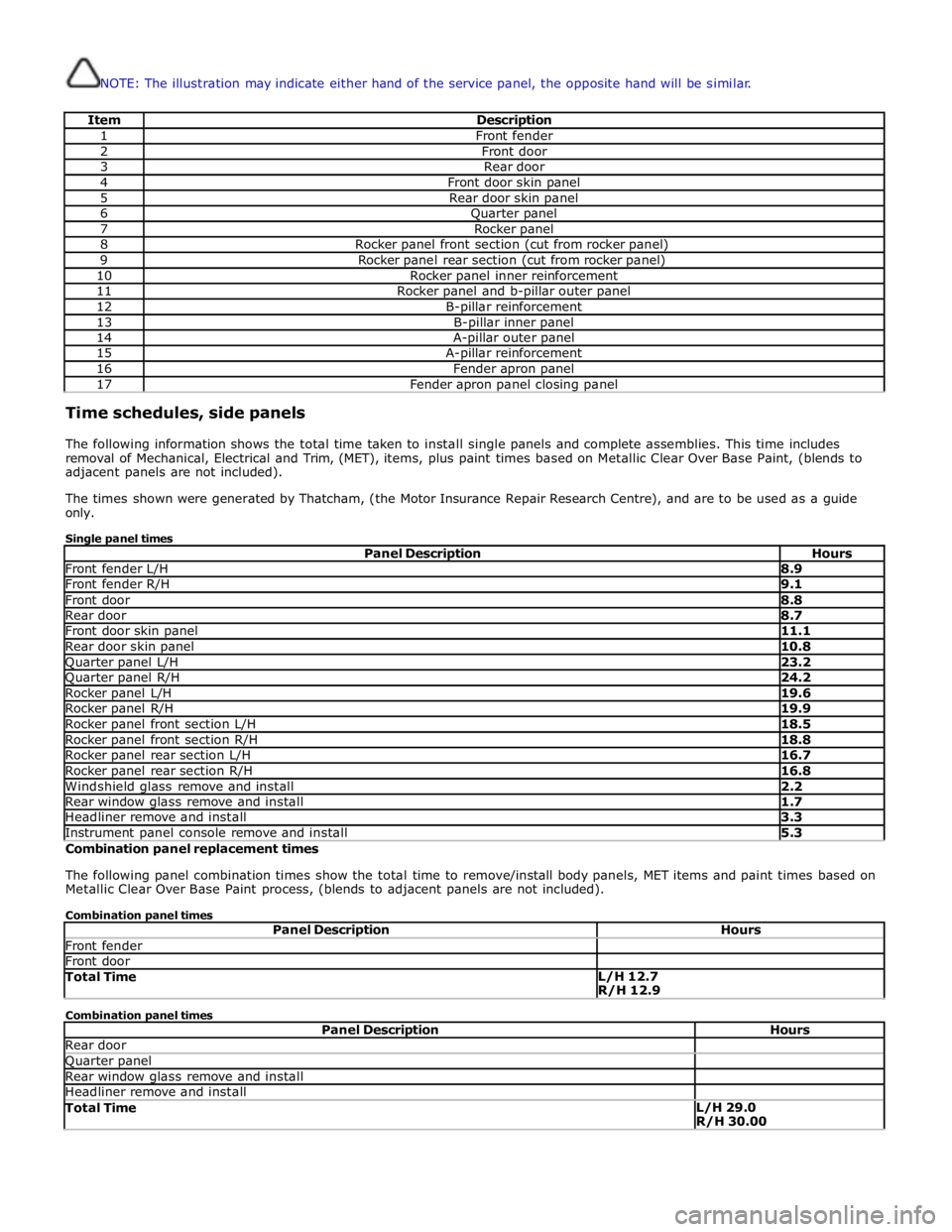
NOTE: The illustration may indicate either hand of the service panel, the opposite hand will be similar.
Item Description 1 Front fender 2 Front door 3 Rear door 4 Front door skin panel 5 Rear door skin panel 6 Quarter panel 7 Rocker panel 8 Rocker panel front section (cut from rocker panel) 9 Rocker panel rear section (cut from rocker panel) 10 Rocker panel inner reinforcement 11 Rocker panel and b-pillar outer panel 12 B-pillar reinforcement 13 B-pillar inner panel 14 A-pillar outer panel 15 A-pillar reinforcement 16 Fender apron panel 17 Fender apron panel closing panel Time schedules, side panels
The following information shows the total time taken to install single panels and complete assemblies. This time includes
removal of Mechanical, Electrical and Trim, (MET), items, plus paint times based on Metallic Clear Over Base Paint, (blends to
adjacent panels are not included).
The times shown were generated by Thatcham, (the Motor Insurance Repair Research Centre), and are to be used as a guide
only.
Single panel times
Panel Description Hours Front fender L/H 8.9 Front fender R/H 9.1 Front door 8.8 Rear door 8.7 Front door skin panel 11.1 Rear door skin panel 10.8 Quarter panel L/H 23.2 Quarter panel R/H 24.2 Rocker panel L/H 19.6 Rocker panel R/H 19.9 Rocker panel front section L/H 18.5 Rocker panel front section R/H 18.8 Rocker panel rear section L/H 16.7 Rocker panel rear section R/H 16.8 Windshield glass remove and install 2.2 Rear window glass remove and install 1.7 Headliner remove and install 3.3 Instrument panel console remove and install 5.3 Combination panel replacement times
The following panel combination times show the total time to remove/install body panels, MET items and paint times based on
Metallic Clear Over Base Paint process, (blends to adjacent panels are not included).
Combination panel times
Panel Description Hours Front fender Front door Total Time L/H 12.7
R/H 12.9 Combination panel times
Panel Description Hours Rear door Quarter panel Rear window glass remove and install Headliner remove and install Total Time L/H 29.0
R/H 30.00
Page 2844 of 3039
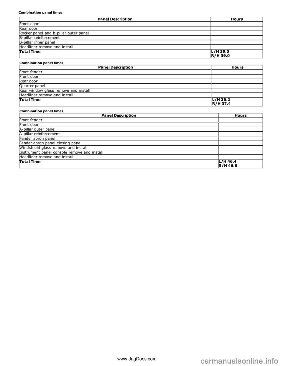
Front door Rear door Rocker panel and b-pillar outer panel B-pillar reinforcement B-pillar inner panel Headliner remove and install Total Time L/H 39.0
R/H 39.0 Combination panel times
Panel Description Hours Front fender Front door Rear door Quarter panel Rear window glass remove and install Headliner remove and install Total Time L/H 36.2
R/H 37.4 Combination panel times
Panel Description Hours Front fender Front door A-pillar outer panel A-pillar reinforcement Fender apron panel Fender apron panel closing panel Windshield glass remove and install Instrument panel console remove and install Headliner remove and install Total Time L/H 46.4
R/H 46.6 www.JagDocs.com
Page 2845 of 3039
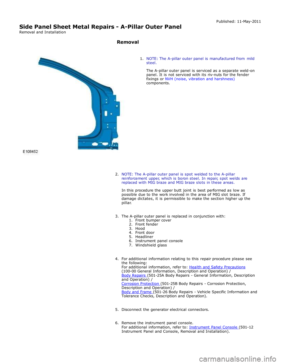
(100-00 General Information, Description and Operation) /
Body Repairs (501-25A Body Repairs - General Information, Description and Operation) /
Corrosion Protection (501-25B Body Repairs - Corrosion Protection, Description and Operation) /
Body and Frame (501-26 Body Repairs - Vehicle Specific Information and Tolerance Checks, Description and Operation).
5. Disconnect the generator electrical connectors.
6. Remove the instrument panel console.
For additional information, refer to: Instrument Panel Console (501-12 Instrument Panel and Console, Removal and Installation).