instrument panel JAGUAR XFR 2010 1.G Service Manual
[x] Cancel search | Manufacturer: JAGUAR, Model Year: 2010, Model line: XFR, Model: JAGUAR XFR 2010 1.GPages: 3039, PDF Size: 58.49 MB
Page 1746 of 3039
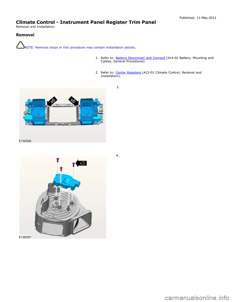
Climate Control - Instrument Panel Register Trim Panel
Removal and Installation
Removal
NOTE: Removal steps in this procedure may contain installation details. Published: 11-May-2011
1. Refer to: Battery Disconnect and Connect (414-01 Battery, Mounting and Cables, General Procedures).
2. Refer to: Center Registers (412-01 Climate Control, Removal and Installation).
3.
4.
Page 1750 of 3039
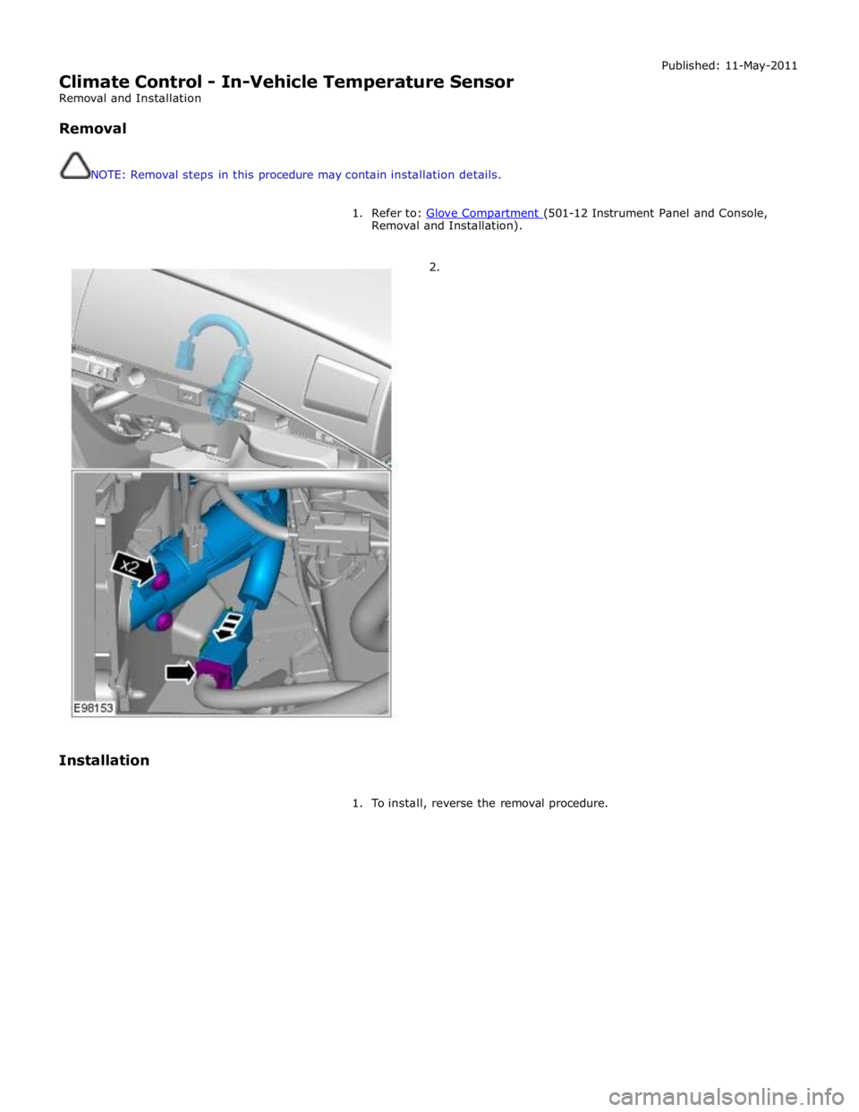
Climate Control - In-Vehicle Temperature Sensor
Removal and Installation
Removal
NOTE: Removal steps in this procedure may contain installation details. Published: 11-May-2011
1. Refer to: Glove Compartment (501-12 Instrument Panel and Console, Removal and Installation).
2.
Installation
1. To install, reverse the removal procedure.
Page 1757 of 3039
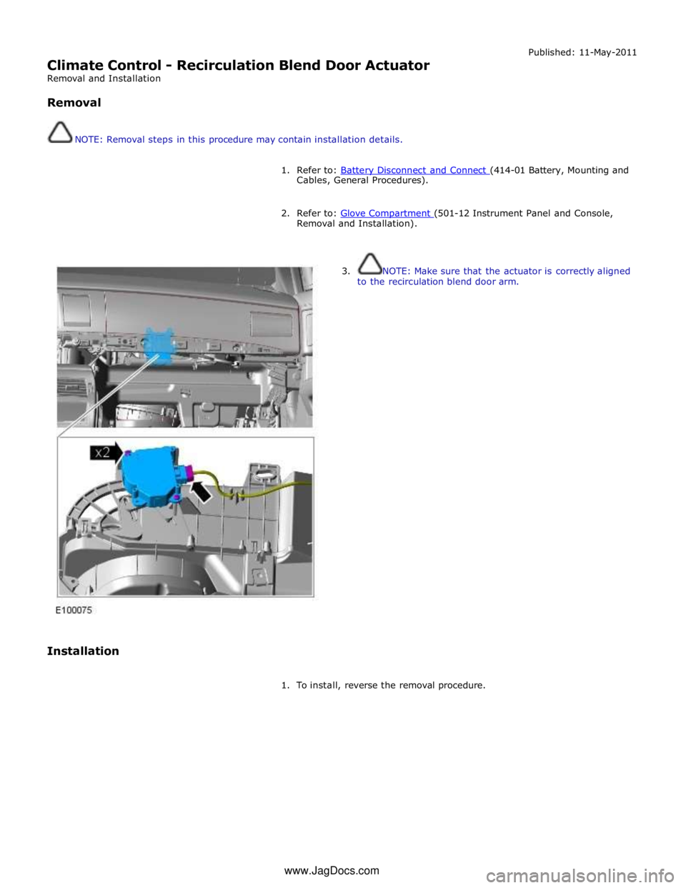
Climate Control - Recirculation Blend Door Actuator
Removal and Installation
Removal
NOTE: Removal steps in this procedure may contain installation details. Published: 11-May-2011
1. Refer to: Battery Disconnect and Connect (414-01 Battery, Mounting and Cables, General Procedures).
2. Refer to: Glove Compartment (501-12 Instrument Panel and Console, Removal and Installation).
Installation
3. NOTE: Make sure that the actuator is correctly aligned
to the recirculation blend door arm.
1. To install, reverse the removal procedure. www.JagDocs.com
Page 1766 of 3039
Published: 11-May-2011
Auxiliary Climate Control - Electric Booster Heater - System Operation and
Component Description
Description and Operation
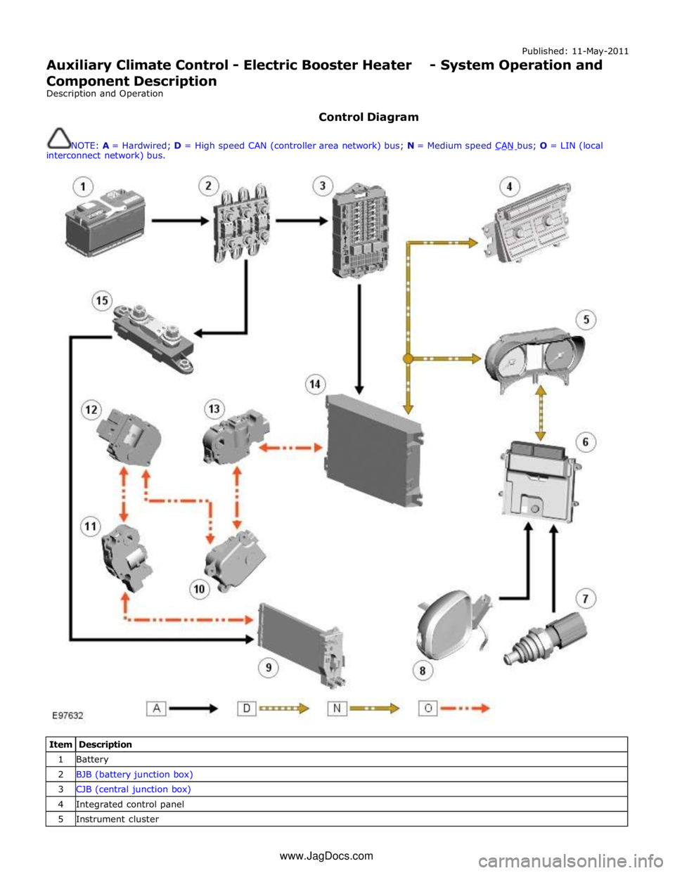
Control Diagram
NOTE: A = Hardwired; D = High speed CAN (controller area network) bus; N = Medium speed CAN bus; O = LIN (local interconnect network) bus.
Item Description 1 Battery 2 BJB (battery junction box) 3 CJB (central junction box) 4 Integrated control panel 5 Instrument cluster www.JagDocs.com
Page 1770 of 3039
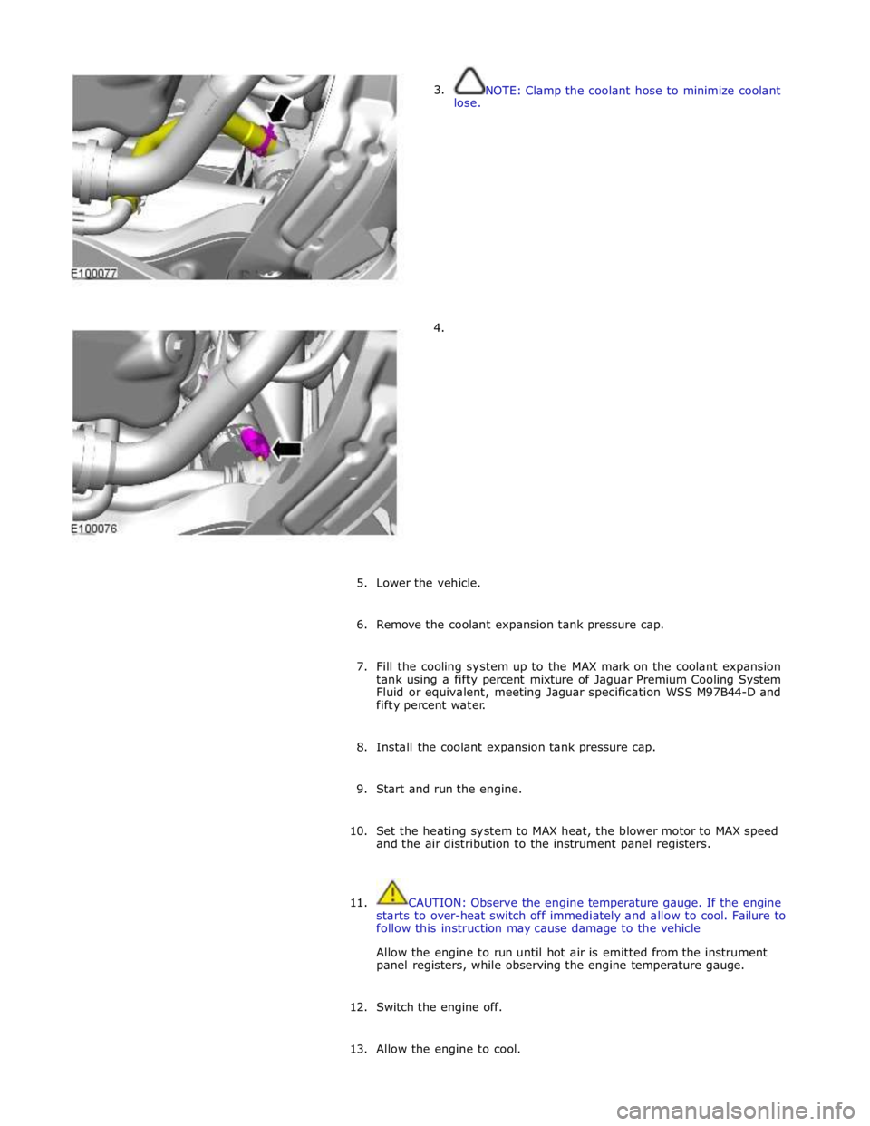
3.
lose.
4. NOTE: Clamp the coolant hose to minimize coolant
5. Lower the vehicle.
6. Remove the coolant expansion tank pressure cap.
7. Fill the cooling system up to the MAX mark on the coolant expansion
tank using a fifty percent mixture of Jaguar Premium Cooling System
Fluid or equivalent, meeting Jaguar specification WSS M97B44-D and
fifty percent water.
8. Install the coolant expansion tank pressure cap.
9. Start and run the engine.
10. Set the heating system to MAX heat, the blower motor to MAX speed
and the air distribution to the instrument panel registers.
11. CAUTION: Observe the engine temperature gauge. If the engine
starts to over-heat switch off immediately and allow to cool. Failure to
follow this instruction may cause damage to the vehicle
Allow the engine to run until hot air is emitted from the instrument
panel registers, while observing the engine temperature gauge.
12. Switch the engine off.
13. Allow the engine to cool.
Page 1797 of 3039
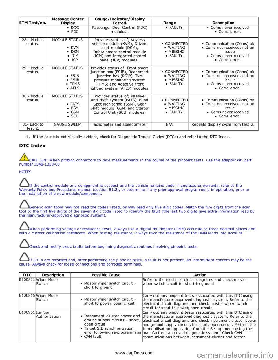
ETM Test/no. Message Center Display Gauge/Indicator/Display
Tested.
Range
Description DDC
PDC Passenger Door Control (PDC)
modules.. FAULTY.
Coms never received
Coms error . 28 - Module MODULE STATUS. Provides status of; Keyless
CONNECTED
Communication (Coms) ok status. vehicle module (KVM), Drivers KVM
seat module (DSM), WAITING Coms not received, not an DSM
Infotainment control module MISSING issue ICM
(ICM) and Integrated control FAULTY. Coms never received ICP
panel (ICP) modules.. Coms error . 29 - Module MODULE STATUS. Provides status of; Front smart
CONNECTED
Communication (Coms) ok status. junction box (FSJB), Rear smart FSJB
junction box (RSJB), Tyre WAITING Coms not received, not an RSJB
pressure monitoring system MISSING issue TPMS
(TPMS) and Adaptive front FAULTY. Coms never received AFLS
lighting system (AFLS) modules. Coms error . 30 - Module MODULE STATUS. Provides status of; Passive
CONNECTED
Communication (Coms) ok status. anti-theft system (PATS), Blind PATS
Spot Monitoring (BSM), Gear WAITING Coms not received, not an BSM
shift module (GSM) and Starter MISSING issue GSM
Control Unit (SCU) modules. FAULTY. Coms never received SCU Coms error . 31- Back to
test 2. GAUGE SWEEP. Tachometer and speedometer. N/A. Repeats display cycle from test 2.
1. If the cause is not visually evident, check for Diagnostic Trouble Codes (DTCs) and refer to the DTC Index.
DTC Index
CAUTION: When probing connectors to take measurements in the course of the pinpoint tests, use the adaptor kit, part
number 3548-1358-00
NOTES:
If the control module or a component is suspect and the vehicle remains under manufacturer warranty, refer to the
Warranty Policy and Procedures manual (section B1.2), or determine if any prior approval programme is in operation, prior to
the installation of a new module/component.
Generic scan tools may not read the codes listed, or may read only five digit codes. Match the five digits from the scan
tool to the first five digits of the seven digit code listed to identify the fault (the last two digits give extra information read by
the manufacturer-approved diagnostic system).
When performing voltage or resistance tests, always use a digital multimeter (DMM) accurate to three decimal places and
with a current calibration certificate. When testing resistance, always take the resistance of the DMM leads into account.
Check and rectify basic faults before beginning diagnostic routines involving pinpoint tests.
If DTCs are recorded and, after performing the pinpoint tests, a fault is not present, an intermittent concern may be the
cause. Always check for loose connections and corroded terminals.
DTC Description Possible Cause Action B100811
Wiper Mode
Switch
Master wiper switch circuit -
short to ground Refer to the electrical circuit diagrams and check master
wiper switch circuit for short to ground B100815
Wiper Mode
Switch
Master wiper switch circuit -
short to power, open circuit Carry out any pinpoint tests associated with this DTC using
the manufacturer approved diagnostic system. Refer to the
electrical circuit diagrams and check master wiper switch
circuit for short to power, open circuit B100951
Ignition
Authorisation
Instrument cluster power and
ground supply circuits - short,
open circuit
Target SID synchronization
error following re-programming
CAN fault Carry out any pinpoint tests associated with this DTC using
the manufacturer approved diagnostic system. Refer to the
electrical circuit diagrams and check instrument cluster power
and ground supply circuits for short, open circuit. Perform the
Immobilisation application from the Set-up menu using the
manufacturer approved diagnostic system. Check CAN
communications between instrument cluster and tester www.JagDocs.com
Page 1805 of 3039

DTC Description Possible Cause Action U013900
Lost
Communication
with Suspension
Control Module 'B'
Loss of CAN communication
with adaptive damping module Carry out any pinpoint tests associated with this DTC using
the manufacturer approved diagnostic system. Check
adaptive damping module for DTCs and refer to the relevant
DTC Index U014000
Lost
Communication
With Body
Control Module
Loss of CAN communication
with CJB Carry out any pinpoint tests associated with this DTC using
the manufacturer approved diagnostic system. Check CJB for
DTCs and refer to the relevant DTC Index U014200
Lost
Communication
With Body
Control Module
"B"
Loss of CAN communication
with RJB Carry out any pinpoint tests associated with this DTC using
the manufacturer approved diagnostic system. Check RJB for
DTCs and refer to the relevant DTC Index U015100
Lost
Communication
With Restraints
Control Module
Loss of CAN communication
with RCM Carry out any pinpoint tests associated with this DTC using
the manufacturer approved diagnostic system. Check RCM for
DTCs and refer to the relevant DTC Index U015600
Lost
Communication
with Information
Centre 'A'
Loss of CAN communication
with information and
entertainment control module Carry out any pinpoint tests associated with this DTC using
the manufacturer approved diagnostic system. Check
information and entertainment control module for DTCs and
refer to the relevant DTC Index U016400
Lost
Communication
with HVAC
Control Module
Loss of CAN communication
with climate control module Carry out any pinpoint tests associated with this DTC using
the manufacturer approved diagnostic system. Check climate
control module for DTCs and refer to the relevant DTC Index U019900
Lost
Communication
with Door Control
Module 'A'
Loss of CAN communication
with driver door module (DDM) Carry out any pinpoint tests associated with this DTC using
the manufacturer approved diagnostic system. Check DDM for
DTCs and refer to the relevant DTC Index U020000
Lost
Communication
with Door Control
Module 'B'
Loss of CAN communication
with passenger door module
(PDM) Carry out any pinpoint tests associated with this DTC using
the manufacturer approved diagnostic system. Check PDM for
DTCs and refer to the relevant DTC Index U020800
Lost
Communication
with Seat Control
Module 'A'
Loss of CAN communication
with driver seat module (DSM) Carry out any pinpoint tests associated with this DTC using
the manufacturer approved diagnostic system. Check DSM for
DTCs and refer to the relevant DTC Index U021400
Lost
Communication
with Remote
Function
Actuation
Loss of CAN communication
with keyless vehicle module
(KVM) Carry out any pinpoint tests associated with this DTC using
the manufacturer approved diagnostic system. Check KVM for
DTCs and refer to the relevant DTC Index U024100
Lost
Communication
with Headlamp
Control Module 'A'
Loss of CAN communication
with headlamp control module Carry out any pinpoint tests associated with this DTC using
the manufacturer approved diagnostic system. Check
headlamp control module for DTCs and refer to the relevant
DTC Index U025000
Lost
Communication
with Impact
Classification System Module
Loss of CAN communication
with pedestrian protection
module Carry out any pinpoint tests associated with this DTC using
the manufacturer approved diagnostic system. Check
pedestrian protection module for DTCs and refer to the
relevant DTC Index U025600
Lost
Communication
with Front
Controls Interface
Module 'A'
Loss of CAN communication
with integrated control panel Carry out any pinpoint tests associated with this DTC using
the manufacturer approved diagnostic system. Check
integrated control panel for DTCs and refer to the relevant
DTC Index U030000
Internal Control
Module Software
Incompatibility
Invalid configuration message
is received Re-configure the RJB using the manufacturer approved
diagnostic system. Clear the DTC and retest. If the DTC is
still logged suspect the instrument cluster, refer to the new
module/component installation note at the top of the DTC
Index U040268
Invalid data
received from
TCM
Algorithm based failures -
events information Check TCM for DTCs and refer to the relevant DTC Index U200411
Auxiliary Switch
Pack
Auxiliary switch signal circuit -
short to ground Refer to the electrical circuit diagrams and check auxiliary
switch signal circuit for short to ground U200415
Auxiliary Switch
Pack
Auxiliary switch signal circuit -
short to power, open circuit Carry out any pinpoint tests associated with this DTC using
the manufacturer approved diagnostic system. Refer to the
electrical circuit diagrams and check auxiliary switch signal
circuit for short to power, open circuit
Page 1821 of 3039
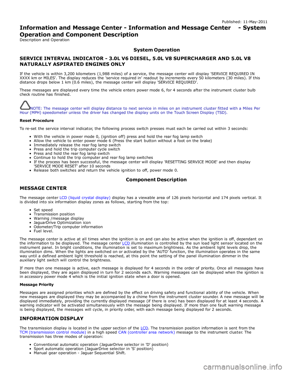
Published: 11-May-2011
Information and Message Center - Information and Message Center - System
Operation and Component Description
Description and Operation
System Operation
SERVICE INTERVAL INDICATOR - 3.0L V6 DIESEL, 5.0L V8 SUPERCHARGER AND 5.0L V8 NATURALLY ASPIRATED ENGINES ONLY
If the vehicle is within 3,200 kilometers (1,988 miles) of a service, the message center will display 'SERVICE REQUIRED IN
XXXX km or MILES'. The display reduces the 'service required in' readout by increments every 50 kilometers (30 miles). If this
distance drops below 1 km (0.6 miles), the message center will display 'SERVICE REQUIRED'.
These messages are displayed every time the vehicle enters power mode 6, for 4 seconds after the instrument cluster bulb
check routine has finished.
NOTE: The message center will display distance to next service in miles on an instrument cluster fitted with a Miles Per
Hour (MPH) speedometer unless the driver has changed the display units on the Touch Screen Display (TSD).
Reset Procedure
To re-set the service interval indicator, the following process switch presses must each be carried out within 3 seconds:
With the vehicle in power mode 0, (ignition off) press and hold the rear fog lamp switch
Allow the vehicle to enter power mode 6 (Press the start button without a foot on the brake)
Immediately release the rear fog lamp switch
Press and hold the trip computer cycle switch
Press and hold the rear fog lamp switch
Continue to hold the trip computer and rear fog lamp switches
If the process has been successful, the message center will display 'RESETTING SERVICE MODE' and then display
'SERVICE MODE RESET' after 10 seconds
Release both switches and return the vehicle ignition to off, power mode 0.
MESSAGE CENTER Component Description
The message center LCD (liquid crystal display) display has a viewable area of 126 pixels horizontal and 174 pixels vertical. It
is divided into six information display zones as follows, starting from the top:
Set speed
Transmission position
Warning /message display
JaguarDrive Optimization icon
Odometer/Trip computer information
Fuel level.
The message center is active at all times when the ignition is on and can also be active when the ignition is off, dependant on
the information to be displayed. The message center LCD illumination is controlled by the sun load light sensor located on the instrument panel. In bright conditions, the illumination is set to maximum brightness. As the ambient light levels drop, the
illumination dims. When the lights are switched on or activated by the 'AUTO' function, the illumination operates in the same
way until a defined ambient light threshold is reached, at this point the setting of the panel illumination dimmer in the
auxiliary light switch will control the brightness.
If more than one message is active, each message is displayed for 4 seconds in the order of priority. Once all messages have
been displayed, they are again displayed in turn for 2 seconds each. Warning messages can be displayed when the ignition is
in accessory power mode 4 which is the initial ignition state when a door is opened.
Message Priority
Messages are assigned priorities which are defined by the effect on driving safety and functional ability of the vehicle. When
new messages are displayed they may be accompanied by a chime from the instrument cluster sounder. A new message will be
displayed immediately, providing the currently displayed message (if there is one) has been displayed for at least 4 seconds. A
warning indicator will be activated simultaneously with the message being displayed. If more than one fault warning message
is being displayed, the messages will cycle, in priority order, with each message being displayed for 2 seconds.
INFORMATION DISPLAY
The transmission display is located in the upper section of the LCD. The transmission position information is sent from the TCM (transmission control module) in a high speed CAN (controller area network) message to the instrument cluster. The
transmission has three modes of operation:
Conventional automatic operation (JaguarDrive selector in 'D' position)
Sport automatic operation (JaguarDrive selector in 'S' position)
Manual gear operation - Jaguar Sequential Shift.
Page 1838 of 3039

Generic scan tools may not read the codes listed, or may read only five digit codes. Match the five digits from the scan
tool to the first five digits of the seven digit code listed to identify the fault (the last two digits give additional information
read by the manufacturer approved diagnostic system).
When performing voltage or resistance tests, always use a digital multimeter (DMM) accurate to three decimal places,
and with an up-to-date calibration certificate. When testing resistance always take the resistance of the DMM leads into
account.
Check and rectify basic faults before beginning diagnostic routines involving pinpoint tests.
Inspect connectors for signs of water ingress, and pins for damage and/or corrosion.
If DTCs are recorded and, after performing the pinpoint tests, a fault is not present, an intermittent concern may be the
cause. Always check for loose connections and corroded terminals.
When carrying out repair/diagnosis of the system, on removal of the front or rear bumper inspect the sensor connectors
to ensure they were correctly latched and check fly leads for signs of chaffing or trapped wires.
Check DDW for open campaigns. Refer to the corresponding bulletins and SSMs which may be valid for the specific
customer complaint and carry out the recommendations as required
DTC Description Possible Causes Action B11C911
Driver Display
Status LED
Driver Display Status LED
circuit - short to ground Refer to the electrical circuit diagrams and check driver display
status LED circuit for short to ground B11C915
Driver Display
Status LED
Driver Display Status LED
circuit - short to power,
open circuit Refer to the electrical circuit diagrams and check driver display
status LED circuit for short to power, open circuit B11D611
Driver Display Alert
LED
Driver Display Alert LED
circuit - short to ground Refer to the electrical circuit diagrams and check driver display
alert LED circuit for short to ground B11D615
Driver Display Alert
LED
Driver Display Alert LED
circuit - short to power,
open circuit Refer to the electrical circuit diagrams and check driver display
alert LED circuit for short to power, open circuit U001000
Medium Speed CAN
Communication Bus
No sub type information Carry out any pinpoint tests associated with this DTC using
the manufacturer approved diagnostic system. Check MS CAN
bus state, carry out CAN network integrity tests using the
manufacturer approved diagnostic system U014000
Lost
Communication
With Body Control
Module
Lost communication with
CJB Carry out any pinpoint tests associated with this DTC using
the manufacturer approved diagnostic system. Check CJB for
related DTCs and correct function, refer to the relevant DTC
Index U014200
Lost
Communication
With Body Control
Module "B"
Lost communication with
RJB Carry out any pinpoint tests associated with this DTC using
the manufacturer approved diagnostic system. Check RJB for
related DTCs and correct function, refer to the relevant DTC
Index U014600
Lost
Communication
With Gateway "A"
Lost communication with
information and
entertainment module Carry out any pinpoint tests associated with this DTC using
the manufacturer approved diagnostic system. Check
information and entertainment module for related DTCs and
correct function, refer to the relevant DTC Index U015500
Lost
Communication
With Instrument
Panel Cluster (IPC)
Control Module
Lost communication with
instrument cluster Carry out any pinpoint tests associated with this DTC using
the manufacturer approved diagnostic system. Check
instrument cluster for related DTCs and correct function, refer
to the relevant DTC Index U023200
Lost
Communication
With Side Obstacle
Detection Control
Module - Left
CAN bus circuit fault
Harness fault between left
side mirror and left side
module
Refer to the electrical circuit diagrams and check the
power and ground connections to the module. Using
the manufacturer approved diagnostic system,
complete a CAN network integrity test. Refer to the
electrical circuit diagrams and check the CAN network
between the left Blind Spot Monitoring System Module
and the right Blind Spot Monitoring System Module
Page 1839 of 3039
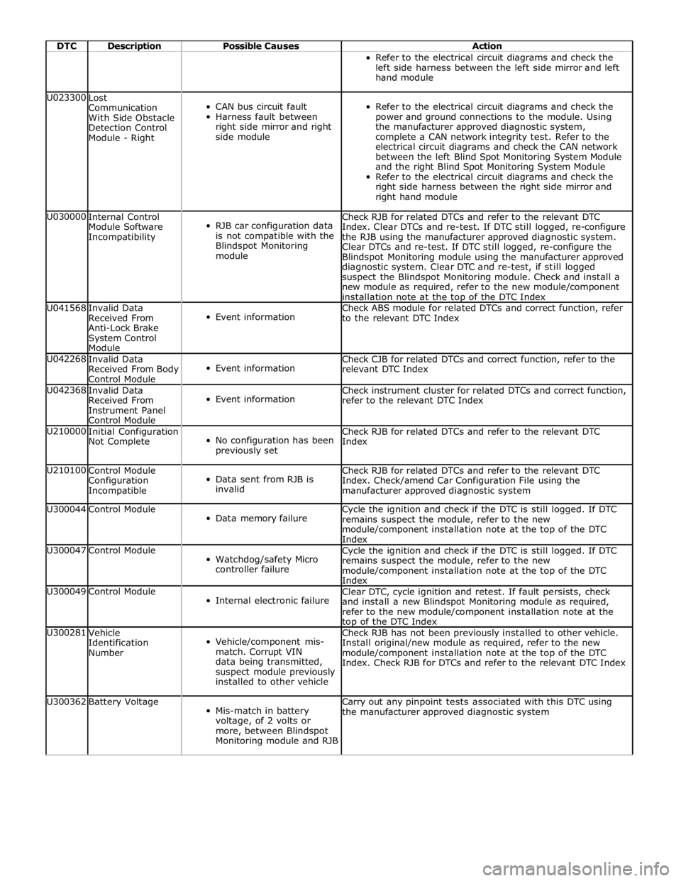
DTC Description Possible Causes Action Refer to the electrical circuit diagrams and check the
left side harness between the left side mirror and left
hand module U023300
Lost
Communication
With Side Obstacle
Detection Control
Module - Right
CAN bus circuit fault
Harness fault between
right side mirror and right
side module
Refer to the electrical circuit diagrams and check the
power and ground connections to the module. Using
the manufacturer approved diagnostic system,
complete a CAN network integrity test. Refer to the
electrical circuit diagrams and check the CAN network
between the left Blind Spot Monitoring System Module
and the right Blind Spot Monitoring System Module
Refer to the electrical circuit diagrams and check the
right side harness between the right side mirror and
right hand module U030000
Internal Control
Module Software
Incompatibility
RJB car configuration data
is not compatible with the
Blindspot Monitoring
module Check RJB for related DTCs and refer to the relevant DTC
Index. Clear DTCs and re-test. If DTC still logged, re-configure
the RJB using the manufacturer approved diagnostic system.
Clear DTCs and re-test. If DTC still logged, re-configure the
Blindspot Monitoring module using the manufacturer approved
diagnostic system. Clear DTC and re-test, if still logged
suspect the Blindspot Monitoring module. Check and install a
new module as required, refer to the new module/component
installation note at the top of the DTC Index U041568
Invalid Data
Received From
Anti-Lock Brake
System Control
Module
Event information Check ABS module for related DTCs and correct function, refer
to the relevant DTC Index U042268
Invalid Data
Received From Body
Control Module
Event information Check CJB for related DTCs and correct function, refer to the
relevant DTC Index U042368
Invalid Data
Received From
Instrument Panel
Control Module
Event information Check instrument cluster for related DTCs and correct function,
refer to the relevant DTC Index U210000
Initial Configuration
Not Complete
No configuration has been
previously set Check RJB for related DTCs and refer to the relevant DTC
Index U210100
Control Module
Configuration
Incompatible
Data sent from RJB is
invalid Check RJB for related DTCs and refer to the relevant DTC
Index. Check/amend Car Configuration File using the
manufacturer approved diagnostic system U300044 Control Module
Data memory failure Cycle the ignition and check if the DTC is still logged. If DTC
remains suspect the module, refer to the new
module/component installation note at the top of the DTC
Index U300047 Control Module
Watchdog/safety Micro
controller failure Cycle the ignition and check if the DTC is still logged. If DTC
remains suspect the module, refer to the new
module/component installation note at the top of the DTC
Index U300049 Control Module
Internal electronic failure Clear DTC, cycle ignition and retest. If fault persists, check
and install a new Blindspot Monitoring module as required,
refer to the new module/component installation note at the top of the DTC Index U300281
Vehicle
Identification
Number
Vehicle/component mis-
match. Corrupt VIN
data being transmitted,
suspect module previously
installed to other vehicle Check RJB has not been previously installed to other vehicle.
Install original/new module as required, refer to the new
module/component installation note at the top of the DTC
Index. Check RJB for DTCs and refer to the relevant DTC Index U300362 Battery Voltage
Mis-match in battery
voltage, of 2 volts or
more, between Blindspot
Monitoring module and RJB Carry out any pinpoint tests associated with this DTC using
the manufacturer approved diagnostic system