reset JAGUAR XFR 2010 1.G Owner's Manual
[x] Cancel search | Manufacturer: JAGUAR, Model Year: 2010, Model line: XFR, Model: JAGUAR XFR 2010 1.GPages: 3039, PDF Size: 58.49 MB
Page 1826 of 3039
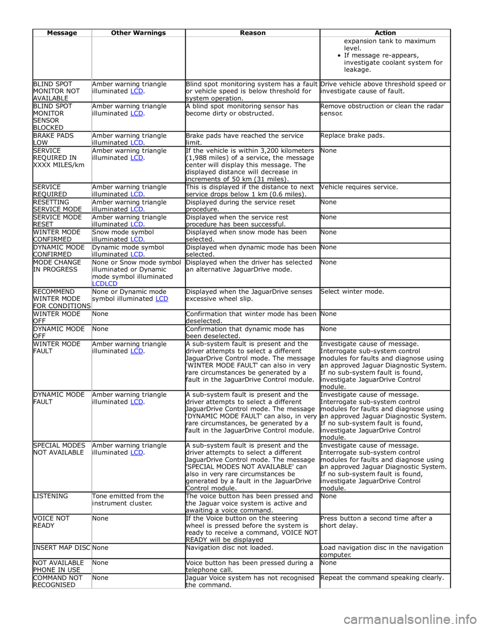
Message Other Warnings Reason Action expansion tank to maximum
level.
If message re-appears,
investigate coolant system for
leakage. BLIND SPOT
MONITOR NOT
AVAILABLE Amber warning triangle
illuminated LCD. Blind spot monitoring system has a fault
or vehicle speed is below threshold for system operation. Drive vehicle above threshold speed or
investigate cause of fault. BLIND SPOT
MONITOR
SENSOR
BLOCKED Amber warning triangle
illuminated LCD. A blind spot monitoring sensor has
become dirty or obstructed. Remove obstruction or clean the radar
sensor. BRAKE PADS
LOW Amber warning triangle
illuminated LCD. Brake pads have reached the service
limit. Replace brake pads. SERVICE
REQUIRED IN
XXXX MILES/km Amber warning triangle
illuminated LCD. If the vehicle is within 3,200 kilometers
(1,988 miles) of a service, the message
center will display this message. The
displayed distance will decrease in
increments of 50 km (31 miles). None SERVICE
REQUIRED Amber warning triangle
illuminated LCD. This is displayed if the distance to next
service drops below 1 km (0.6 miles). Vehicle requires service. RESETTING
SERVICE MODE Amber warning triangle
illuminated LCD. Displayed during the service reset procedure. None SERVICE MODE
RESET Amber warning triangle
illuminated LCD. Displayed when the service rest procedure has been successful. None WINTER MODE
CONFIRMED Snow mode symbol
illuminated LCD. Displayed when snow mode has been
selected. None DYNAMIC MODE
CONFIRMED Dynamic mode symbol
illuminated LCD. Displayed when dynamic mode has been
selected. None MODE CHANGE
IN PROGRESS None or Snow mode symbol
illuminated or Dynamic
mode symbol illuminated
LCDLCD Displayed when the driver has selected
an alternative JaguarDrive mode. None RECOMMEND
WINTER MODE
FOR CONDITIONS None or Dynamic mode
symbol illuminated LCD Displayed when the JaguarDrive senses
excessive wheel slip. Select winter mode. WINTER MODE
OFF None
Confirmation that winter mode has been
deselected. None DYNAMIC MODE
OFF None
Confirmation that dynamic mode has
been deselected. None WINTER MODE
FAULT Amber warning triangle
illuminated LCD. A sub-system fault is present and the
driver attempts to select a different
JaguarDrive Control mode. The message
'WINTER MODE FAULT' can also in very
rare circumstances be generated by a
fault in the JaguarDrive Control module. Investigate cause of message.
Interrogate sub-system control
modules for faults and diagnose using
an approved Jaguar Diagnostic System.
If no sub-system fault is found,
investigate JaguarDrive Control
module. DYNAMIC MODE
FAULT Amber warning triangle
illuminated LCD. A sub-system fault is present and the
driver attempts to select a different
JaguarDrive Control mode. The message
'DYNAMIC MODE FAULT' can also, in very
rare circumstances, be generated by a
fault in the JaguarDrive Control module. Investigate cause of message.
Interrogate sub-system control
modules for faults and diagnose using
an approved Jaguar Diagnostic System.
If no sub-system fault is found,
investigate JaguarDrive Control
module. SPECIAL MODES
NOT AVAILABLE Amber warning triangle
illuminated LCD. A sub-system fault is present and the
driver attempts to select a different
JaguarDrive Control mode. The message
'SPECIAL MODES NOT AVAILABLE' can
also in very rare circumstances be
generated by a fault in the JaguarDrive
Control module. Investigate cause of message.
Interrogate sub-system control
modules for faults and diagnose using
an approved Jaguar Diagnostic System.
If no sub-system fault is found,
investigate JaguarDrive Control
module. LISTENING Tone emitted from the
instrument cluster. The voice button has been pressed and
the Jaguar voice system is active and awaiting a voice command. None VOICE NOT
READY None
If the Voice button on the steering
wheel is pressed before the system is
ready to receive a command, VOICE NOT
READY will be displayed Press button a second time after a
short delay. INSERT MAP DISC None Navigation disc not loaded.
Load navigation disc in the navigation
computer. NOT AVAILABLE
PHONE IN USE None
Voice button has been pressed during a telephone call. None COMMAND NOT
RECOGNISED None
Jaguar Voice system has not recognised
the command. Repeat the command speaking clearly.
Page 1829 of 3039
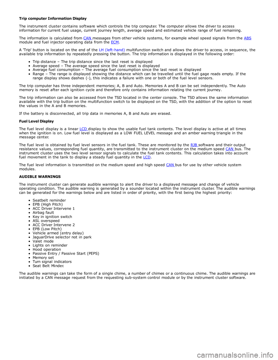
module and fuel injector operating data from the ECM.
A 'Trip' button is located on the end of the LH (left-hand) multifunction switch and allows the driver to access, in sequence, the
available trip information by repeatedly pressing the button. The trip information is displayed in the following order:
Trip distance – The trip distance since the last reset is displayed
Average speed – The average speed since the last reset is displayed
Average fuel consumption – The average fuel consumption since the last reset is displayed
Range – The range is displayed showing the distance which can be travelled until the fuel gage reads empty. If the
range display shows dashes (-), this indicates a failure with one or both of the fuel level sensors.
The trip computer has three independent memories; A, B and Auto. Memories A and B can be set independently. The Auto
memory is reset after each ignition cycle and therefore only contains information relating the current journey.
The trip information can also be accessed from the TSD located in the center console. The TSD allows the same information
available with the trip button on the multifunction switch to be displayed on the TSD, with the addition of the option to reset
the values in the A and B memories.
If the battery is disconnected, all trip data in memories A, B and Auto are erased.
Fuel Level Display
The fuel level display is a linear LCD display to show the usable fuel tank contents. The level display is active at all times when the ignition is on. Low fuel level is displayed as a LOW FUEL LEVEL message and an amber warning triangle in the
message center.
The fuel level is obtained by fuel level sensors in the fuel tank. These are monitored by the RJB software and their output resistance values, corresponding fuel quantity, are transmitted to the instrument cluster on the medium speed CAN bus. The instrument cluster uses the two level sensor signals to calculate the fuel tank contents. This calculation takes into account
fuel movement in the tank to display a steady fuel quantity in the LCD.
The fuel level information is transmitted on the medium speed and high speed CAN bus for use by other vehicle system modules.
AUDIBLE WARNINGS
The instrument cluster can generate audible warnings to alert the driver to a displayed message and change of vehicle
operating condition. The audible warning is generated by a sounder located within the instrument cluster. The audible warnings
can be generated for the warnings below and are listed in order of priority, with the first being the highest priority:
Seatbelt reminder
EPB (High Pitch)
ACC Driver Intervene 1
Airbag fault
Key in ignition switch
ASL overspeed
ACC Driver Intervene 2
EPB (Low Pitch)
Vehicle armed (entry delay)
JaguarDrive selector not in park
Valet mode
Lights on reminder
Hood operation
Passive Entry / Passive Start (PEPS)
Memory set
Turn signal indicators
Seat Belt Minder.
The audible warnings can take the form of a single chime, a number of chimes or a continuous chime. The audible warnings are
initiated by a CAN message request from the requesting sub-system control module or by the instrument cluster software.
Page 1869 of 3039
5. EQUIPMENT
All equipment used must be functionally capable of meeting the compliance requirements. Please refer to the approved
equipment document (JLR 000015).
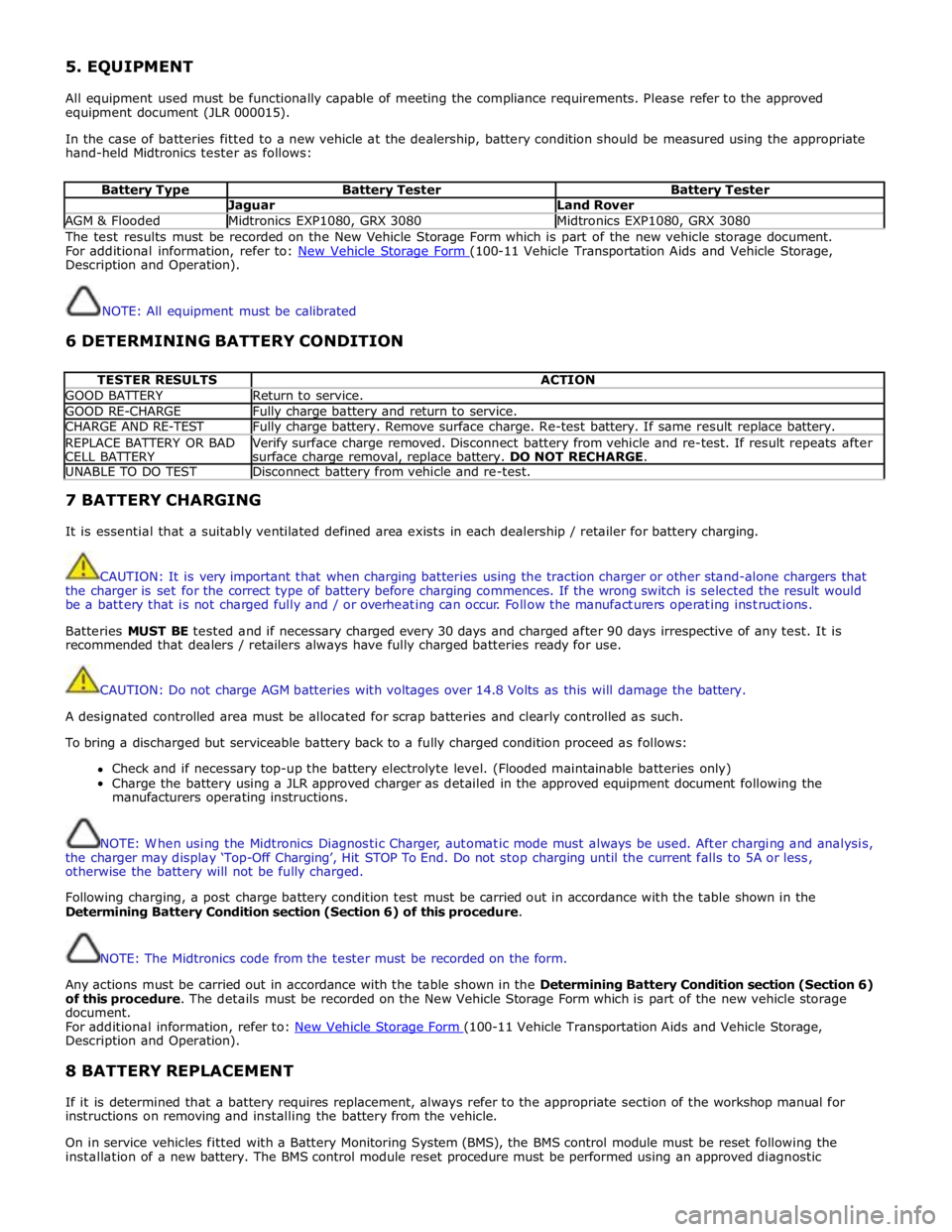
In the case of batteries fitted to a new vehicle at the dealership, battery condition should be measured using the appropriate
hand-held Midtronics tester as follows:
Battery Type Battery Tester Battery Tester Jaguar Land Rover AGM & Flooded Midtronics EXP1080, GRX 3080 Midtronics EXP1080, GRX 3080 The test results must be recorded on the New Vehicle Storage Form which is part of the new vehicle storage document.
For additional information, refer to: New Vehicle Storage Form (100-11 Vehicle Transportation Aids and Vehicle Storage, Description and Operation).
NOTE: All equipment must be calibrated
6 DETERMINING BATTERY CONDITION
TESTER RESULTS ACTION GOOD BATTERY Return to service. GOOD RE-CHARGE Fully charge battery and return to service. CHARGE AND RE-TEST Fully charge battery. Remove surface charge. Re-test battery. If same result replace battery. REPLACE BATTERY OR BAD
CELL BATTERY Verify surface charge removed. Disconnect battery from vehicle and re-test. If result repeats after
surface charge removal, replace battery. DO NOT RECHARGE. UNABLE TO DO TEST Disconnect battery from vehicle and re-test. 7 BATTERY CHARGING
It is essential that a suitably ventilated defined area exists in each dealership / retailer for battery charging.
CAUTION: It is very important that when charging batteries using the traction charger or other stand-alone chargers that
the charger is set for the correct type of battery before charging commences. If the wrong switch is selected the result would
be a battery that is not charged fully and / or overheating can occur. Follow the manufacturers operating instructions.
Batteries MUST BE tested and if necessary charged every 30 days and charged after 90 days irrespective of any test. It is
recommended that dealers / retailers always have fully charged batteries ready for use.
CAUTION: Do not charge AGM batteries with voltages over 14.8 Volts as this will damage the battery.
A designated controlled area must be allocated for scrap batteries and clearly controlled as such.
To bring a discharged but serviceable battery back to a fully charged condition proceed as follows:
Check and if necessary top-up the battery electrolyte level. (Flooded maintainable batteries only)
Charge the battery using a JLR approved charger as detailed in the approved equipment document following the
manufacturers operating instructions.
NOTE: When using the Midtronics Diagnostic Charger, automatic mode must always be used. After charging and analysis,
the charger may display ‘Top-Off Charging’, Hit STOP To End. Do not stop charging until the current falls to 5A or less,
otherwise the battery will not be fully charged.
Following charging, a post charge battery condition test must be carried out in accordance with the table shown in the
Determining Battery Condition section (Section 6) of this procedure.
NOTE: The Midtronics code from the tester must be recorded on the form.
Any actions must be carried out in accordance with the table shown in the Determining Battery Condition section (Section 6)
of this procedure. The details must be recorded on the New Vehicle Storage Form which is part of the new vehicle storage
document.
For additional information, refer to: New Vehicle Storage Form (100-11 Vehicle Transportation Aids and Vehicle Storage, Description and Operation).
8 BATTERY REPLACEMENT
If it is determined that a battery requires replacement, always refer to the appropriate section of the workshop manual for
instructions on removing and installing the battery from the vehicle.
On in service vehicles fitted with a Battery Monitoring System (BMS), the BMS control module must be reset following the
installation of a new battery. The BMS control module reset procedure must be performed using an approved diagnostic
Page 1871 of 3039

Published: 21-Dec-2012
Battery and Charging System - General Information - Quiescent Drain
Description and Operation
VEHICLE QUIESCENT CURRENT TESTING
On vehicles fitted with a Battery Monitoring System (BMS), the diagnostic routine for quiescent drain testing in the approved
Jaguar or Land Rover diagnostic system should be utilized.
If a customer complains of a vehicle battery that discharges continuously or when left for a prolonged period of time, it is
recommended that a quiescent drain test is performed as described below.
The battery drain should be measured using the approved Jaguar or Land Rover diagnostic system or a Digital Multi-Meter
(DVOM). A procedure for quiescent drain measurement using the diagnostic system is available in the Diagnosis and Testing
section of the Workshop Manual. The vehicle should be in the locked/armed state (for example vehicle alarm fully armed), all
doors, engine and luggage compartment lids are open and latched (so as to appear closed from an electrical point of view).
The test should take place after the vehicle has entered shutdown mode. The time taken for this to occur after the ignition is
switched off varies according to model (Refer to the Topix On line resource for details).
When the vehicle is armed, the effect of the security system Light Emitting Diode (LED) flashing is to cause a pulsation in the
measured current drain. In this case, either the average current should be taken (using a Digital Multi- Meter (DVOM) with an
averaging system) or the current reading taken, ignoring the brief high current peaks.
EQUIPMENT
Approved Jaguar or Land Rover diagnostic system with current probeOR Digital Multi-Meter (DVOM) with current probe.
METHOD OF MEASUREMENT
Using an Approved Jaguar or Land Rover Diagnostic System.
1. Switch off all electrical loads and ensure that the ignition is off
2. Connect the current probe to the approved Jaguar or Land Rover diagnostic system
3. Calibrate the probe
4. Install a clamp around the battery lead/junction box lead
5. Go to the Quiescent Current Testing section in this procedure
Using a digital multimeter
Do not use an in-line DVOM to measure the quiescent drain on vehicles fitted with an electronic throttle (for example XK 2006
onwards). The current exceeds the maximum amount the fuse in the DVOM is capable of handling.
1. Switch off all electrical loads and ensure that the ignition is off
2. Connect the current probe to the digital multmeter
3. Calibrate the probe
4. Install a clamp around the battery lead/junction box lead
5. Go to the Quiescent Current Testing section in this procedure
QUIESCENT CURRENT TESTING
1. Switch ignition to ‘on’ or select ignition mode in keyless vehicles and switch to ‘off’ (do not crank)
2. Remove key from ignition switch (if equipped)
3. Open and latch all doors, hood and luggage compartment lid
4. Lock the vehicle using the remote function on the remote handset. (Single lock only to avoid volumetric alarm arming)
5. Remove any other potential electrical drains such as accessories plugged into accessory sockets
6. Record the amperage readings after the shutdown period referenced in the Topix on line resource for details. Note all
cars from 10MY onwards and XK from 07MY and XF from 08MY should be less than 30mA after 30 minutes
7. Record the final reading on the battery report form
The preferred method of testing following an excessive current consumption figure is to use a current probe around individual
junction box leads to the various suspected circuits to identify a potential cause. This is in preference to the old method of
removing fuses for the following reasons:
The drain may be caused by a module remaining active and preventing the quiescent drain from reducing to normal
levels
The drain may be caused by a relay winding that is activated. Pulling the fuse can allow this to ‘reset’ and the drain will
be lost and go un-diagnosed
QUIESCENT DRAIN - TYPICAL VALUES
NOTE: The quiescent drain after the initial shutdown period should not exceed the value shown in the table.
Jaguar Quiescent Drain Values
MODEL SHUT DOWN PERIOD (minutes) TYPICAL VALUES BATTERY DRAIN (mA) XJS 3.2 60 <30 Sovereign 3.2 60 <37.3
Page 1878 of 3039
Battery, Mounting and Cables - Battery and Cables - Overview
Description and Operation
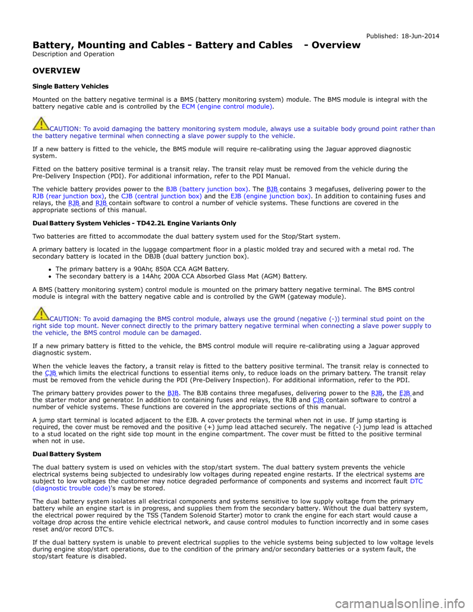
OVERVIEW
Single Battery Vehicles Published: 18-Jun-2014
Mounted on the battery negative terminal is a BMS (battery monitoring system) module. The BMS module is integral with the
battery negative cable and is controlled by the ECM (engine control module).
CAUTION: To avoid damaging the battery monitoring system module, always use a suitable body ground point rather than
the battery negative terminal when connecting a slave power supply to the vehicle.
If a new battery is fitted to the vehicle, the BMS module will require re-calibrating using the Jaguar approved diagnostic
system.
Fitted on the battery positive terminal is a transit relay. The transit relay must be removed from the vehicle during the
Pre-Delivery Inspection (PDI). For additional information, refer to the PDI Manual.
The vehicle battery provides power to the BJB (battery junction box). The BJB contains 3 megafuses, delivering power to the RJB (rear junction box), the CJB (central junction box) and the EJB (engine junction box). In addition to containing fuses and
relays, the RJB and RJB contain software to control a number of vehicle systems. These functions are covered in the appropriate sections of this manual.
Dual Battery System Vehicles - TD42.2L Engine Variants Only
Two batteries are fitted to accommodate the dual battery system used for the Stop/Start system.
A primary battery is located in the luggage compartment floor in a plastic molded tray and secured with a metal rod. The
secondary battery is located in the DBJB (dual battery junction box).
The primary battery is a 90Ahr, 850A CCA AGM Battery.
The secondary battery is a 14Ahr, 200A CCA Absorbed Glass Mat (AGM) Battery.
A BMS (battery monitoring system) control module is mounted on the primary battery negative terminal. The BMS control
module is integral with the battery negative cable and is controlled by the GWM (gateway module).
CAUTION: To avoid damaging the BMS control module, always use the ground (negative (-)) terminal stud point on the
right side top mount. Never connect directly to the primary battery negative terminal when connecting a slave power supply to
the vehicle, the BMS control module can be damaged.
If a new primary battery is fitted to the vehicle, the BMS control module will require re-calibrating using a Jaguar approved
diagnostic system.
When the vehicle leaves the factory, a transit relay is fitted to the battery positive terminal. The transit relay is connected to
the CJB which limits the electrical functions to essential items only, to reduce loads on the primary battery. The transit relay must be removed from the vehicle during the PDI (Pre-Delivery Inspection). For additional information, refer to the PDI.
The primary battery provides power to the BJB. The BJB contains three megafuses, delivering power to the RJB, the EJB and the starter motor and generator. In addition to containing fuses and relays, the RJB and CJB contain software to control a number of vehicle systems. These functions are covered in the appropriate sections of this manual.
A jump start terminal is located adjacent to the EJB. A cover protects the terminal when not in use. If jump starting is
required, the cover must be removed and the positive (+) jump lead attached securely. The negative (-) jump lead is attached
to a stud located on the right side top mount in the engine compartment. The cover must be fitted to the positive terminal
when not in use.
Dual Battery System
The dual battery system is used on vehicles with the stop/start system. The dual battery system prevents the vehicle
electrical systems being subjected to undesirably low voltages during repeated engine restarts. If the electrical systems are
subject to low voltages the customer may notice degraded performance of components and systems and incorrect fault DTC
(diagnostic trouble code)'s may be stored.
The dual battery system isolates all electrical components and systems sensitive to low supply voltage from the primary
battery while an engine start is in progress, and supplies them from the secondary battery. Without the dual battery system,
the electrical power required by the TSS (Tandem Solenoid Starter) motor to crank the engine for each start would cause a
voltage drop across the entire vehicle electrical network, and cause control modules to function incorrectly and in some cases
reset and/or record DTC's.
If the dual battery system is unable to prevent electrical supplies to the vehicle systems being subjected to low voltage levels
during engine stop/start operations, due to the condition of the primary and/or secondary batteries or a system fault, the
stop/start feature is disabled.
Page 1882 of 3039

11 Secondary battery 12 Dual Battery Junction Box (DBJB) 13 Rear Junction Box (RJB) 14 Megafuse 15 Battery Junction box (BJB) 16 Primary battery
System Operation BATTERY MONITORING SYSTEM - TD4 2.2L DIESEL VEHICLES ONLY
Periodically the battery monitoring system module will instigate a self-calibration routine. To self calibrate, the battery
monitoring system first charges the battery to its full condition.
NOTE: If the vehicle is only driven for short periods the charging process could take a number of days to complete.
Once the battery is fully charged, the battery monitoring system will discharge the battery to approximately 75% of its full
state of charge, but never lower than 12.2 V. The time taken to complete this part of the routine is dependent on the electrical
load on the vehicle.
When the second part of the routine has been successfully completed, the battery monitoring system will return the battery to
its optimum level of charge. The optimum level of charge will be between 12.6 V and 15 V, depending on battery condition,
temperature and loading.
The battery monitoring system module also monitors the battery condition with the engine switched off. If a low voltage
condition is detected the module can request the infotainment system is switched off to protect battery voltage. Once the
infotainment system has been switched off, the vehicle must be run for at least 5 minutes to charge the battery before the
infotainment system can be operated with the engine switched off.
BATTERY MONITORING SYSTEM - SINGLE AND DUAL BATTERY SYSTEM VEHICLES
When the ignition is off (power mode 0), the BMS control module records the primary battery state of charge and begins to
monitor the battery condition from this point.
If the battery state of charge falls by 7%, the BMS control module will monitor the primary battery for 5 minutes. If after the 5
minute monitoring period, the primary battery charge has continued to fall due to the quiescent drain current being too high,
the BMS control module will determine that some control modules are still 'awake'. The BMS control module sends a shutdown
message on the LIN (local interconnect network) bus to the GWM (Gateway Module). The GWM sends a CAN (controller area
network) bus message on both the medium and high speed networks to all control modules, requesting them to shutdown.
The BMS control module will monitor the primary battery state of charge for a further 5 minutes and determine if the primary
battery state of charge is still dropping. If a quiescent drain current continues, the primary battery state of charge will
continue to drop. If the state of charge falls to 12% of the initial monitoring value, the BMS control module determines that
one or more control modules are still awake and a failure to respond to the shutdown request may indicate an error state
within the control module(s).
BMS Low Battery Warning and Energy Management Messages
The BMS continuously monitors the condition of the primary vehicle battery. If excessive battery discharge occurs, the system
will begin to shut down non-essential electrical systems in order to protect the battery.
If the BMS calculates that battery condition is not within set parameters, there are 3 messages that can be displayed, 2 on the
touch screen and 1 on the message center. These inform the user that the battery is either at a low level of charge or the
engine-off power consumption limit has been exceeded.
Low Battery - Please switch engine on or system will shutdown in 3 minutes: is displayed as a Warning on the
touch screen if the engine is not running. This indicates that the battery has fallen below a predefined threshold. As
soon as the battery is charged back above this threshold then the message will be removed.
Low Battery - Please start your engine is displayed on the message center if the engine is not running. This indicates
that the battery has fallen below a predefined threshold. As soon as the battery is charged back above this threshold
then the message will be removed or it can be manually removed by pressing 'OK'.
System will shut down in 3 minutes: is displayed as an Energy management on the touch screen if the engine is not
running, and system features are causing excessive battery discharge. After 3 minutes the BMS will begin shutting
down vehicle systems. Normal system operation will resume when the engine is started.
This is based on a percentage of battery capacity available for the customer to use with the engine off. The percentage can
change based upon several factors.
Once triggered, the resetting of this message will not occur until the vehicle is driven for 10 minutes with the engine running
(to allow the battery to recoup any lost charge). However, if the engine is run for less than 10 minutes, the message will only
be displayed after an additional 5 minutes with the ignition on but engine off.
BMS Control Module Self Calibration
Periodically the BMS control module will instigate a self-calibration routine. To self calibrate, the battery monitoring system www.JagDocs.com
Page 1900 of 3039
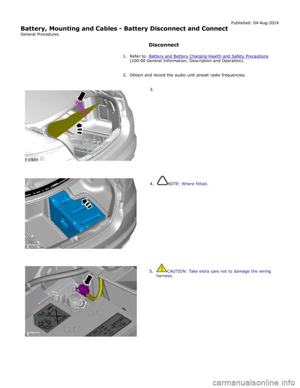
(100-00 General Information, Description and Operation).
2. Obtain and record the audio unit preset radio frequencies.
3.
4. NOTE: Where fitted.
5. CAUTION: Take extra care not to damage the wiring
harness.
Page 1903 of 3039
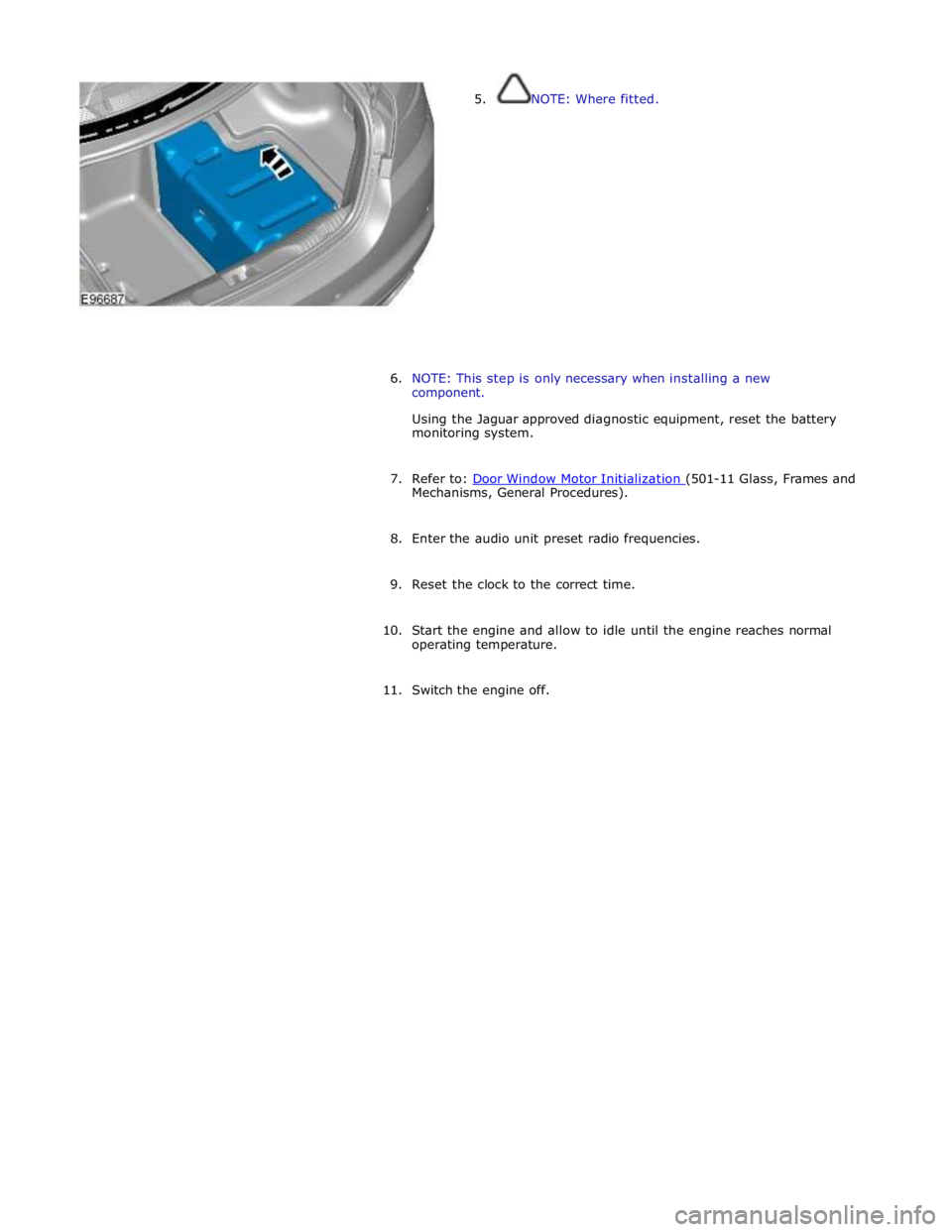
5. NOTE: Where fitted.
6. NOTE: This step is only necessary when installing a new
component.
Using the Jaguar approved diagnostic equipment, reset the battery
monitoring system.
7. Refer to: Door Window Motor Initialization (501-11 Glass, Frames and Mechanisms, General Procedures).
8. Enter the audio unit preset radio frequencies.
9. Reset the clock to the correct time.
10. Start the engine and allow to idle until the engine reaches normal
operating temperature.
11. Switch the engine off.
Page 1904 of 3039
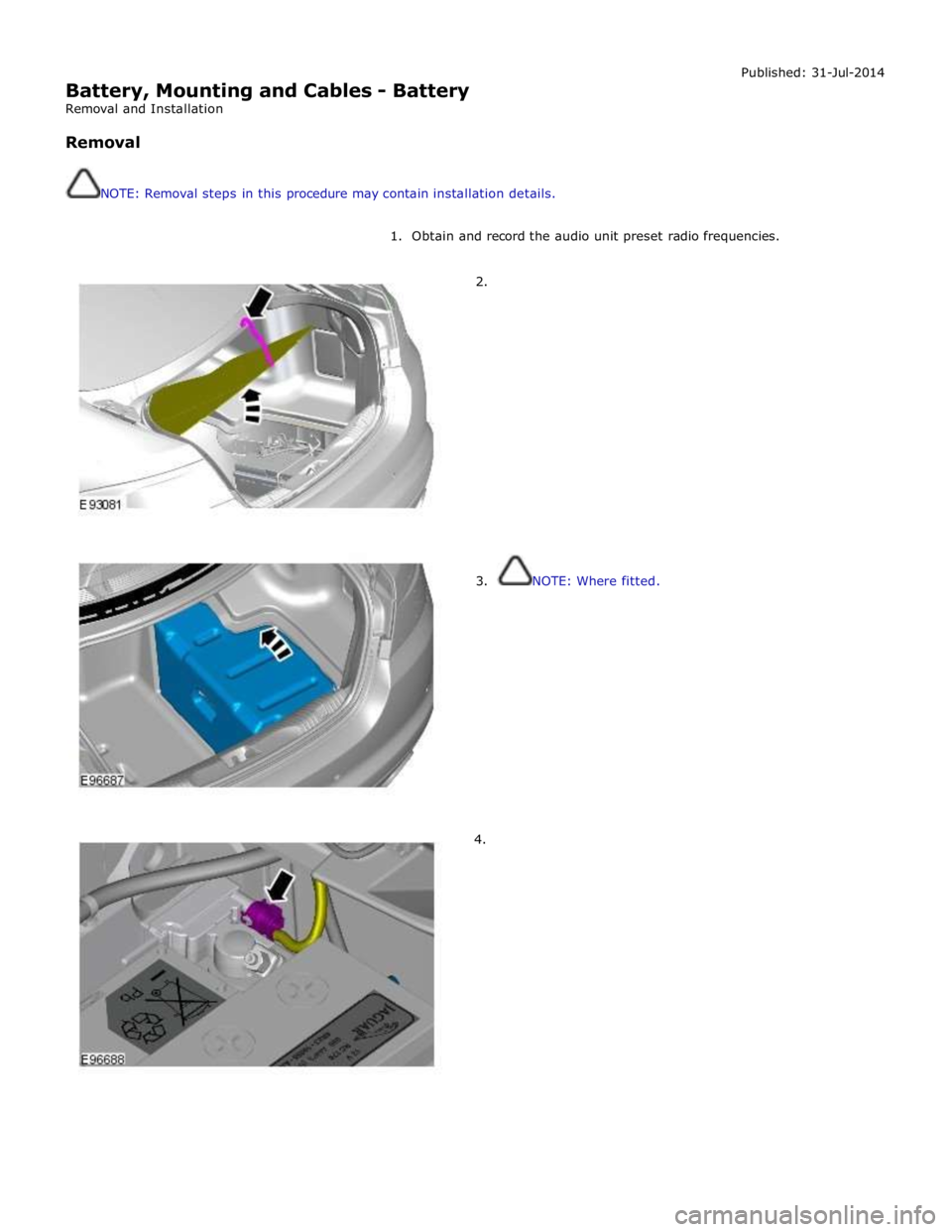
Battery, Mounting and Cables - Battery
Removal and Installation
Removal
NOTE: Removal steps in this procedure may contain installation details. Published: 31-Jul-2014
1. Obtain and record the audio unit preset radio frequencies.
2.
3. NOTE: Where fitted.
4.
Page 1907 of 3039
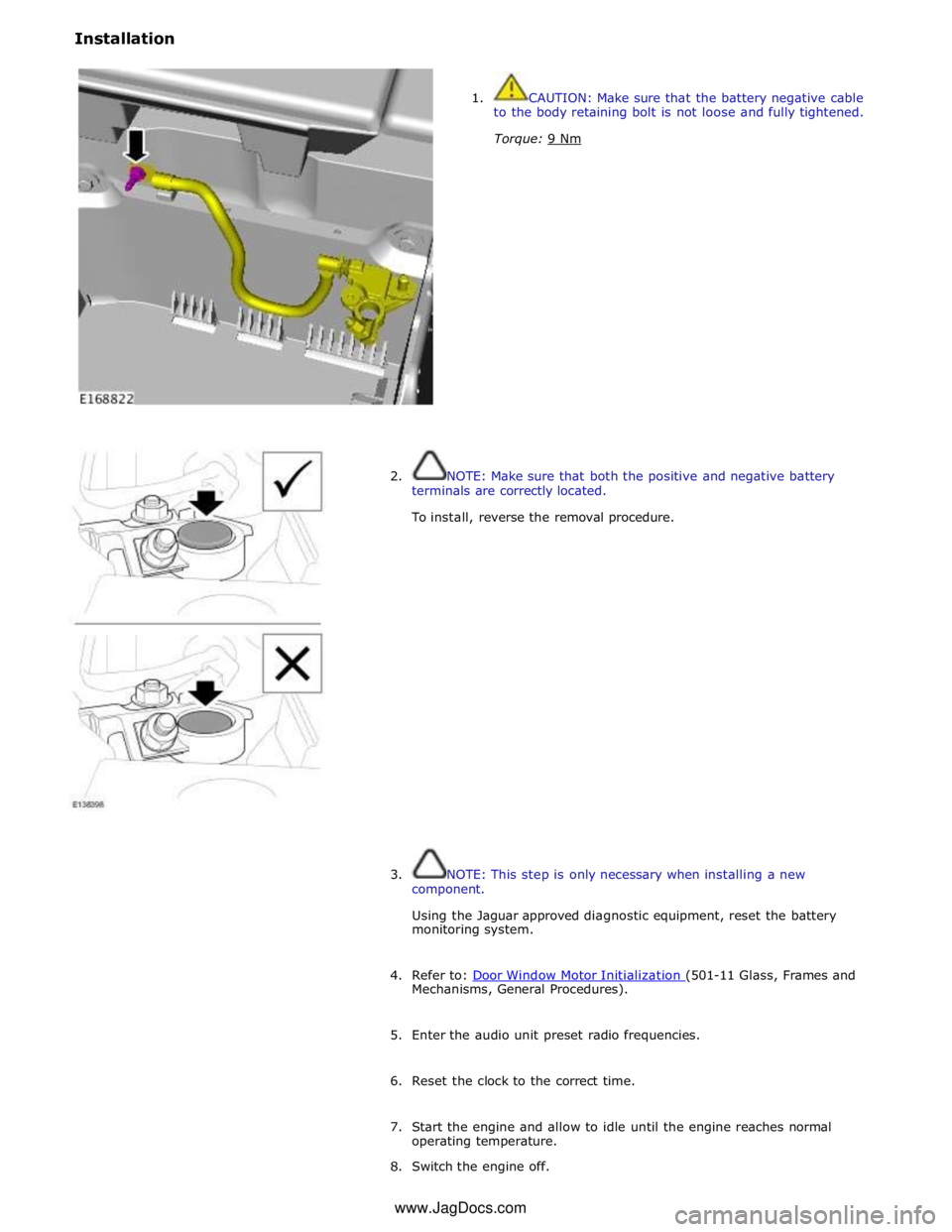
Installation
1. CAUTION: Make sure that the battery negative cable
to the body retaining bolt is not loose and fully tightened.
Torque: 9 Nm
2. NOTE: Make sure that both the positive and negative battery
terminals are correctly located.
To install, reverse the removal procedure.
3. NOTE: This step is only necessary when installing a new
component.
Using the Jaguar approved diagnostic equipment, reset the battery
monitoring system.
4. Refer to: Door Window Motor Initialization (501-11 Glass, Frames and Mechanisms, General Procedures).
5. Enter the audio unit preset radio frequencies.
6. Reset the clock to the correct time.
7. Start the engine and allow to idle until the engine reaches normal
operating temperature.
8. Switch the engine off. www.JagDocs.com