reset JAGUAR XFR 2010 1.G Owner's Guide
[x] Cancel search | Manufacturer: JAGUAR, Model Year: 2010, Model line: XFR, Model: JAGUAR XFR 2010 1.GPages: 3039, PDF Size: 58.49 MB
Page 2010 of 3039

Published: 23-Jan-2012
Information and Entertainment System - DTC: Audio Input Control Module - Audio Input Control Module
Diagnosis and Testing
Principle of Operation
This section of the manual concerns diagnostic procedures for the Dension audio input control module. For a detailed
description of the information and entertainment system, refer to the relevant description and operation sections in the
workshop manual
Inspection and Verification
CAUTION: Diagnosis by substitution from a donor vehicle is NOT acceptable. Substitution of control modules does not
guarantee confirmation of a fault, and may also cause additional faults in the vehicle being tested and/or the donor vehicle
1. Verify the customer concern
2. Visually inspect for obvious signs of damage and system integrity
Visual Inspection
Mechanical Electrical
Audio input control module
Audio amplifier module
Integrated audio module
Integrated control panel
Touch screen display
Loudspeakers
Fuses
Loose or corroded connector(s)
Audio amplifier module
Integrated audio module
Integrated control panel
Touch screen display
Loudspeakers
3. If an obvious cause for an observed or reported concern is found, correct the cause (if possible) before proceeding to
the next step
4. If the cause is not visually evident, check for diagnostic trouble codes and refer to the relevant diagnostic trouble codes
index
Audio Input Control Module Diagnostics
NOTE: If problems are reported with the audio input control module, prior to further diagnostic checks or replacement of
components, first perform a hardware reset by depressing the reset button for a minimum of two seconds. If problems persist,
refer to the symptom charts below
Performing A Hardware Reset
Symptom Chart - Intermittent Fault With iPOD® Playback
Symptom Possible Cause Action Intermittent fault
with iPOD®
playback
The connected iPOD® unit has
crashed or frozen
See diagnostic procedures as specified in pinpoint test A1
"Check The Operation Of The iPOD®" below GO to
Pinpoint Test A. www.JagDocs.com
Page 2013 of 3039
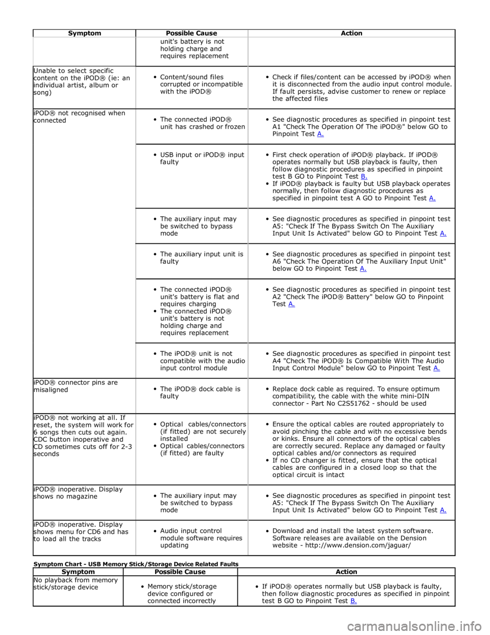
Symptom Possible Cause Action unit's battery is not
holding charge and
requires replacement Unable to select specific
content on the iPOD® (ie: an
individual artist, album or
song)
Content/sound files
corrupted or incompatible
with the iPOD®
Check if files/content can be accessed by iPOD® when
it is disconnected from the audio input control module.
If fault persists, advise customer to renew or replace
the affected files iPOD® not recognised when
connected
The connected iPOD®
unit has crashed or frozen
See diagnostic procedures as specified in pinpoint test
A1 "Check The Operation Of The iPOD®" below GO to
Pinpoint Test A.
USB input or iPOD® input
faulty
First check operation of iPOD® playback. If iPOD®
operates normally but USB playback is faulty, then
follow diagnostic procedures as specified in pinpoint
test B GO to Pinpoint Test B. If iPOD® playback is faulty but USB playback operates
normally, then follow diagnostic procedures as
specified in pinpoint test A GO to Pinpoint Test A.
The auxiliary input may
be switched to bypass
mode
See diagnostic procedures as specified in pinpoint test
A5: "Check If The Bypass Switch On The Auxiliary
Input Unit Is Activated" below GO to Pinpoint Test A.
The auxiliary input unit is
faulty
See diagnostic procedures as specified in pinpoint test
A6 "Check The Operation Of The Auxiliary Input Unit"
below GO to Pinpoint Test A.
The connected iPOD®
unit's battery is flat and
requires charging
The connected iPOD®
unit's battery is not
holding charge and
requires replacement
See diagnostic procedures as specified in pinpoint test
A2 "Check The iPOD® Battery" below GO to Pinpoint
Test A.
The iPOD® unit is not
compatible with the audio
input control module
See diagnostic procedures as specified in pinpoint test
A4 "Check The iPOD® Is Compatible With The Audio
Input Control Module" below GO to Pinpoint Test A. iPOD® connector pins are
misaligned
The iPOD® dock cable is
faulty
Replace dock cable as required. To ensure optimum
compatibility, the cable with the white mini-DIN
connector - Part No C2S51762 - should be used iPOD® not working at all. If
reset, the system will work for
6 songs then cuts out again.
CDC button inoperative and
CD sometimes cuts off for 2-3
seconds
Optical cables/connectors
(if fitted) are not securely
installed
Optical cables/connectors
(if fitted) are faulty
Ensure the optical cables are routed appropriately to
avoid pinching the cable and with no excessive bends
or kinks. Ensure all connectors of the optical cables
are correctly secured. Replace any damaged or faulty
optical cables and/or connectors as required
If no CD changer is fitted, ensure that the optical
cables are configured in a closed loop so that the
optical circuit is intact iPOD® inoperative. Display
shows no magazine
The auxiliary input may
be switched to bypass
mode
See diagnostic procedures as specified in pinpoint test
A5: "Check If The Bypass Switch On The Auxiliary
Input Unit Is Activated" below GO to Pinpoint Test A. iPOD® inoperative. Display
shows menu for CD6 and has
to load all the tracks
Audio input control
module software requires
updating
Download and install the latest system software.
Software releases are available on the Dension
website - http://www.dension.com/jaguar/ Symptom Chart - USB Memory Stick/Storage Device Related Faults
Symptom Possible Cause Action No playback from memory
stick/storage device
Memory stick/storage
device configured or
connected incorrectly
If iPOD® operates normally but USB playback is faulty,
then follow diagnostic procedures as specified in pinpoint
test B GO to Pinpoint Test B.
Page 2015 of 3039
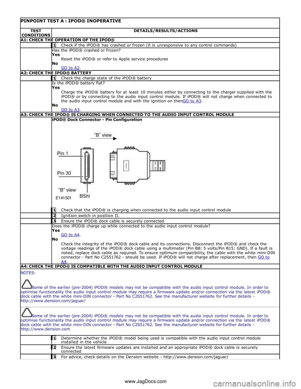
PINPOINT TEST A : IPOD® INOPERATIVE TEST
CONDITIONS DETAILS/RESULTS/ACTIONS A1: CHECK THE OPERATION OF THE IPOD® 1 Check if the iPOD® has crashed or frozen (it is unresponsive to any control commands) Has the iPOD® crashed or frozen?
Yes
Reset the iPOD® or refer to Apple service procedures
No
GO to A2. A2: CHECK THE IPOD® BATTERY 1 Check the charge state of the iPOD® battery Is the iPOD® battery flat?
Yes
Charge the iPOD® battery for at least 10 minutes either by connecting to the charger supplied with the
iPOD® or by connecting to the audio input control module. If iPOD® will not charge when connected to
the audio input control module and with the ignition on thenGO to A3. No
GO to A3. A3: CHECK THE IPOD® IS CHARGING WHEN CONNECTED TO THE AUDIO INPUT CONTROL MODULE iPOD® Dock Connector - Pin Configuration
1 Check that the iPOD® is charging when connected to the audio input control module 2 Ignition switch in position II. 3 Ensure the iPOD® dock cable is securely connected Does the iPOD® charge up while connected to the audio input control module?
Yes
GO to A4. No
Check the integrity of the iPOD® dock cable and its connections. Disconnect the iPOD® and check the
voltage readings of the iPOD® dock cable using a multimeter (Pin B8: 5 volts/Pin B15: GND). If a fault is
noted, replace dock cable as required. To ensure optimum compatibility, the cable with the white mini-DIN
connector - Part No C2S51762 - should be used. If iPOD® will not charge after replacement, then GO to A4. A4: CHECK THE IPOD® IS COMPATIBLE WITH THE AUDIO INPUT CONTROL MODULE NOTES:
Some of the earlier (pre-2004) iPOD® models may not be compatible with the audio input control module. In order to
optimise functionality the audio input control module may require a firmware update and/or connection via the latest iPOD®
dock cable with the white mini-DIN connector - Part No C2S51762. See the manufacturer website for further details -
http://www.dension.com/jaguar/
Some of the earlier (pre-2004) iPOD® models may not be compatible with the audio input control module. In order to
optimise functionality the audio input control module may require a firmware update and/or connection via the latest iPOD®
dock cable with the white mini-DIN connector - Part No C2S51762. See the manufacturer website for further details -
http://www.dension.com 1 Determine whether the iPOD® model being used is compatible with the audio input control module installed in the vehicle 2 Ensure the latest firmware updates are installed and an appropriate iPOD® dock cable is securely connected 3 For advice, check details on the Dension website - http://www.dension.com/jaguar/ www.JagDocs.com
Page 2027 of 3039
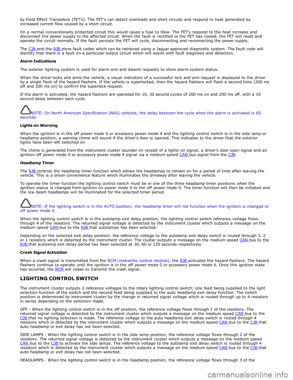
by Field Effect Transistors (FET's). The FET's can detect overloads and short circuits and respond to heat generated by
increased current flow caused by a short circuit.
On a normal conventionally protected circuit this would cause a fuse to blow. The FET's respond to the heat increase and
disconnect the power supply to the affected circuit. When the fault is rectified or the FET has cooled, the FET will reset and
operate the circuit normally. If the fault persists the FET will cycle, disconnecting and reconnecting the power supply.
The CJB and the RJB store fault codes which can be retrieved using a Jaguar approved diagnostic system. The fault code will identify that there is a fault on a particular output circuit which will assist with fault diagnosis and detection.
Alarm Indications
The exterior lighting system is used for alarm arm and disarm requests to show alarm system status.
When the driver locks and arms the vehicle, a visual indication of a successful lock and arm request is displayed to the driver
by a single flash of the hazard flashers. If the vehicle is superlocked, then the hazard flashers will flash a second time (200 ms
off and 200 ms on) to confirm the superlock request.
If the alarm is activated, the hazard flashers are operated for 10, 30 second cycles of 200 ms on and 200 ms off, with a 10
second delay between each cycle.
NOTE: On North American Specification (NAS) vehicles, the delay between the cycle when the alarm is activated is 60
seconds.
Lights on Warning
When the ignition is in the off power mode 0 or accessory power mode 4 and the lighting control switch is in the side lamp or
headlamp position, a warning chime will sound if the driver's door is opened. This indicates to the driver that the exterior
lights have been left switched on.
The chime is generated from the instrument cluster sounder on receipt of a lights on signal, a driver's door open signal and an
ignition off power mode 0 or accessory power mode 4 signal via a medium speed CAN bus signal from the CJB. Headlamp Timer
The RJB controls the headlamp timer function which allows the headlamps to remain on for a period of time after leaving the vehicle. This is a driver convenience feature which illuminates the driveway after leaving the vehicle.
To operate the timer function the lighting control switch must be in one of the three headlamp timer positions when the
ignition status is changed from ignition on power mode 6 to the off power mode 0. The timer function will then be initiated and
the low beam headlamps will be illuminated for the selected timer period.
NOTE: If the lighting switch is in the AUTO position, the headlamp timer will not function when the ignition is changed to
off power mode 0.
When the lighting control switch is in the autolamp exit delay position, the lighting control switch reference voltage flows
through 4 of the resistors. The returned signal voltage is detected by the instrument cluster which outputs a message on the
medium speed CAN bus to the RJB that autolamps has been selected.
Depending on the selected exit delay position, the reference voltage to the autolamp exit delay switch is routed through 3, 2
or 1 resistors which is detected by the instrument cluster. The cluster outputs a message on the medium speed CAN bus to the RJB that autolamp exit delay period has been selected at 30, 60 or 120 seconds respectively. Crash Signal Activation
When a crash signal is transmitted from the RCM (restraints control module), the RJB activates the hazard flashers. The hazard flashers continue to operate until the ignition is in the off power mode 0 or accessory power mode 6. Once this ignition state
has occurred, the RCM will cease to transmit the crash signal.
LIGHTING CONTROL SWITCH
The instrument cluster outputs 2 reference voltages to the rotary lighting control switch; one feed being supplied to the light
selection function of the switch and the second feed being supplied to the auto headlamp exit delay function. The switch
position is determined by instrument cluster by the change in returned signal voltage which is routed through up to 4 resistors
in series depending on the selection made.
OFF - When the lighting control switch is in the off position, the reference voltage flows through 1 of the resistors. The
returned signal voltage is detected by the instrument cluster which outputs a message on the medium speed CAN bus to the CJB that no lighting selection is made. The reference voltage to the auto headlamp exit delay switch is routed through 4 resistors which is detected by the instrument cluster which outputs a message on the medium speed CAN bus to the CJB that auto headlamp or exit delay has not been selected.
SIDE LAMPS - When the lighting control switch is in the side lamp position, the reference voltage flows through 2 of the
resistors. The returned signal voltage is detected by the instrument cluster which outputs a message on the medium speed
CAN bus to the CJB to activate the side lamps. The reference voltage to the autolamp exit delay switch is routed through 4 resistors which is detected by the instrument cluster which outputs a message on the medium speed CAN bus to the CJB that auto headlamp or exit delay has not been selected.
HEADLAMPS - When the lighting control switch is in the headlamp position, the reference voltage flows through 3 of the
Page 2415 of 3039
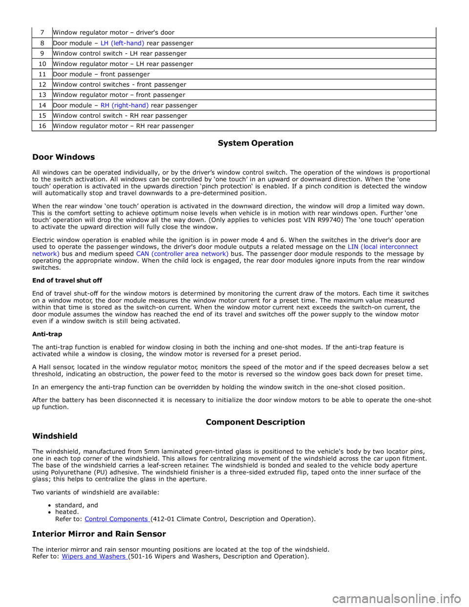
7 Window regulator motor – driver's door 8 Door module – LH (left-hand) rear passenger 9 Window control switch - LH rear passenger 10 Window regulator motor – LH rear passenger 11 Door module – front passenger 12 Window control switches - front passenger 13 Window regulator motor – front passenger 14 Door module – RH (right-hand) rear passenger 15 Window control switch - RH rear passenger 16 Window regulator motor – RH rear passenger
Door Windows System Operation
All windows can be operated individually, or by the driver’s window control switch. The operation of the windows is proportional
to the switch activation. All windows can be controlled by ‘one touch’ in an upward or downward direction. When the ‘one
touch’ operation is activated in the upwards direction ‘pinch protection‘ is enabled. If a pinch condition is detected the window
will automatically stop and travel downwards to a pre-determined position.
When the rear window ‘one touch’ operation is activated in the downward direction, the window will drop a limited way down.
This is the comfort setting to achieve optimum noise levels when vehicle is in motion with rear windows open. Further ‘one
touch’ operation will drop the window all the way down. (Only applies to vehicles post VIN R99740) The ‘one touch’ operation
to activate the upward direction will fully close the window.
Electric window operation is enabled while the ignition is in power mode 4 and 6. When the switches in the driver's door are
used to operate the passenger windows, the driver's door module outputs a related message on the LIN (local interconnect
network) bus and medium speed CAN (controller area network) bus. The passenger door module responds to the message by
operating the appropriate window. When the child lock is engaged, the rear door modules ignore inputs from the rear window
switches.
End of travel shut off
End of travel shut-off for the window motors is determined by monitoring the current draw of the motors. Each time it switches
on a window motor, the door module measures the window motor current for a preset time. The maximum value measured
within that time is stored as the switch-on current. When the window motor current next exceeds the switch-on current, the
door module assumes the window has reached the end of its travel and switches off the power supply to the window motor
even if a window switch is still being activated.
Anti-trap
The anti-trap function is enabled for window closing in both the inching and one-shot modes. If the anti-trap feature is
activated while a window is closing, the window motor is reversed for a preset period.
A Hall sensor, located in the window regulator motor, monitors the speed of the motor and if the speed decreases below a set
threshold, indicating an obstruction, the power feed to the motor is reversed so the window goes back down for preset time.
In an emergency the anti-trap function can be overridden by holding the window switch in the one-shot closed position.
After the battery has been disconnected it is necessary to initialize the door window motors to be able to operate the one-shot
up function.
Windshield Component Description
The windshield, manufactured from 5mm laminated green-tinted glass is positioned to the vehicle's body by two locator pins,
one in each top corner of the windshield. This allows for centralizing movement of the windshield across the car upon fitment.
The base of the windshield carries a leaf-screen retainer. The windshield is bonded and sealed to the vehicle body aperture
using Polyurethane (PU) adhesive. The windshield finisher is a three-sided extruded flip, taped onto the inner surface of the
glass; this helps to centralize the glass in the aperture.
Two variants of windshield are available:
standard, and
heated.
Refer to: Control Components (412-01 Climate Control, Description and Operation).
Interior Mirror and Rain Sensor
The interior mirror and rain sensor mounting positions are located at the top of the windshield.
Refer to: Wipers and Washers (501-16 Wipers and Washers, Description and Operation).
Page 2416 of 3039

Rear Window
The rear window, manufactured from toughened 4mm green-tinted glass, is positioned to the vehicle's body by two locator
pins, one in each top corner of the windshield. This allows for the centralizing movement of the windshield across the car upon
fitment. The window is bonded and sealed to the vehicle body aperture using PU adhesive. The window finisher is a
three-sided extruded flip, taped onto the inner surface of the glass; this helps to centralize the glass in the aperture.
The heated rear window grid wire and antennas are incorporated in the rear window. There are two derivatives of rear window
dependant on the TV antenna specification.
Refer to: Video System (415-01, Description and Operation).
Door Windows
The door windows are manufactured from 4.85mm green-tinted toughened glass. The driver and passenger windows are
electrically operated, and are raised and lowered by a cable mechanism; the rear glass sections in the rear doors are fixed
units.
All windows can be operated individually, or by the driver's window control switch. The operation of the windows is proportional
to the switch activation. The driver window can be controlled by 'one touch' in an upward or downward direction. When the 'one
touch' operation is activated in the upwards direction an anti-trap sensor is automatically checked prior to the window closing.
If the anti-trap sensor is inoperative the window will not close. When the anti-trap sensor detects an obstacle in the window's
path, the upward travel of the window will automatically cease. Downward travel of the window will begin and then stop when a
preset time has elapsed.
Page 2418 of 3039
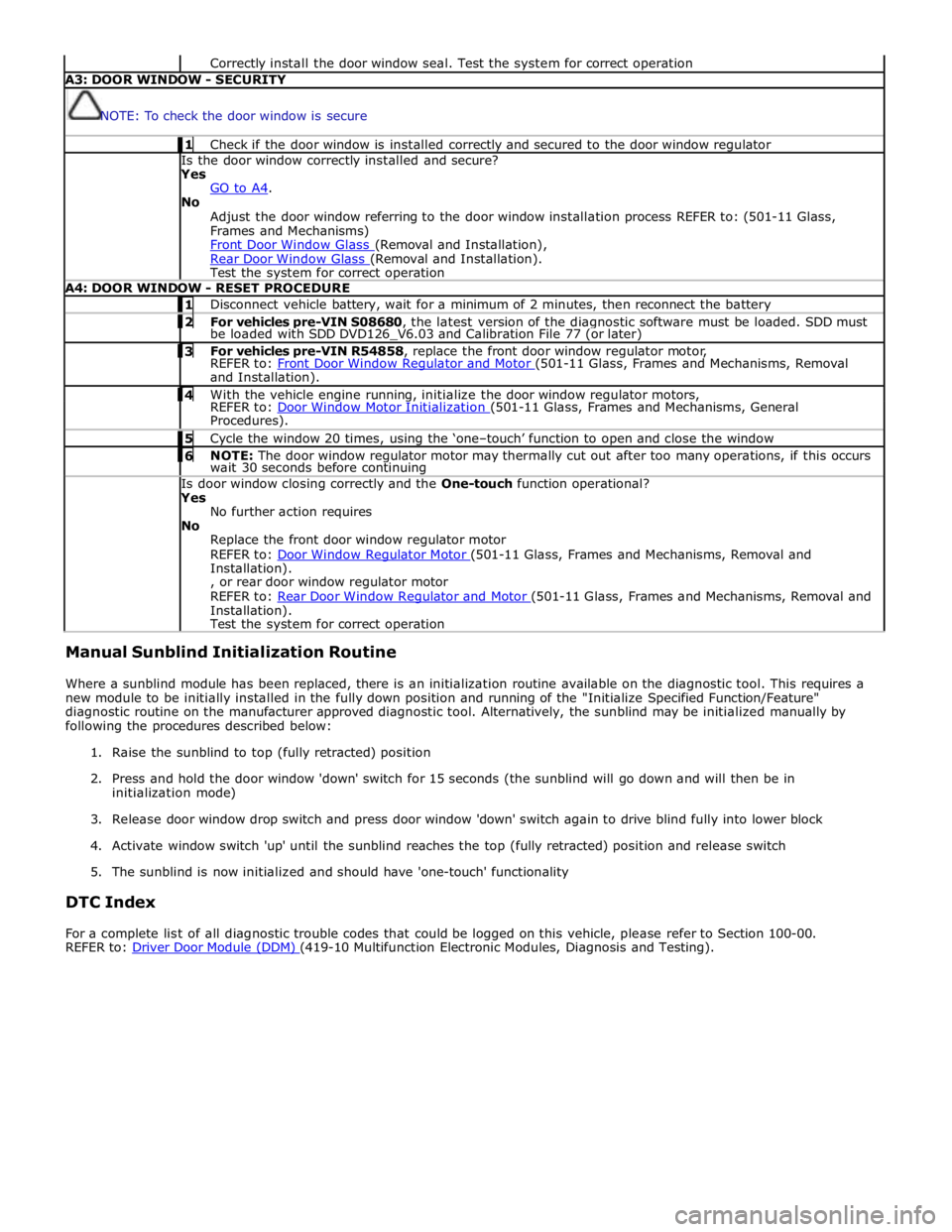
Correctly install the door window seal. Test the system for correct operation A3: DOOR WINDOW - SECURITY
NOTE: To check the door window is secure 1 Check if the door window is installed correctly and secured to the door window regulator Is the door window correctly installed and secure?
Yes
GO to A4. No
Adjust the door window referring to the door window installation process REFER to: (501-11 Glass,
Frames and Mechanisms)
Front Door Window Glass (Removal and Installation), Rear Door Window Glass (Removal and Installation). Test the system for correct operation A4: DOOR WINDOW - RESET PROCEDURE 1 Disconnect vehicle battery, wait for a minimum of 2 minutes, then reconnect the battery 2 For vehicles pre-VIN S08680, the latest version of the diagnostic software must be loaded. SDD must be loaded with SDD DVD126_V6.03 and Calibration File 77 (or later) 3 For vehicles pre-VIN R54858, replace the front door window regulator motor, REFER to: Front Door Window Regulator and Motor (501-11 Glass, Frames and Mechanisms, Removal and Installation). 4 With the vehicle engine running, initialize the door window regulator motors, REFER to: Door Window Motor Initialization (501-11 Glass, Frames and Mechanisms, General Procedures). 5 Cycle the window 20 times, using the ‘one–touch’ function to open and close the window 6 NOTE: The door window regulator motor may thermally cut out after too many operations, if this occurs wait 30 seconds before continuing Is door window closing correctly and the One-touch function operational?
Yes
No further action requires
No
Replace the front door window regulator motor
REFER to: Door Window Regulator Motor (501-11 Glass, Frames and Mechanisms, Removal and Installation).
, or rear door window regulator motor
REFER to: Rear Door Window Regulator and Motor (501-11 Glass, Frames and Mechanisms, Removal and Installation).
Test the system for correct operation Manual Sunblind Initialization Routine
Where a sunblind module has been replaced, there is an initialization routine available on the diagnostic tool. This requires a
new module to be initially installed in the fully down position and running of the "Initialize Specified Function/Feature"
diagnostic routine on the manufacturer approved diagnostic tool. Alternatively, the sunblind may be initialized manually by
following the procedures described below:
1. Raise the sunblind to top (fully retracted) position
2. Press and hold the door window 'down' switch for 15 seconds (the sunblind will go down and will then be in
initialization mode)
3. Release door window drop switch and press door window 'down' switch again to drive blind fully into lower block
4. Activate window switch 'up' until the sunblind reaches the top (fully retracted) position and release switch
5. The sunblind is now initialized and should have 'one-touch' functionality
DTC Index
For a complete list of all diagnostic trouble codes that could be logged on this vehicle, please refer to Section 100-00.
REFER to: Driver Door Module (DDM) (419-10 Multifunction Electronic Modules, Diagnosis and Testing).
Page 2538 of 3039
HEADLAMP POWERWASHERS
The headlamp powerwash is activated when the driver requests windshield washer operation. The CJB receives the driver request via a CAN bus message from the instrument cluster. The CJB then checks for an exterior lights active signal and that a low washer fluid level signal is not present.
The CJB outputs a control voltage to a headlamp powerwash pump relay located in the EJB. The relay is energized by the CJB for a pre-determined period to allow the headlamp telescopic washers to operate.
The CJB monitors the driver washer requests and only operates the headlamp powerwash on every fourth request for windshield washer operation, provided that 10 minutes have elapsed since the last headlamp powerwash operation. The
powerwash sequence is reset when the headlamps or the ignition is switched off.
NOTE: If a low fluid reservoir level is present the CJB prohibits headlamp powerwash.
RAIN/LIGHT SENSOR
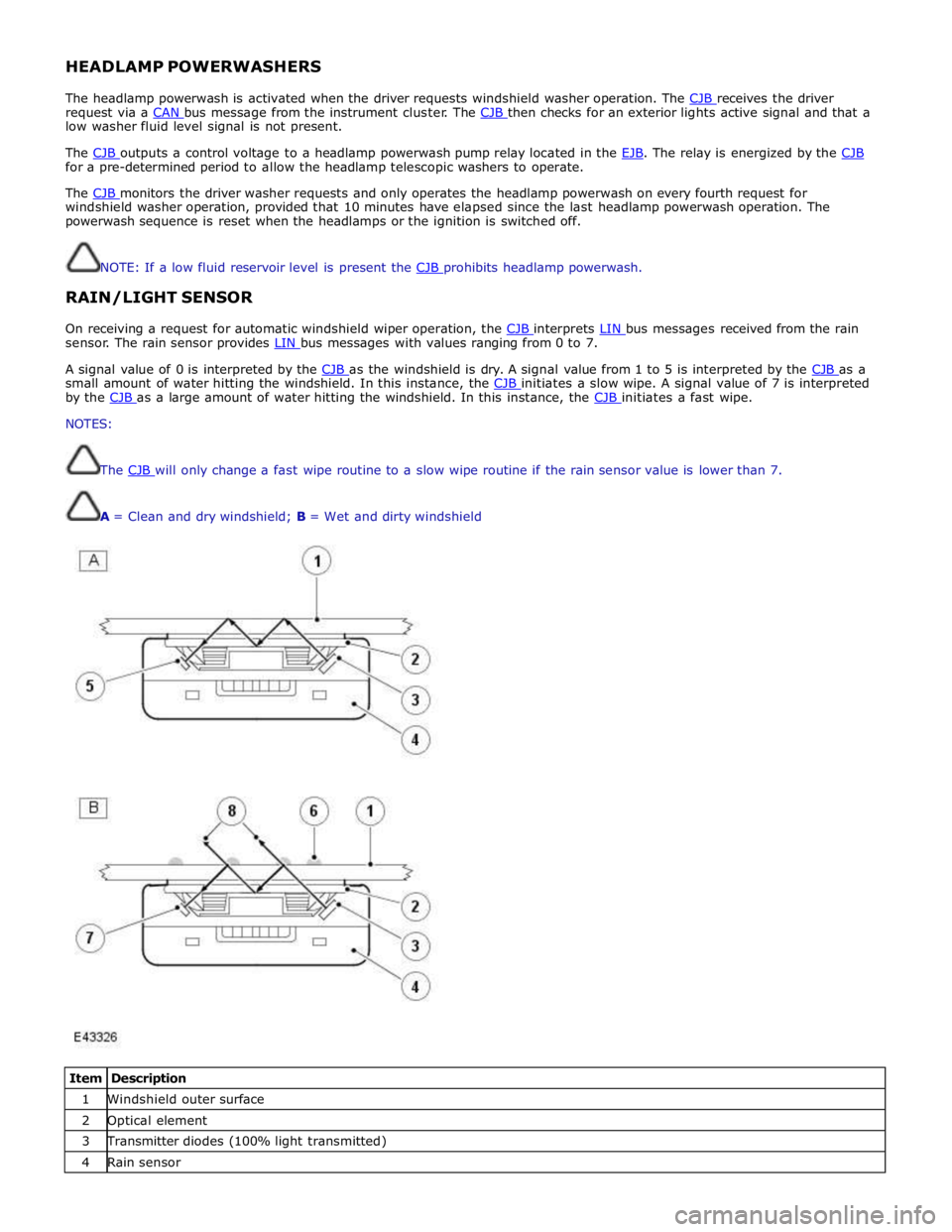
On receiving a request for automatic windshield wiper operation, the CJB interprets LIN bus messages received from the rain sensor. The rain sensor provides LIN bus messages with values ranging from 0 to 7.
A signal value of 0 is interpreted by the CJB as the windshield is dry. A signal value from 1 to 5 is interpreted by the CJB as a small amount of water hitting the windshield. In this instance, the CJB initiates a slow wipe. A signal value of 7 is interpreted by the CJB as a large amount of water hitting the windshield. In this instance, the CJB initiates a fast wipe. NOTES:
The CJB will only change a fast wipe routine to a slow wipe routine if the rain sensor value is lower than 7.
A = Clean and dry windshield; B = Wet and dirty windshield
Item Description 1 Windshield outer surface 2 Optical element 3 Transmitter diodes (100% light transmitted) 4 Rain sensor