torque JAGUAR XFR 2010 1.G Owner's Guide
[x] Cancel search | Manufacturer: JAGUAR, Model Year: 2010, Model line: XFR, Model: JAGUAR XFR 2010 1.GPages: 3039, PDF Size: 58.49 MB
Page 439 of 3039
Wheels and Tires - Wheels and Tires - Overview
Description and Operation
OVERVIEW Published: 25-May-2012
A number of alloy wheel designs are available ranging from 17 to 20 inch in diameter. A Tire Pressure Monitoring System
(TPMS) is used to monitor the air pressure in each tire and inform the driver if the pressure falls below predetermined
thresholds.
All wheels are of cast construction in aluminum alloy with the choice of wheel design dependant on the vehicle trim level and
engine derivative.
On normally aspirated petrol models and all diesel models a 4J X 18 inch temporary spare wheel is supplied as standard,
supercharged petrol models are supplied with a 4Jx19 inch temporary spare wheel. In some major European markets an Instant
Mobility System is offered as an alternative to the spare wheel. The Instant Mobility System is capable of providing a
temporary repair and tire inflation to a puncture of up to 6mm in diameter in the tread area of the tire. A puncture in the tire
wall cannot be repaired using the system.
The vehicle jack and accessories are stored in the spare wheel-well in the luggage compartment.
Tire Changing
WARNINGS:
Tires must be inflated to the recommended pressures when the tires are cold (ambient temperature) only. Refer to label
on the 'B' pillar for recommended tire pressures. If the tires have been subjected to use or exposed to direct sunlight, move
the vehicle into a shaded position and allow the tires to cool before checking or adjusting the pressures.
Valve stem seal, washer nut, valve core and cap should be replaced at every tire change. Valve stem seal, washer and
nut must be replaced if the valve retention nut is loosened. Sensor units and nuts must be fitted using correct torque figures
and associated profile. Damage to the vehicle and consequently injury to the vehicle's occupants may result if these
instructions are not adhered to.
NOTE: The TPMS valve should be serviced using the suitable service kit, each time the tyre is dismounted, to ensure an
air tight seal. Attention should be made to the detail of fitting this kit.
Vehicles fitted with TPMS can be visually identified by an external metal locknut and valve of the tire pressure sensor on the
road wheels. Vehicles without TPMS will have rubber tire valve.
www.JagDocs.com
Page 451 of 3039
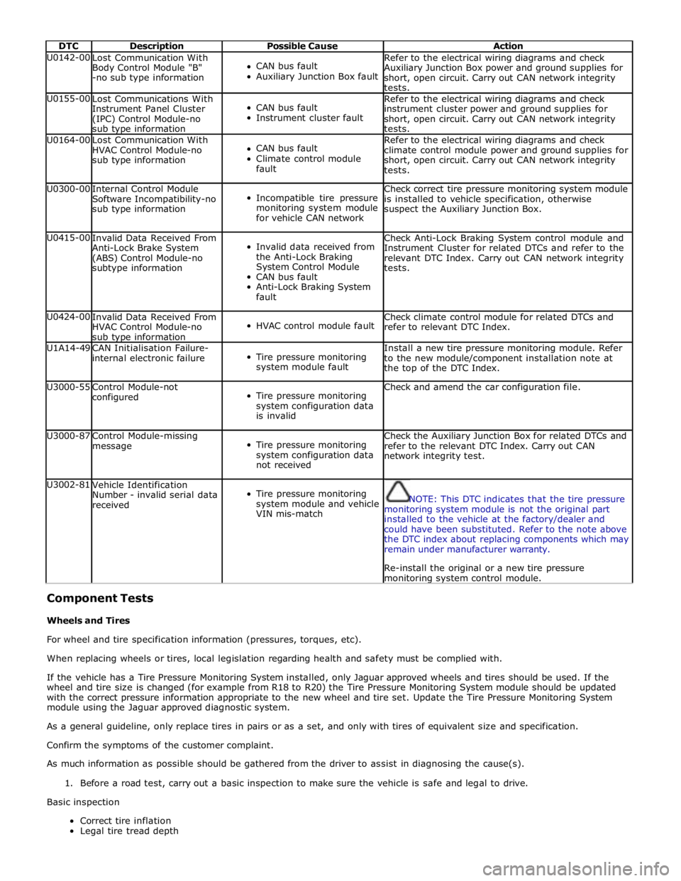
DTC Description Possible Cause Action U0142-00
Lost Communication With
Body Control Module "B"
-no sub type information
CAN bus fault
Auxiliary Junction Box fault Refer to the electrical wiring diagrams and check
Auxiliary Junction Box power and ground supplies for
short, open circuit. Carry out CAN network integrity
tests. U0155-00
Lost Communications With
Instrument Panel Cluster
(IPC) Control Module-no
sub type information
CAN bus fault
Instrument cluster fault Refer to the electrical wiring diagrams and check
instrument cluster power and ground supplies for
short, open circuit. Carry out CAN network integrity
tests. U0164-00
Lost Communication With
HVAC Control Module-no
sub type information
CAN bus fault
Climate control module
fault Refer to the electrical wiring diagrams and check
climate control module power and ground supplies for
short, open circuit. Carry out CAN network integrity
tests. U0300-00
Internal Control Module
Software Incompatibility-no
sub type information
Incompatible tire pressure
monitoring system module
for vehicle CAN network Check correct tire pressure monitoring system module
is installed to vehicle specification, otherwise
suspect the Auxiliary Junction Box. U0415-00
Invalid Data Received From
Anti-Lock Brake System
(ABS) Control Module-no
subtype information
Invalid data received from
the Anti-Lock Braking
System Control Module
CAN bus fault
Anti-Lock Braking System
fault Check Anti-Lock Braking System control module and
Instrument Cluster for related DTCs and refer to the
relevant DTC Index. Carry out CAN network integrity
tests. U0424-00
Invalid Data Received From
HVAC Control Module-no
sub type information
HVAC control module fault Check climate control module for related DTCs and
refer to relevant DTC Index. U1A14-49
CAN Initialisation Failure-
internal electronic failure
Tire pressure monitoring
system module fault Install a new tire pressure monitoring module. Refer
to the new module/component installation note at
the top of the DTC Index. U3000-55
Control Module-not
configured
Tire pressure monitoring
system configuration data
is invalid Check and amend the car configuration file. U3000-87
Control Module-missing
message
Tire pressure monitoring
system configuration data
not received Check the Auxiliary Junction Box for related DTCs and
refer to the relevant DTC Index. Carry out CAN
network integrity test. U3002-81
Vehicle Identification
Number - invalid serial data
received
Tire pressure monitoring
system module and vehicle
VIN mis-match
NOTE: This DTC indicates that the tire pressure
monitoring system module is not the original part
installed to the vehicle at the factory/dealer and
could have been substituted. Refer to the note above
the DTC index about replacing components which may
remain under manufacturer warranty.
Re-install the original or a new tire pressure monitoring system control module.
Component Tests
Wheels and Tires
For wheel and tire specification information (pressures, torques, etc).
When replacing wheels or tires, local legislation regarding health and safety must be complied with.
If the vehicle has a Tire Pressure Monitoring System installed, only Jaguar approved wheels and tires should be used. If the
wheel and tire size is changed (for example from R18 to R20) the Tire Pressure Monitoring System module should be updated
with the correct pressure information appropriate to the new wheel and tire set. Update the Tire Pressure Monitoring System
module using the Jaguar approved diagnostic system.
As a general guideline, only replace tires in pairs or as a set, and only with tires of equivalent size and specification.
Confirm the symptoms of the customer complaint.
As much information as possible should be gathered from the driver to assist in diagnosing the cause(s).
1. Before a road test, carry out a basic inspection to make sure the vehicle is safe and legal to drive.
Basic inspection
Correct tire inflation
Legal tire tread depth
Page 470 of 3039
Installation
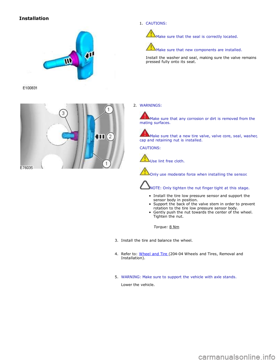
1. CAUTIONS:
Make sure that the seal is correctly located.
Make sure that new components are installed.
Install the washer and seal, making sure the valve remains
pressed fully onto its seat.
2. WARNINGS:
Make sure that any corrosion or dirt is removed from the
mating surfaces.
Make sure that a new tire valve, valve core, seal, washer,
cap and retaining nut is installed.
CAUTIONS:
Use lint free cloth.
Only use moderate force when installing the sensor.
NOTE: Only tighten the nut finger tight at this stage.
Install the tire low pressure sensor and support the
sensor body in position.
Support the back of the valve stem in order to prevent
rotation to the tire low pressure sensor body.
Gently push the nut towards the center of the wheel.
Tighten the nut.
Torque: 8 Nm
3. Install the tire and balance the wheel.
4. Refer to: Wheel and Tire (204-04 Wheels and Tires, Removal and Installation).
5. WARNING: Make sure to support the vehicle with axle stands.
Lower the vehicle.
Page 478 of 3039
Wheels and Tires - Wheel and Tire
Removal and Installation
Removal
NOTE: Removal steps in this procedure may contain installation details. Published: 11-May-2011
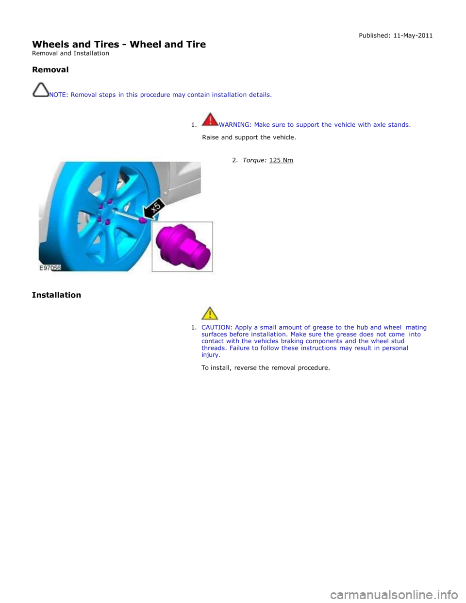
1. WARNING: Make sure to support the vehicle with axle stands.
Raise and support the vehicle.
Installation
2. Torque: 125 Nm
1. CAUTION: Apply a small amount of grease to the hub and wheel mating
surfaces before installation. Make sure the grease does not come into
contact with the vehicles braking components and the wheel stud
threads. Failure to follow these instructions may result in personal
injury.
To install, reverse the removal procedure.
Page 483 of 3039
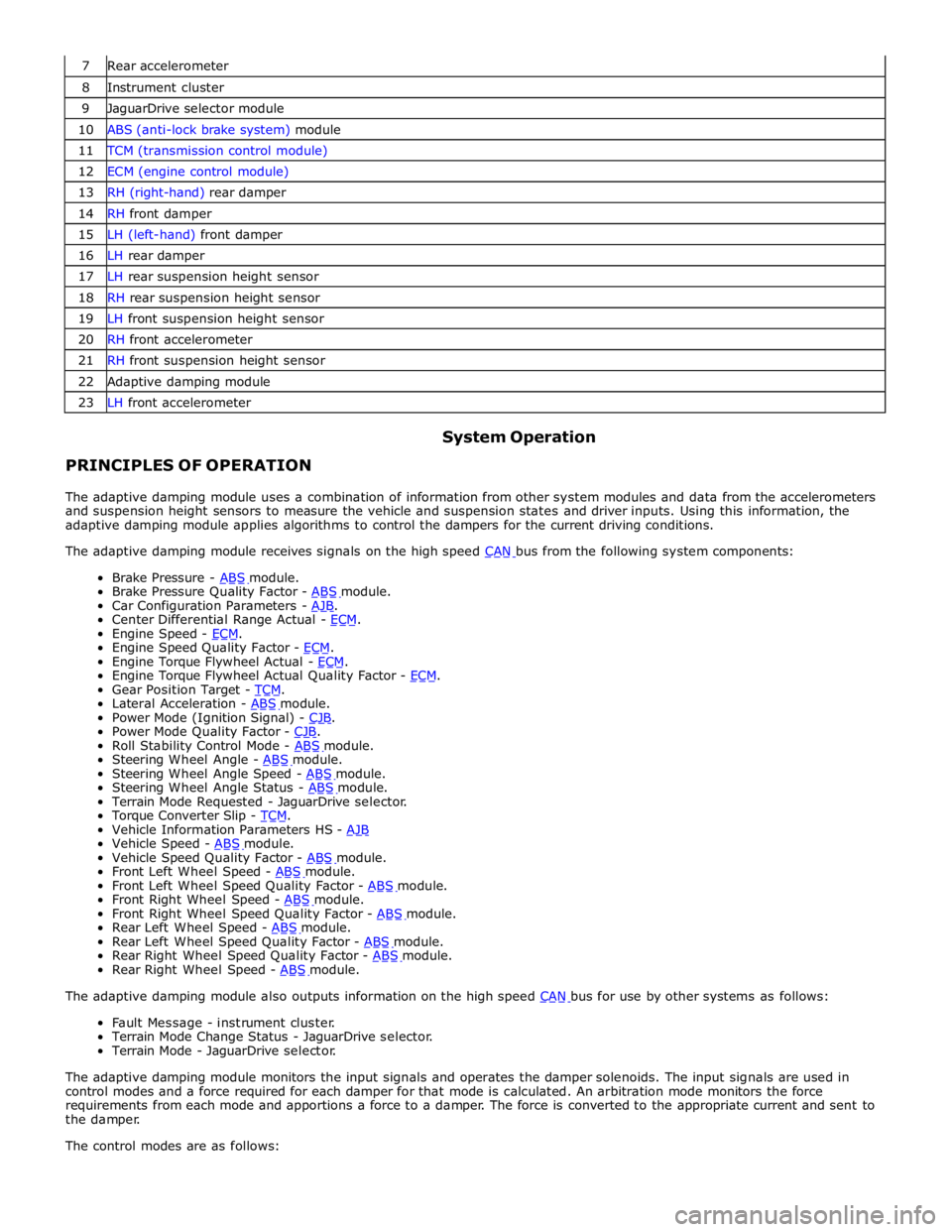
7 Rear accelerometer 8 Instrument cluster 9 JaguarDrive selector module 10 ABS (anti-lock brake system) module 11 TCM (transmission control module) 12 ECM (engine control module) 13 RH (right-hand) rear damper 14 RH front damper 15 LH (left-hand) front damper 16 LH rear damper 17 LH rear suspension height sensor 18 RH rear suspension height sensor 19 LH front suspension height sensor 20 RH front accelerometer 21 RH front suspension height sensor 22 Adaptive damping module 23 LH front accelerometer
PRINCIPLES OF OPERATION System Operation
The adaptive damping module uses a combination of information from other system modules and data from the accelerometers
and suspension height sensors to measure the vehicle and suspension states and driver inputs. Using this information, the
adaptive damping module applies algorithms to control the dampers for the current driving conditions.
The adaptive damping module receives signals on the high speed CAN bus from the following system components: Brake Pressure - ABS module. Brake Pressure Quality Factor - ABS module. Car Configuration Parameters - AJB. Center Differential Range Actual - ECM. Engine Speed - ECM. Engine Speed Quality Factor - ECM. Engine Torque Flywheel Actual - ECM. Engine Torque Flywheel Actual Quality Factor - ECM. Gear Position Target - TCM. Lateral Acceleration - ABS module. Power Mode (Ignition Signal) - CJB. Power Mode Quality Factor - CJB. Roll Stability Control Mode - ABS module. Steering Wheel Angle - ABS module. Steering Wheel Angle Speed - ABS module. Steering Wheel Angle Status - ABS module. Terrain Mode Requested - JaguarDrive selector.
Torque Converter Slip - TCM. Vehicle Information Parameters HS - AJB Vehicle Speed - ABS module. Vehicle Speed Quality Factor - ABS module. Front Left Wheel Speed - ABS module. Front Left Wheel Speed Quality Factor - ABS module. Front Right Wheel Speed - ABS module. Front Right Wheel Speed Quality Factor - ABS module. Rear Left Wheel Speed - ABS module. Rear Left Wheel Speed Quality Factor - ABS module. Rear Right Wheel Speed Quality Factor - ABS module. Rear Right Wheel Speed - ABS module. The adaptive damping module also outputs information on the high speed CAN bus for use by other systems as follows: Fault Message - instrument cluster.
Terrain Mode Change Status - JaguarDrive selector.
Terrain Mode - JaguarDrive selector.
The adaptive damping module monitors the input signals and operates the damper solenoids. The input signals are used in
control modes and a force required for each damper for that mode is calculated. An arbitration mode monitors the force
requirements from each mode and apportions a force to a damper. The force is converted to the appropriate current and sent to
the damper.
The control modes are as follows:
Page 491 of 3039
Published: 11-May-2011
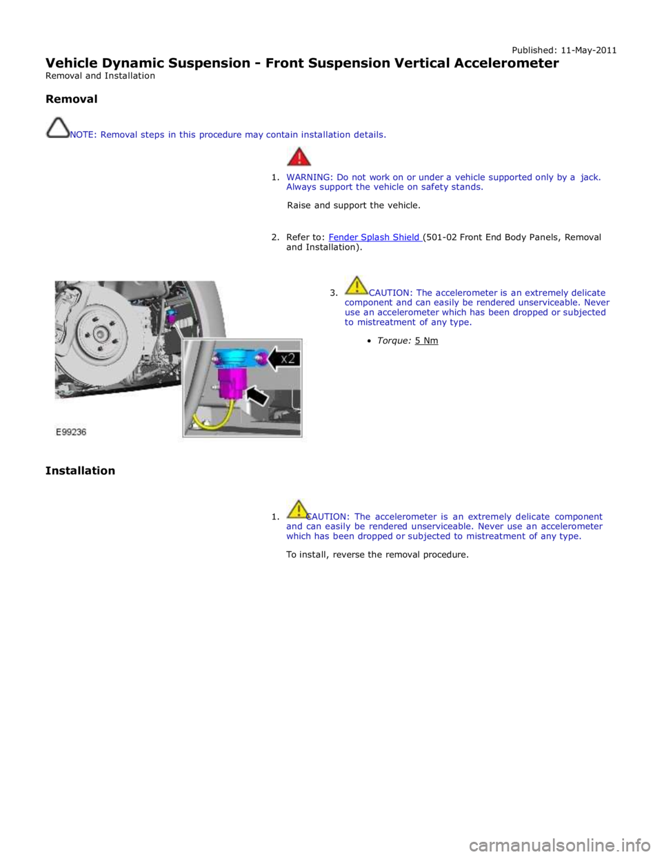
Vehicle Dynamic Suspension - Front Suspension Vertical Accelerometer
Removal and Installation
Removal
NOTE: Removal steps in this procedure may contain installation details.
1. WARNING: Do not work on or under a vehicle supported only by a jack.
Always support the vehicle on safety stands.
Raise and support the vehicle.
2. Refer to: Fender Splash Shield (501-02 Front End Body Panels, Removal and Installation).
Installation
3. CAUTION: The accelerometer is an extremely delicate
component and can easily be rendered unserviceable. Never
use an accelerometer which has been dropped or subjected
to mistreatment of any type.
Torque: 5 Nm
1. CAUTION: The accelerometer is an extremely delicate component
and can easily be rendered unserviceable. Never use an accelerometer
which has been dropped or subjected to mistreatment of any type.
To install, reverse the removal procedure.
Page 492 of 3039
Published: 11-May-2011
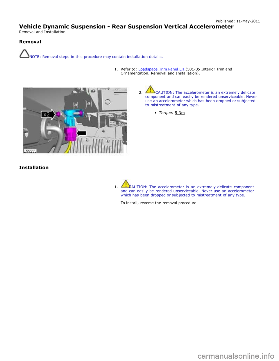
Vehicle Dynamic Suspension - Rear Suspension Vertical Accelerometer
Removal and Installation
Removal
NOTE: Removal steps in this procedure may contain installation details.
1. Refer to: Loadspace Trim Panel LH (501-05 Interior Trim and Ornamentation, Removal and Installation).
Installation
2. CAUTION: The accelerometer is an extremely delicate
component and can easily be rendered unserviceable. Never
use an accelerometer which has been dropped or subjected
to mistreatment of any type.
Torque: 5 Nm
1. CAUTION: The accelerometer is an extremely delicate component
and can easily be rendered unserviceable. Never use an accelerometer
which has been dropped or subjected to mistreatment of any type.
To install, reverse the removal procedure.
Page 495 of 3039
Published: 11-May-2011
Ride and Handling Optimization - Ride and Handling Optimization - System
Operation and Component Description
Description and Operation
JAGUARDRIVE CONTROL OPERATION
Engine Management System System Operation
The Engine Management System (EMS) varies the accelerator pedal maps to change the amount of torque per percentage of
pedal travel. The EMS can also change the accelerator pedal response to control the allowed torque change relative to the
speed of pedal travel.
Each driving mode uses a combination of operating parameters for each sub-system. Changing between driving modes initiates
a different set of operating characteristics, which will be noticeable to the driver. The driver will notice differences in engine
response when, for example, the accelerator pedal is held in a constant position and the driving mode is changed from Winter
to Dynamic, the driver will notice the torque and engine speed increase. Similarly, if the mode is changed from Normal or
Dynamic to Winter the driver will notice a reduction in torque and engine speed.
NOTE: The change in torque and engine speed can take approximately 30 seconds and care must be taken not to confuse
the JaguarDrive Control system operation with an EMS fault.
Transmission Control
The TCM (transmission control module) changes the shift maps for the JaguarDrive Control mode selected. This changes the
shift points providing early or late upshifts and downshifts. For example, on slippery surfaces in Winter mode the transmission
will select 2nd gear for starting from a standstill on a flat surface to minimize wheel slip.
Anti-lock Braking System Control
The ABS (anti-lock brake system) module controls several vehicle functions and adjusts the operating parameters of these
functions to optimize the selected JaguarDrive Control mode. Traction control uses different slip/acceleration thresholds to
improve traction and vehicle composure. For example, the system sensitivity is increased on slippery surfaces to reduce wheel
spin.
If TracDSC is selected or DSC is switched off, then subsequently the JaguarDrive Control mode is changed, DSC is automatically
switched back on (or to TracDSC for Dynamic mode).
The stability control uses different threshold values for the selected mode, reducing the requirement for the driver to change
the DSC system mode for optimum performance in various driving scenarios.
Incorrect Mode Usage
Selection of an inappropriate mode is discouraged in the following ways:
The active mode icon is continually displayed in the instrument cluster message center
In any special mode, when the ignition has been in the off position continuously for more than 6 hours, the JaguarDrive
Control system defaults to the special modes off (DSC on).
Selection of an inappropriate mode for the conditions will not endanger the driver or immediately cause damage to the vehicle.
Continued use of an inappropriate mode may reduce the life of some components. The driver may notice a different vehicle
response, with the engine and transmission responses being different than in the special modes off.
Driver Information
The instrument cluster contains a message center, which displays vehicle information to the driver. The message center
contains the JaguarDrive Control mode icons, which display the currently selected mode. If no symbol is displayed, no special
mode is selected and the system is in special modes off.
Any required changes to the subsystems are also passed to the driver in the form of warning illumination in the instrument
cluster or appropriate messages in the message center, DSC off for example.
In Dynamic mode when the transmission is in manual mode, the gear information is displayed in amber when the appropriate
engine speed is reached for optimum sporty change point.
DIAGNOSTICS
JaguarDrive Control relies on the correct functionality of the sub-systems. If one of the sub-systems develops a fault, the
JaguarDrive Control system will not function, even though the fault is not in the JaguarDrive Control system.
The JaguarDrive Selector module and rotary control should only be investigated if there are no apparent faults in any of the
sub-systems. If a fault in a sub-system is subsequently corrected, the JaguarDrive Control system will function normally after
an ignition on and off cycle.
Page 524 of 3039
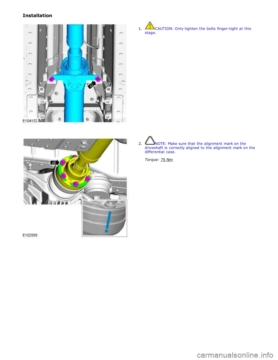
Installation
1. CAUTION: Only tighten the bolts finger-tight at this
stage.
2. NOTE: Make sure that the alignment mark on the
driveshaft is correctly aligned to the alignment mark on the
differential case.
Torque: 75 Nm
Page 525 of 3039
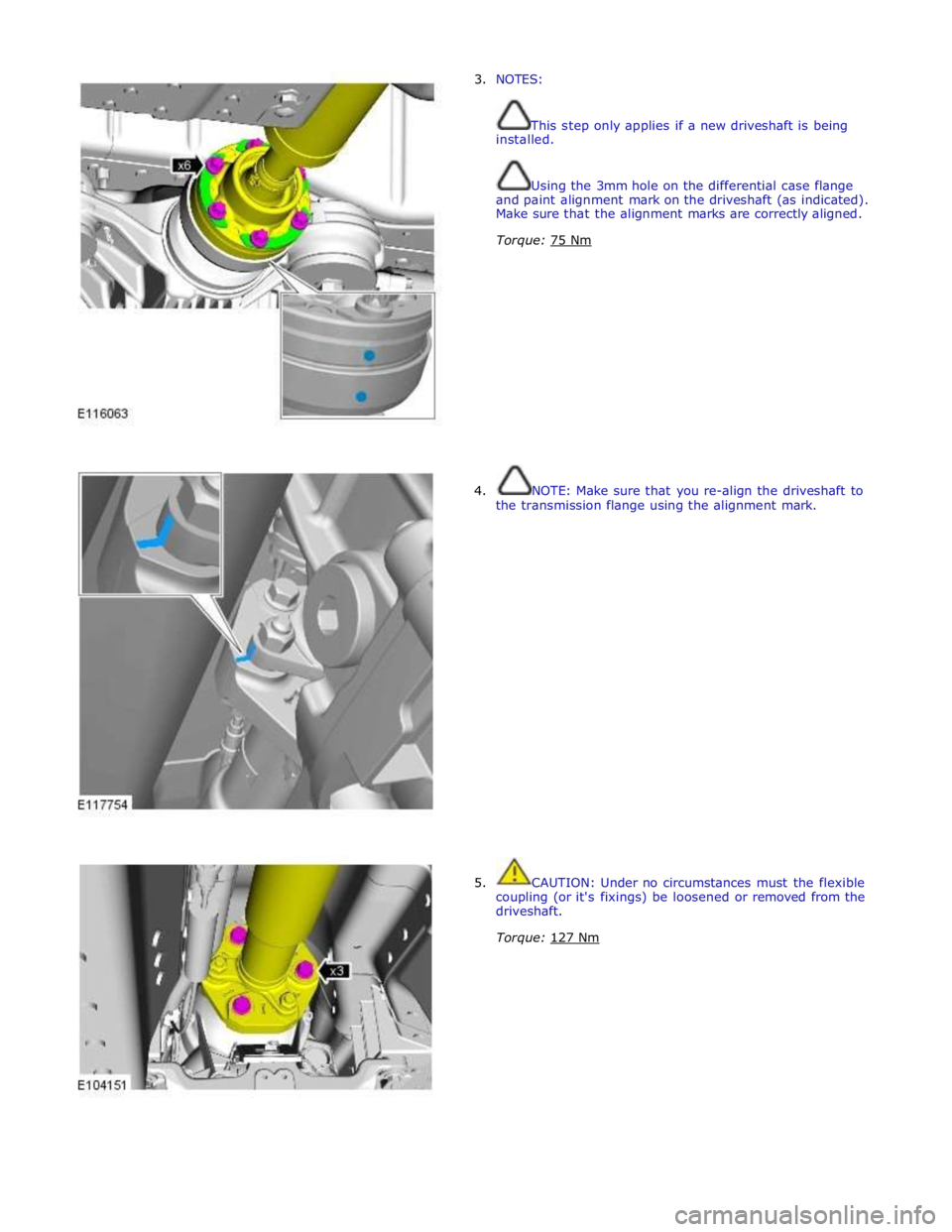
3. NOTES:
This step only applies if a new driveshaft is being
installed.
Using the 3mm hole on the differential case flange
and paint alignment mark on the driveshaft (as indicated).
Make sure that the alignment marks are correctly aligned.
Torque: 75 Nm
4. NOTE: Make sure that you re-align the driveshaft to
the transmission flange using the alignment mark.
5. CAUTION: Under no circumstances must the flexible
coupling (or it's fixings) be loosened or removed from the
driveshaft.
Torque: 127 Nm