JAGUAR XFR 2010 1.G Owner's Manual
XFR 2010 1.G
JAGUAR
JAGUAR
https://www.carmanualsonline.info/img/21/7642/w960_7642-0.png
JAGUAR XFR 2010 1.G Owner's Manual
Page 373 of 3039
Published: 11-May-2011
Front Suspension - Front Wheel Bearing and Wheel Hub TDV6 3.0L Diesel /V8 5.0L Petrol/V8 S/C 5.0L Petrol
Removal and Installation
Removal
NOTE: Removal steps in this procedure may contain installation details.
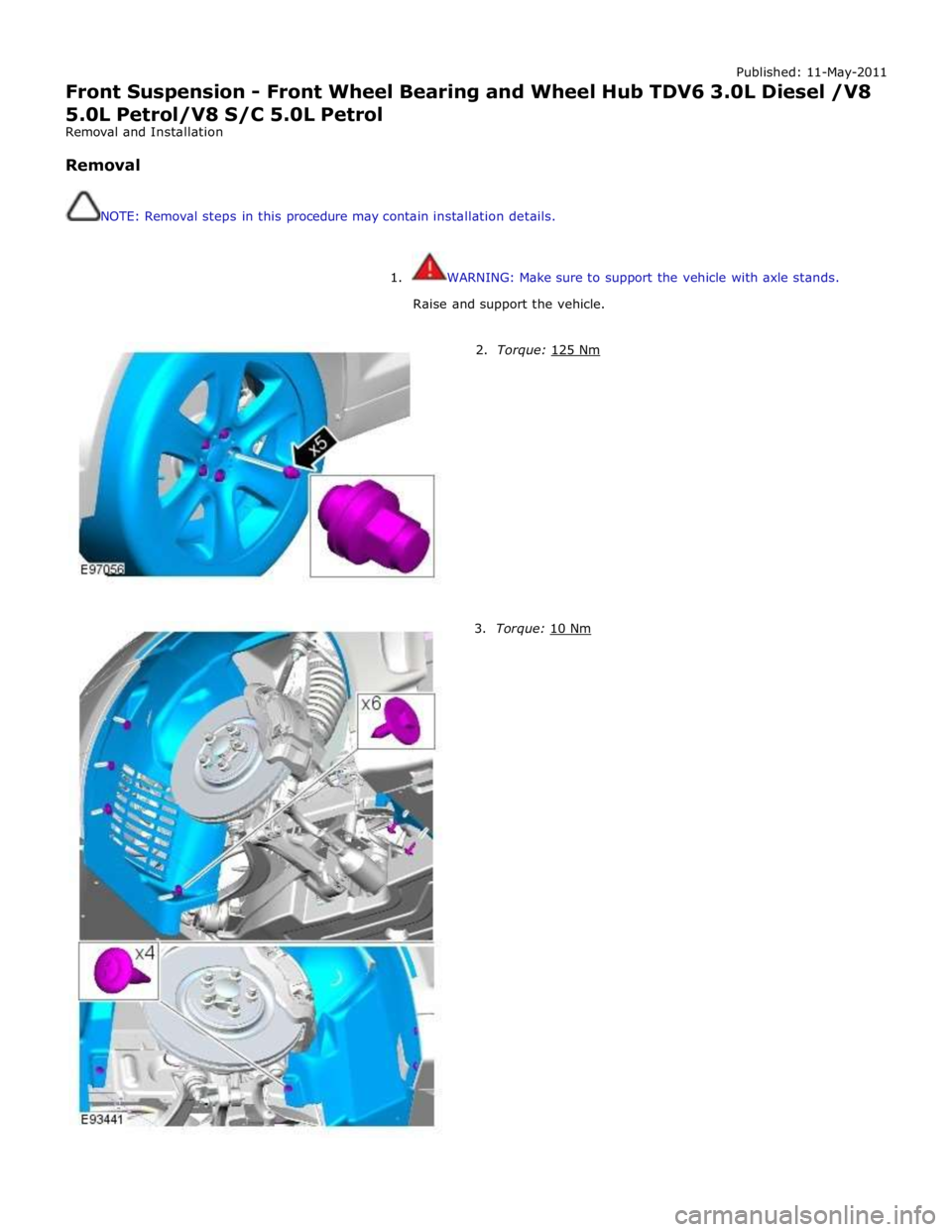
1. WARNING: Make sure to support the vehicle with axle stands.
Raise and support the vehicle.
2. Torque: 125 Nm 3. Torque: 10 Nm
Page 374 of 3039
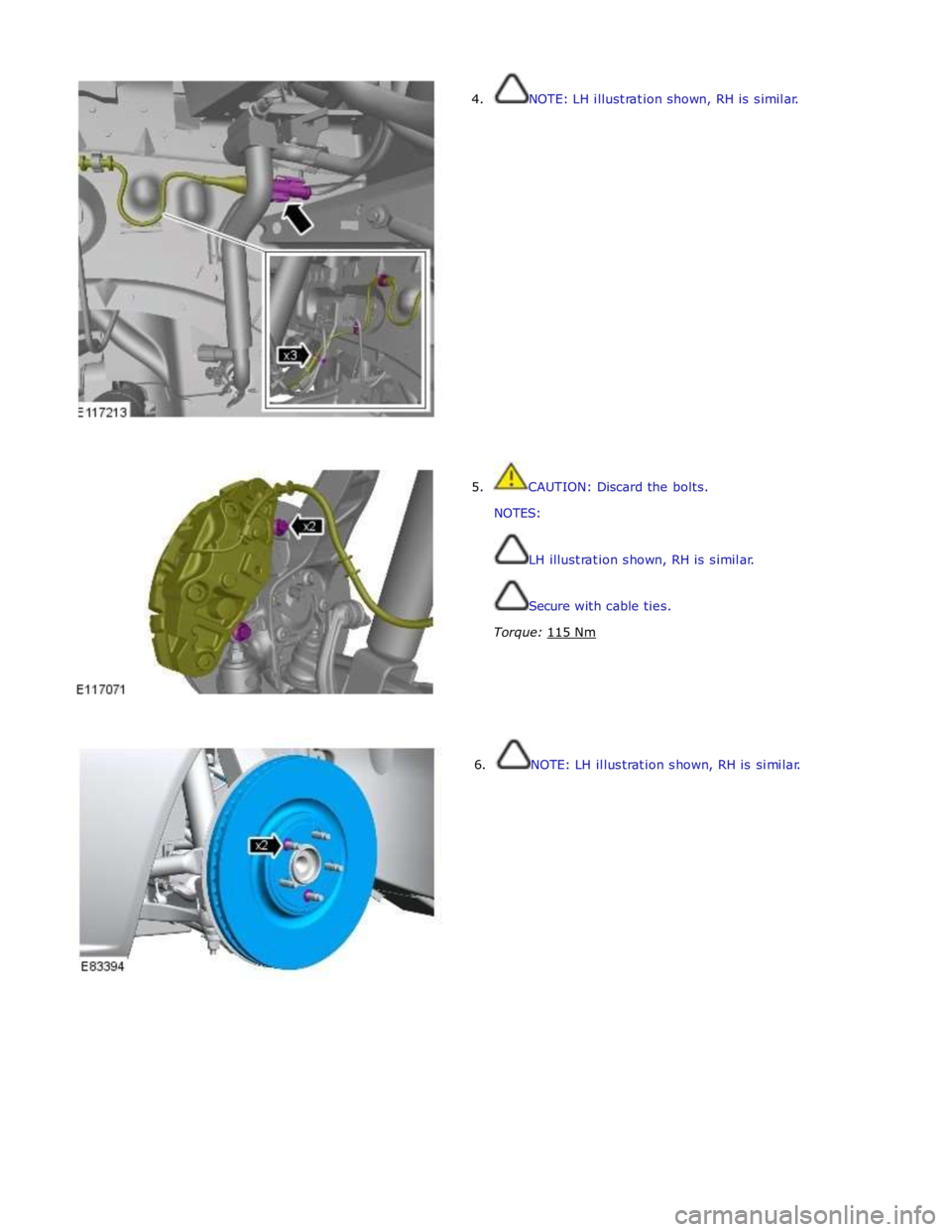
4. NOTE: LH illustration shown, RH is similar.
5. CAUTION: Discard the bolts.
NOTES:
LH illustration shown, RH is similar.
Secure with cable ties.
Torque: 115 Nm
6. NOTE: LH illustration shown, RH is similar.
Page 375 of 3039
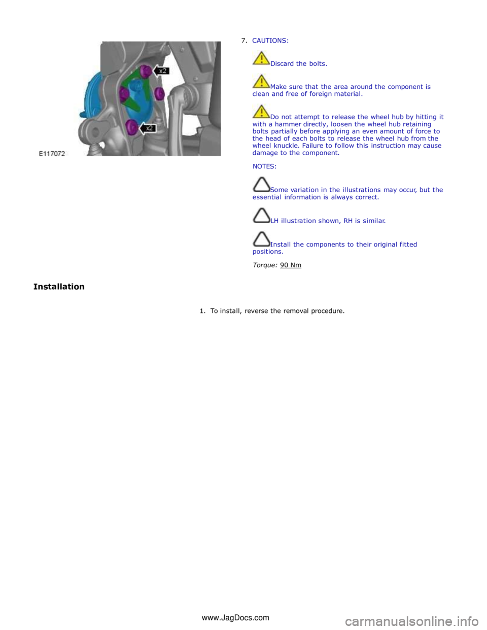
7. CAUTIONS:
Discard the bolts.
Make sure that the area around the component is
clean and free of foreign material.
Do not attempt to release the wheel hub by hitting it
with a hammer directly, loosen the wheel hub retaining
bolts partially before applying an even amount of force to
the head of each bolts to release the wheel hub from the
wheel knuckle. Failure to follow this instruction may cause
damage to the component.
NOTES:
Some variation in the illustrations may occur, but the
essential information is always correct.
LH illustration shown, RH is similar.
Install the components to their original fitted
positions.
Torque: 90 Nm
Installation
1. To install, reverse the removal procedure. www.JagDocs.com
Page 403 of 3039
Interior Trim and Ornamentation, Removal and Installation).
Vehicles with active damping
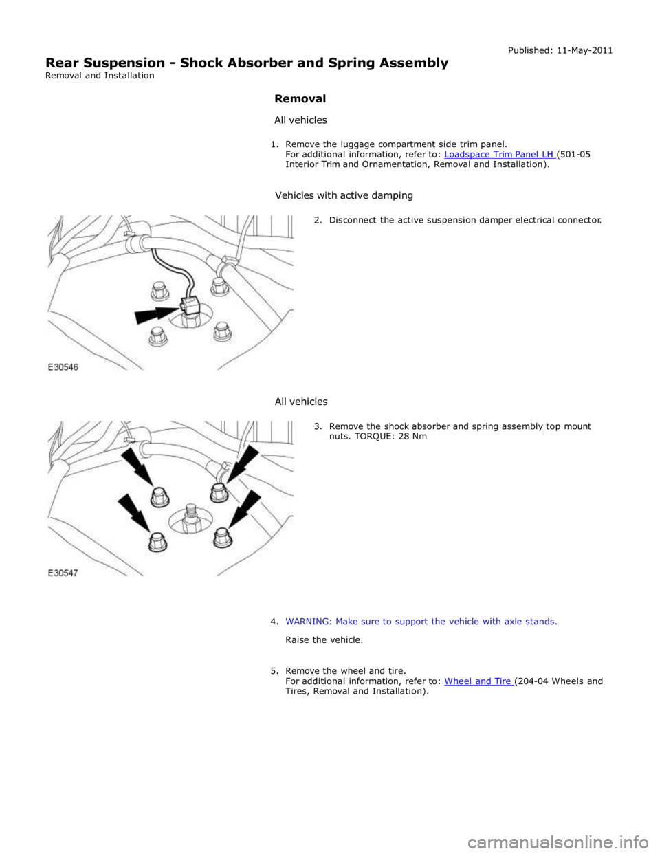
2. Disconnect the active suspension damper electrical connector.
All vehicles
3. Remove the shock absorber and spring assembly top mount
nuts. TORQUE: 28 Nm
4. WARNING: Make sure to support the vehicle with axle stands.
Raise the vehicle.
5. Remove the wheel and tire.
For additional information, refer to: Wheel and Tire (204-04 Wheels and Tires, Removal and Installation).
Page 404 of 3039
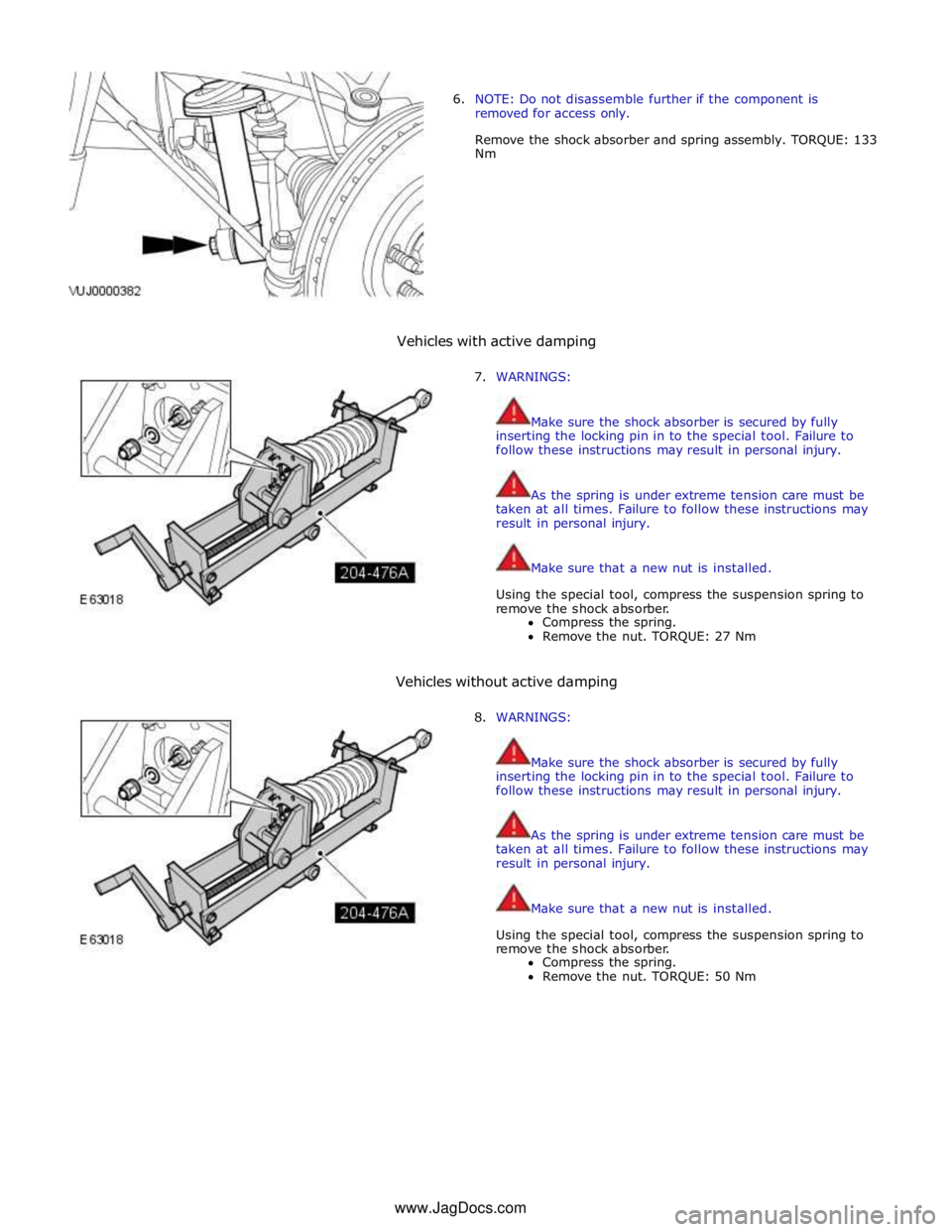
6. NOTE: Do not disassemble further if the component is
removed for access only.
Remove the shock absorber and spring assembly. TORQUE: 133
Nm
Vehicles with active damping
7. WARNINGS:
Make sure the shock absorber is secured by fully
inserting the locking pin in to the special tool. Failure to
follow these instructions may result in personal injury.
As the spring is under extreme tension care must be
taken at all times. Failure to follow these instructions may
result in personal injury.
Make sure that a new nut is installed.
Using the special tool, compress the suspension spring to
remove the shock absorber.
Compress the spring.
Remove the nut. TORQUE: 27 Nm
Vehicles without active damping
8. WARNINGS:
Make sure the shock absorber is secured by fully
inserting the locking pin in to the special tool. Failure to
follow these instructions may result in personal injury.
As the spring is under extreme tension care must be
taken at all times. Failure to follow these instructions may
result in personal injury.
Make sure that a new nut is installed.
Using the special tool, compress the suspension spring to
remove the shock absorber.
Compress the spring.
Remove the nut. TORQUE: 50 Nm
www.JagDocs.com
Page 428 of 3039
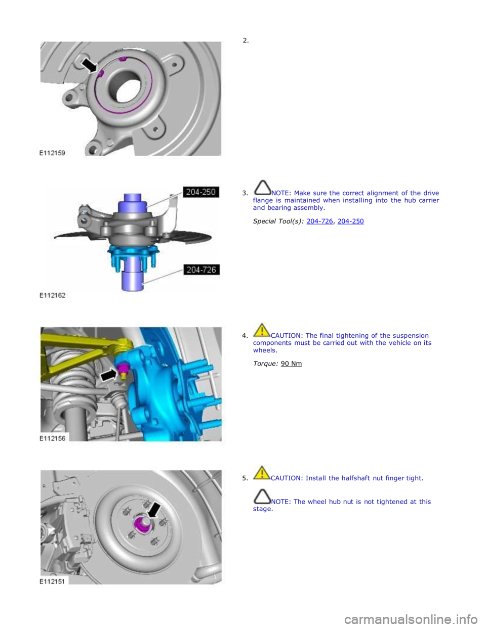
2.
3. NOTE: Make sure the correct alignment of the drive
flange is maintained when installing into the hub carrier
and bearing assembly.
Special Tool(s): 204-726, 204-250
4. CAUTION: The final tightening of the suspension
components must be carried out with the vehicle on its
wheels.
Torque: 90 Nm
5. CAUTION: Install the halfshaft nut finger tight.
NOTE: The wheel hub nut is not tightened at this
stage.
Page 429 of 3039
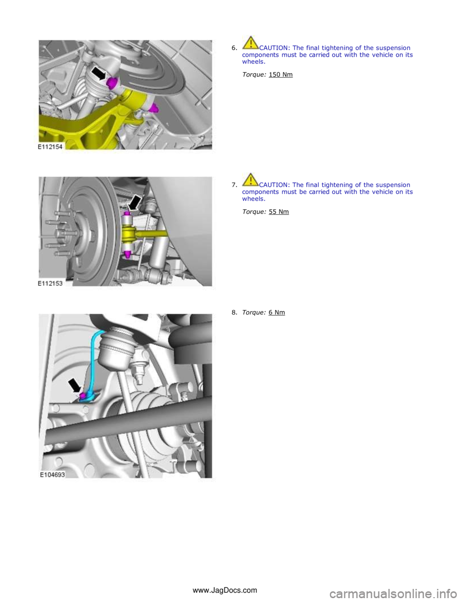
6. CAUTION: The final tightening of the suspension
components must be carried out with the vehicle on its
wheels.
Torque: 150 Nm
7. CAUTION: The final tightening of the suspension
components must be carried out with the vehicle on its
wheels.
Torque: 55 Nm
8. Torque: 6 Nm www.JagDocs.com
Page 430 of 3039
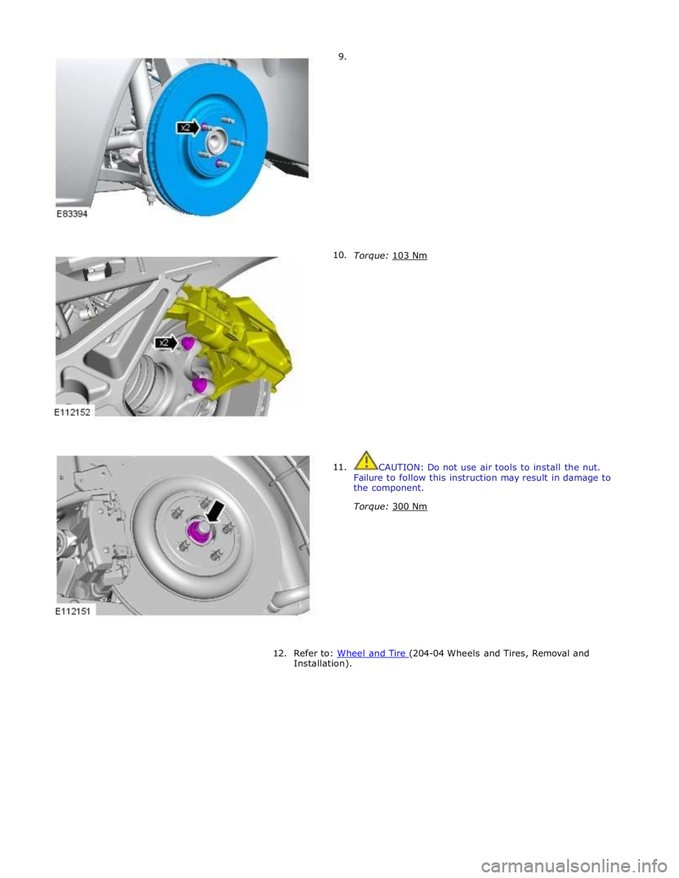
9.
10.
11.
Torque: 103 Nm
CAUTION: Do not use air tools to install the nut.
Failure to follow this instruction may result in damage to
the component.
Torque: 300 Nm
12. Refer to: Wheel and Tire (204-04 Wheels and Tires, Removal and Installation).
Page 432 of 3039
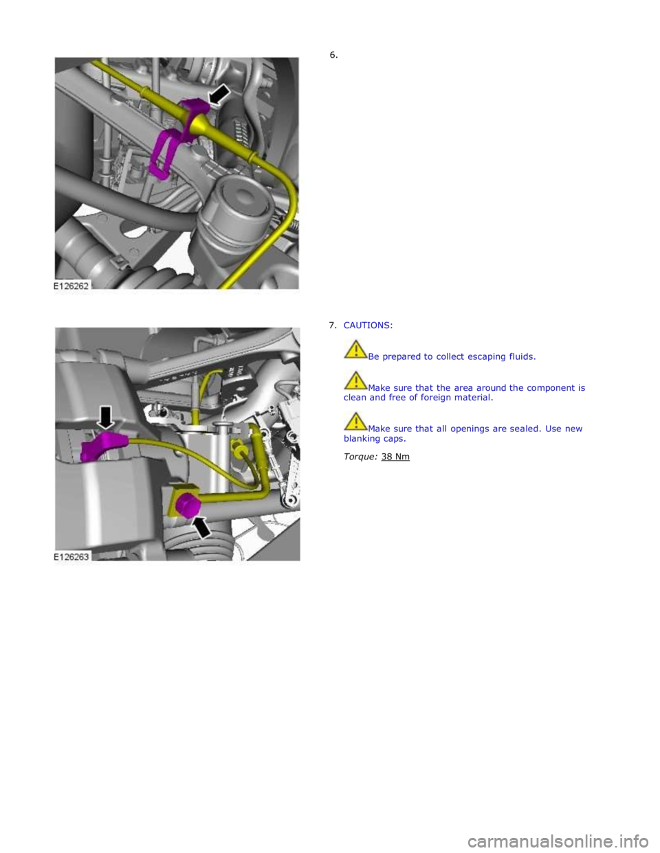
6.
7. CAUTIONS:
Be prepared to collect escaping fluids.
Make sure that the area around the component is
clean and free of foreign material.
Make sure that all openings are sealed. Use new
blanking caps.
Torque: 38 Nm
Page 433 of 3039
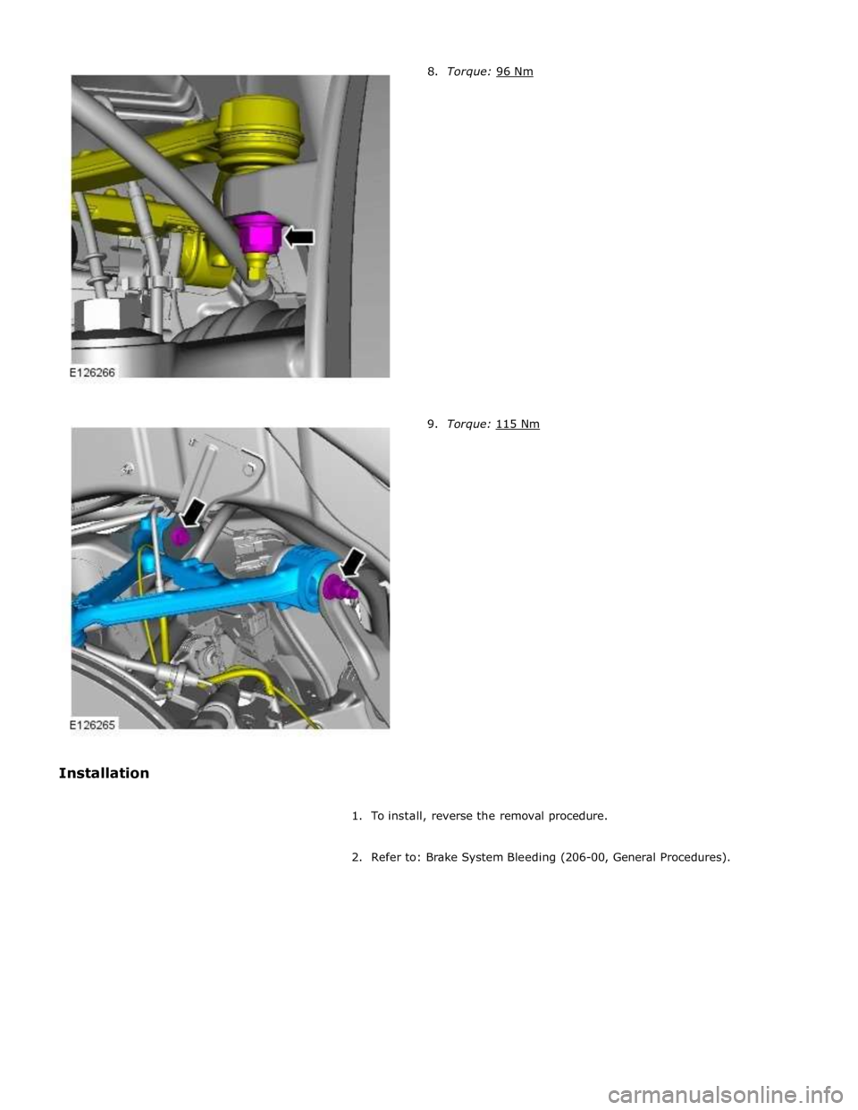
9. Torque: 115 Nm
1. To install, reverse the removal procedure.
2. Refer to: Brake System Bleeding (206-00, General Procedures).
