Engine JAGUAR XFR 2010 1.G Workshop Manual
[x] Cancel search | Manufacturer: JAGUAR, Model Year: 2010, Model line: XFR, Model: JAGUAR XFR 2010 1.GPages: 3039, PDF Size: 58.49 MB
Page 1531 of 3039
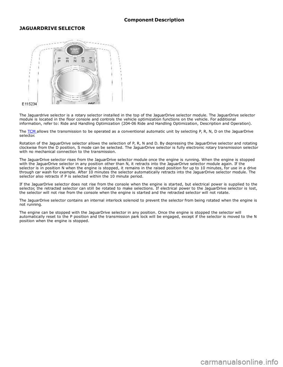
selector.
Rotation of the JaguarDrive selector allows the selection of P, R, N and D. By depressing the JaguarDrive selector and rotating
clockwise from the D position, S mode can be selected. The JaguarDrive selector is fully electronic rotary transmission selector
with no mechanical connection to the transmission.
The JaguarDrive selector rises from the JaguarDrive selector module once the engine is running. When the engine is stopped
with the JaguarDrive selector in any position other than N, it retracts into the JaguarDrive selector module again. If the
selector is in position N when the engine is stopped, it remains in the raised position for up to 10 minutes, for use in a drive
through car wash for example. After 10 minutes the selector automatically retracts into the JaguarDrive selector module. The
selector also retracts if P is selected within the 10 minute period.
If the JaguarDrive selector does not rise from the console when the engine is started, but electrical power is supplied to the
selector, the retracted selector can still be rotated to make selections. If electrical power to the JaguarDrive selector is lost,
the selector will not rise from the console when the engine is started and the retracted selector will not rotate.
The JaguarDrive selector contains an internal interlock solenoid to prevent the selector from being rotated when the engine is
not running.
The engine can be stopped with the JaguarDrive selector in any position. Once the engine is stopped the selector will
automatically reset to the P position and the transmission park lock will be engaged, except if the selector is moved to the N
position when the engine is stopped.
Page 1538 of 3039

Published: 11-May-2011
Automatic Transmission/Transaxle External Controls - V6 3.0L Petrol -
Transmission Control Switch (TCS) Knob
Removal and Installation
Removal
NOTE: Removal steps in this procedure may contain inst allation details.
Start the engine and make sure that 'P' is selected.1.T orque: 2 Nm 2.
Installation
To inst all, reverse t he removal procedure. 1.www.JagDocs.com
Page 1539 of 3039

Published: 11-May-2011
Automatic Transmission/Transaxle External Controls - V6 3.0L Petrol -
Emergency Park Position Release Lever
Removal and Installation
Removal
NOTE: Removal steps in this procedure may contain inst allation details.
Refer to: Batt ery Disconnect and Connect (414-01 Battery, Mounting and
Cables, General Procedures). 1.
Refer to: Air Deflector (501-02, Removal and Installation). 2.
Refer to: Engine Rear Undershield (501-02 Front End Body Panels,
Removal and Installation). 3.
Refer to: Floor Console Side Trim Panel (501-12 Inst rument Panel and
Console, Removal and Installation). 4.WARNING: Make sure to support the vehicle with axle
stands.
T orque: 11 Nm 5.
Page 1546 of 3039

Published: 11-May-2011
Exhaust System - V8 5.0L Petrol/V8 S/C 5.0L Petrol - Exhaust System - Overview
Description and Operation
OVERVIEW
5.0L V8 NATURALLY ASPIRATED AND SUPERCHARGER - FROM 2010MY
The exhaust system fitted to models with the 5.0L V8 engines are fabricated from stainless steel. 5 separate assemblies make
up the complete system.
The front section comprises 2 separate assemblies (LH (left-hand) and RH (right-hand)) incorporating a catalytic converter for
each bank of cylinders. The rear section comprises 3 separate sections; a center section and two rear sections. The center
section assembly incorporates a rear silencer which is connected to a center resonator silencer. On supercharger models, the
center resonator is a one piece assembly with two inlet pipes from the center silencer and two outlet pipes to the rear
silencers. On naturally aspirated models, each outlet pipe from the center silencer connects into an individual center resonator.
The system is attached to the underside of the body with mounting rubbers which are located on steel hanger bars that are
welded to the system. The mounting rubbers locate on corresponding hangers which are welded or bolted to the underside of
the vehicle body.
Page 1547 of 3039
Published: 28-Apr-2014
Exhaust System - V8 5.0L Petrol/V8 S/C 5.0L Petrol - Exhaust System - System Operation and Component Description
Description and Operation
CATALYTIC CONVERTERS System Operation
In the catalytic converters, the exhaust gases are passed through honeycombed ceramic elements coated with a special
surface treatment called 'washcoat'. The washcoat increases the surface area of the ceramic elements by a factor of
approximately 7000. On top of the washcoat is a coating containing palladium and rhodium, which are the active constituents
for converting harmful emissions into inert by-products. The palladium and rhodium add oxygen to the carbon monoxide and
the hydrocarbons in the exhaust gases, to convert them into carbon dioxide and water respectively.
SEMI-ACTIVE MUFFLER VALVE (5.0L SUPERCHARGER VEHICLES ONLY)
The semi-active muffler valve is operated by the pressure in the exhaust system. At low engine speeds the valve head is
closed or partially closed to provide a more refined noise quality. At higher engine speeds the increased pressure within the
exhaust system opens the valve head to provide a more sporting noise. This is achieved by the valve, which once open, allows
the exhaust gasses to by-pass the baffle tubes and plates in the rear silencer.
Component Description
FRONT SECTION - 4.2L NATURALLY ASPIRATED (NAS ONLY) - From 2010MY
The front section comprises two separate pipes, each incorporating a catalytic converter. Each catalytic converter has a welded
inlet pipe with a flange. The inlet pipe is flared into a cone which mates with the exhaust manifold. The flange has two holes
which locate on studs in the exhaust manifold and is secured with flanged nuts. Each catalytic converter is fitted with a pre
and post catalyst HO2S (heated oxygen sensor).
Each catalytic converter has a curved outlet pipe which mates with the respective inlet pipe for the applicable resonator on the
center section. The joint on each pipe is secured with a clamp.
FRONT SECTION - 5.0L NATURALLY ASPIRATED AND SUPERCHARGER - From 2010MY
The front section is common to both the naturally aspirated and supercharger vehicles. The front section comprises two
separate pipes each incorporating a catalytic converter. Each catalytic converter has a welded pipe with a flange, which is
flared into a cone which mates with the exhaust manifold. Each flange has two holes which locate on studs in the exhaust
manifold and are secured with nuts. Each catalytic converter is fitted with a mid catalyst HO2S. The mid catalyst HO2S is located in the catalytic converter.
NOTE: The pre catalyst HO2S is located in the exhaust manifold.
On vehicles from 2013MY, a post catalyst HO2S is located in the curved pipe from each catalytic converter.
A curved pipe from each catalytic converter locates into the resonator inlet pipes of the center section. The LH (left-hand) pipe
is fitted with a mass damper which absorbs resonance from the system.
REAR SECTION - 4.2L NATURALLY ASPIRATED (NAS ONLY) - From 2010MY
The 2 inlet pipes each connect into a separate resonator silencer. Each resonator silencer is cylindrical in shape and houses 2
perforated tubes separated by 2 baffle plates. Exhaust gasses exit each resonator silencer via an outlet pipe. The 2 outlet
pipes are joined together behind the resonators with a cross over pipe. Each pipe also has a welded hanger bracket which
allow the rear section to be supported on mounting rubbers. A further bracket is welded to each pipe which braces the 2 pipes
together.
The 2 rear silencers each have a welded inlet pipe which mate with the outlet pipes from the resonator silencers and are each
secured with a clamp. The inlet pipes each have a welded hanger bracket which support each rear silencer at the rear of the
vehicle on mounting rubbers. The fabricated rear silencers have 2 perforated tubes which are supported on 2 perforated baffle
plates. The exhaust gasses are expelled from the rear silencer via a single outlet pipe. The outlet pipe from each silencer has
a welded hanger bar which support the rear silencer on mounting rubbers. The outlet pipe is fitted with a welded outlet which
is covered with a polished stainless steel finisher which is part welded to the silencer.
REAR SECTION - 5.0L NATURALLY ASPIRATED - From 2010MY
The 2 pipes from the front section each connect into 2 short pipes on the center resonator box and are secured with clamps.
Two pipes from the resonator box split the system into 2 sections which each connect into another resonator. Each resonator
silencer houses perforated tubes separated by baffle plates. Exhaust gasses exit each resonator silencer via an outlet pipe.
The 2 outlet pipes are joined together behind the resonators with a cross over pipe. Each pipe also has a welded hanger
bracket which allow the rear section to be supported on mounting rubbers. A further bracket is welded to each pipe which
braces the 2 pipes together.
The 2 rear silencers each have a welded inlet pipe which mate with the outlet pipes from the cylindrical resonator silencers and
www.JagDocs.com
Page 1549 of 3039
Published: 11-May-2011
Exhaust System - V8 5.0L Petrol/V8 S/C 5.0L Petrol - Exhaust System
Diagnosis and Testing
Principle of Operation
For a detailed description of the exhaust system, refer to the relevant Description and Operation section of the workshop
manual. REFER to: (309-00C Exhaust System - V8 5.0L Petrol/V8 S/C 5.0L Petrol)
Exhaust System (Description and Operation), Exhaust System (Description and Operation), Exhaust System (Description and Operation).
Inspection and Verification
CAUTION: Diagnosis by substitution from a donor vehicle is NOT acceptable. Substitution of control modules does not
guarantee confirmation of a fault and may also cause additional faults in the vehicle being checked and/or the donor vehicle.
NOTE: Check and rectify basic faults before beginning diagnostic routines involving pinpoint tests.
1. Verify the customer concern.
2. Visually inspect for obvious signs of damage and system integrity.
3. If an obvious cause for an observed or reported concern is found, correct the cause (if possible) before proceeding to
the next step.
4. If the cause is not visually evident, verify the symptom and refer to the Symptom Chart, alternatively check for
Diagnostic Trouble Codes (DTCs) and refer to the DTC Index.
Symptom Chart
Symptom Possible Causes Action Excessively
noisy/leaking
exhaust
Exhaust
system/components Inspect exhaust system. Rectify leaks and install new components as
required. Refer to Removal and Installation instructions in this section Loss of power
Restricted exhaust system
Exhaust sound
enhancement valve stuck
closed
Fuel system
Ignition system
Electronic engine control Inspect exhaust system. Install new exhaust components as required.
Refer to Removal and Installation instructions in this section. Check for
fuel, ignition and electronic engine control system DTCs and refer to the
relevant DTC Index
DTC Index
For a list of Diagnostic Trouble Codes (DTCs) that could be logged in the Engine Control Module (ECM), please refer to Section
303-14. REFER to:
Electronic Engine Controls (303-14C Electronic Engine Controls - V8 5.0L Petrol, Diagnosis and Testing), Electronic Engine Controls (303-14D Electronic Engine Controls - V8 S/C 5.0L Petrol, Diagnosis and Testing). Mechanical
Leaks
Metal fatigue
Pipes
Catalytic converter
Muffler(s)
Joints
Mountings
Clearance around components Visual Inspection
Page 1550 of 3039
Published: 11-May-2011
Exhaust System - V8 5.0L Petrol/V8 S/C 5.0L Petrol - Catalytic Converter LH
Removal and Installation
Removal
NOTE: Removal steps in this procedure may contain installation details.
1. Refer to: Battery Disconnect and Connect (414-01 Battery, Mounting and Cables, General Procedures).
2. WARNINGS:
Make sure to support the vehicle with axle stands.
Observe due care when working near a hot exhaust system.
Raise and support the vehicle.
3. Refer to: Air Deflector (501-02 Front End Body Panels, Removal and Installation).
4. Refer to: Engine Rear Undershield (501-02 Front End Body Panels, Removal and Installation).
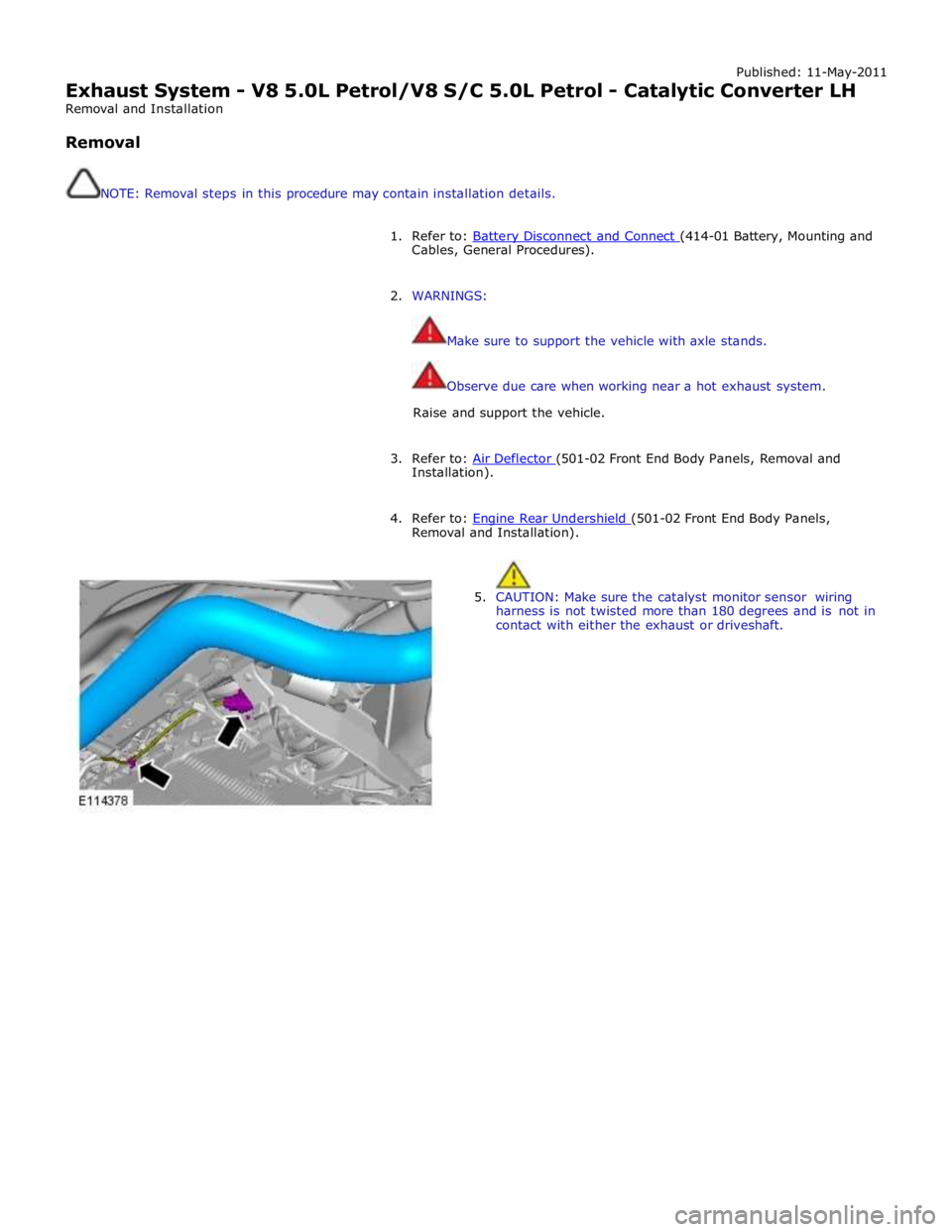
5. CAUTION: Make sure the catalyst monitor sensor wiring
harness is not twisted more than 180 degrees and is not in
contact with either the exhaust or driveshaft.
Page 1552 of 3039
2. NOTE: For NAS vehicles only.
If required, carry out a long drive cycle.
Refer to: Powertrain Control Module (PCM) Long Drive Cycle Self-Test (303-14D Electronic Engine Controls - V8 S/C 5.0L Petrol, General
Procedures).
www.JagDocs.com
Page 1553 of 3039
Published: 11-May-2011
Exhaust System - V8 5.0L Petrol/V8 S/C 5.0L Petrol - Catalytic Converter RH
Removal and Installation
Removal
NOTE: Removal steps in this procedure may contain installation details.
1. Refer to: Battery Disconnect and Connect (414-01 Battery, Mounting and Cables, General Procedures).
2. WARNINGS:
Make sure to support the vehicle with axle stands.
Observe due care when working near a hot exhaust system.
Raise and support the vehicle.
3. Refer to: Air Deflector (501-02 Front End Body Panels, Removal and Installation).
4. Refer to: Engine Rear Undershield (501-02 Front End Body Panels, Removal and Installation).
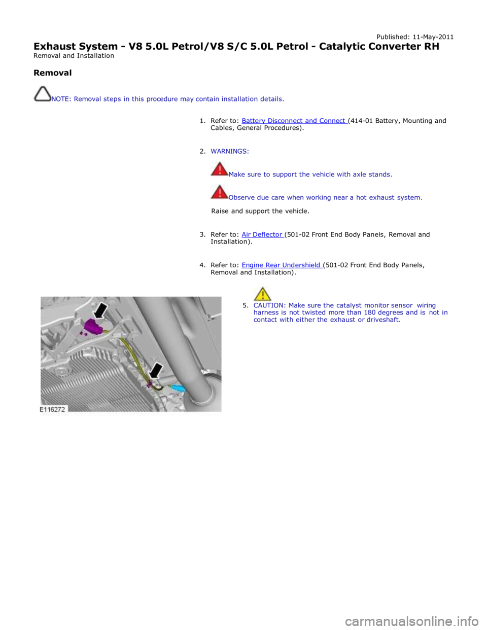
5. CAUTION: Make sure the catalyst monitor sensor wiring
harness is not twisted more than 180 degrees and is not in
contact with either the exhaust or driveshaft.
Page 1555 of 3039

2. NOTE: For NAS vehicles only.
If required, carry out a long drive cycle.
Refer to: Powertrain Control Module (PCM) Long Drive Cycle Self-Test (303-14D Electronic Engine Controls - V8 S/C 5.0L Petrol, General
Procedures).