Engine JAGUAR XFR 2010 1.G Workshop Manual
[x] Cancel search | Manufacturer: JAGUAR, Model Year: 2010, Model line: XFR, Model: JAGUAR XFR 2010 1.GPages: 3039, PDF Size: 58.49 MB
Page 1557 of 3039

Published: 11-May-2011
Exhaust System - V8 5.0L Petrol/V8 S/C 5.0L Petrol - Exhaust System
Removal and Installation
Removal
NOTE: Removal steps in this procedure may contain installation details.
1. Refer to: Battery Disconnect and Connect (414-01 Battery, Mounting and Cables, General Procedures).
2. WARNINGS:
Make sure to support the vehicle with axle stands.
Observe due care when working near a hot exhaust system.
Raise and support the vehicle.
3. Refer to: Air Deflector (501-02 Front End Body Panels, Removal and Installation).
4. Refer to: Engine Rear Undershield (501-02 Front End Body Panels, Removal and Installation).
5.
6. www.JagDocs.com
Page 1561 of 3039

Published: 09-Dec-2012
Exhaust System - V8 5.0L Petrol/V8 S/C 5.0L Petrol - Front Muffler
Removal and Installation
Removal
NOTE: Removal steps in this procedure may contain installation details.
1. WARNINGS:
Make sure to support the vehicle with axle stands.
Observe due care when working near a hot exhaust system.
Raise and support the vehicle.
2. Refer to: Engine Rear Undershield (501-02 Front End Body Panels, Removal and Installation).
3. Torque: 55 Nm 4. Torque: 55 Nm
Page 1565 of 3039

Published: 01-Aug-2012
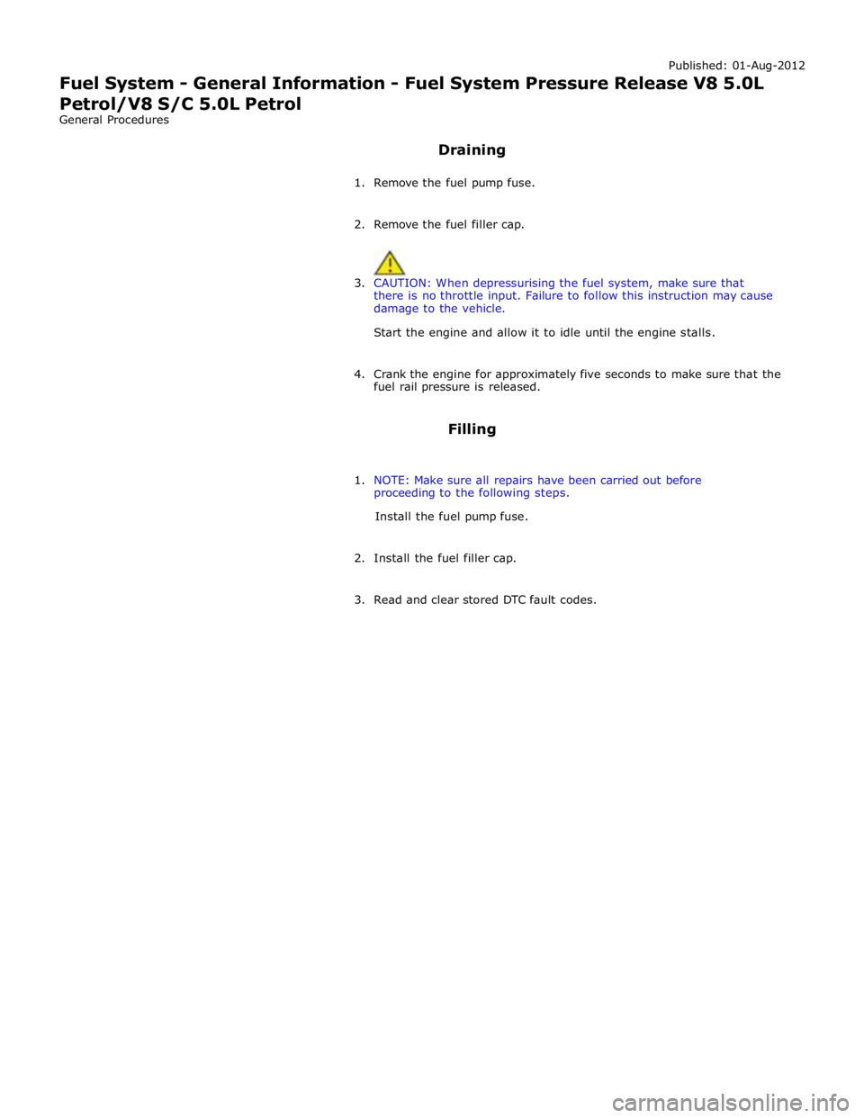
Fuel System - General Information - Fuel System Pressure Release V8 5.0L
Petrol/V8 S/C 5.0L Petrol
General Procedures
Draining
1. Remove the fuel pump fuse.
2. Remove the fuel filler cap.
3. CAUTION: When depressurising the fuel system, make sure that
there is no throttle input. Failure to follow this instruction may cause
damage to the vehicle.
Start the engine and allow it to idle until the engine stalls.
4. Crank the engine for approximately five seconds to make sure that the
fuel rail pressure is released.
Filling
1. NOTE: Make sure all repairs have been carried out before
proceeding to the following steps.
Install the fuel pump fuse.
2. Install the fuel filler cap.
3. Read and clear stored DTC fault codes.
Page 1566 of 3039

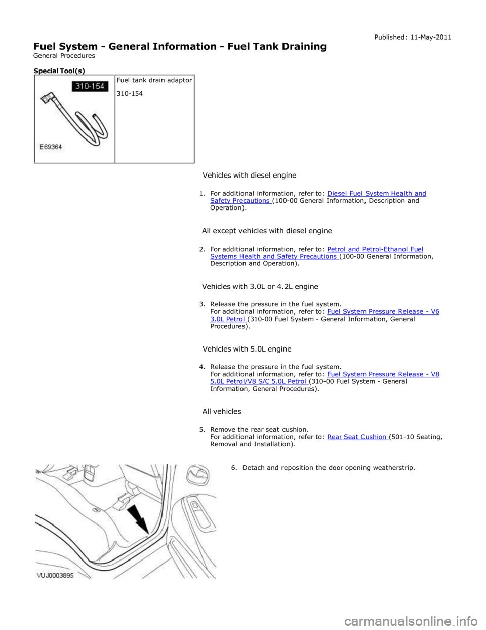
Safety Precautions (100-00 General Information, Description and Operation).
All except vehicles with diesel engine
2. For additional information, refer to: Petrol and Petrol-Ethanol Fuel Systems Health and Safety Precautions (100-00 General Information, Description and Operation).
Vehicles with 3.0L or 4.2L engine
3. Release the pressure in the fuel system.
For additional information, refer to: Fuel System Pressure Release - V6 3.0L Petrol (310-00 Fuel System - General Information, General Procedures).
Vehicles with 5.0L engine
4. Release the pressure in the fuel system.
For additional information, refer to: Fuel System Pressure Release - V8 5.0L Petrol/V8 S/C 5.0L Petrol (310-00 Fuel System - General Information, General Procedures).
All vehicles
5. Remove the rear seat cushion.
For additional information, refer to: Rear Seat Cushion (501-10 Seating, Removal and Installation).
6. Detach and reposition the door opening weatherstrip. Fuel tank drain adaptor
310-154 Special Tool(s)
Page 1568 of 3039

11.
12. CAUTION: The correct measurement must be used to
remove the fuel tank drain port top. Failure to follow this
instruction may result in damage to the vehicle.
NOTE: Vehicles without Diesel engine shown, vehicles
with Diesel engine similar.
Using a suitable tool, remove the top of the fuel tank drain
port.
NOTES:
A fuel vacuum drain unit must be attached to the
special tool to achieve full fuel tank drain.
Vehicles without Diesel engine shown, vehicles with
Diesel engine similar.
Using the special tool, drain the right-hand side of the fuel
tank.
Page 1569 of 3039

13.
14. NOTE: Vehicles without Diesel engine shown, vehicles
with Diesel engine similar.
Remove the special tool.
CAUTION: Make sure the new fuel tank drain port
sealing cap is correctly installed. Failure to follow this
instruction may result in damage to the vehicle.
NOTE: Vehicles without Diesel engine shown, vehicles
with Diesel engine similar.
Install a new fuel tank drain port sealing cap.
Page 1570 of 3039

15.
16. CAUTION: The correct measurement must be used to
remove the fuel tank drain port top. Failure to follow this
instruction may result in damage to the vehicle.
NOTE: Vehicles without Diesel engine shown, vehicles
with Diesel engine similar.
Using a suitable tool, remove the top of the fuel tank drain
port.
NOTES:
A fuel vacuum drain unit must be attached to the
special tool to achieve full fuel tank drain.
Vehicles without Diesel engine shown, vehicles with
Diesel engine similar.
Using the special tool, drain the left-hand side of the fuel
tank.
Page 1571 of 3039

17.
18. NOTE: Vehicles without Diesel engine shown, vehicles
with Diesel engine similar.
Remove the special tool.
CAUTION: Make sure the new fuel tank drain port
sealing cap is correctly installed. Failure to follow this
instruction may result in damage to the vehicle.
NOTE: Vehicles without Diesel engine shown, vehicles
with Diesel engine similar.
Install a new fuel tank drain port sealing cap.
19.
Install the floor aperture cover.
Page 1580 of 3039

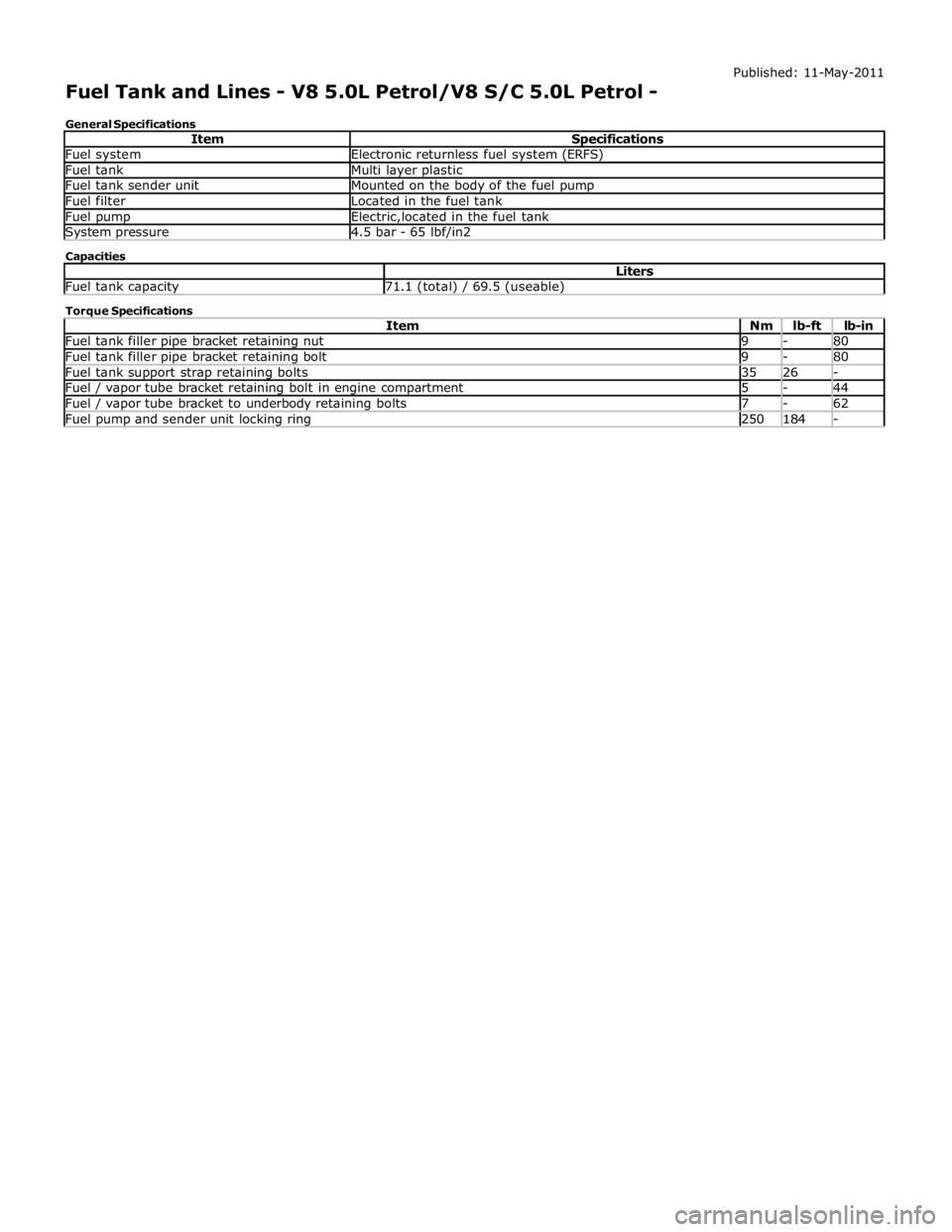
Fuel system Electronic returnless fuel system (ERFS) Fuel tank Multi layer plastic Fuel tank sender unit Mounted on the body of the fuel pump Fuel filter Located in the fuel tank Fuel pump Electric,located in the fuel tank System pressure 4.5 bar - 65 lbf/in2 Capacities Liters Fuel tank capacity 71.1 (total) / 69.5 (useable) Torque Specifications
Item Nm lb-ft lb-in Fuel tank filler pipe bracket retaining nut 9 - 80 Fuel tank filler pipe bracket retaining bolt 9 - 80 Fuel tank support strap retaining bolts 35 26 - Fuel / vapor tube bracket retaining bolt in engine compartment 5 - 44 Fuel / vapor tube bracket to underbody retaining bolts 7 - 62 Fuel pump and sender unit locking ring 250 184 -
Page 1584 of 3039

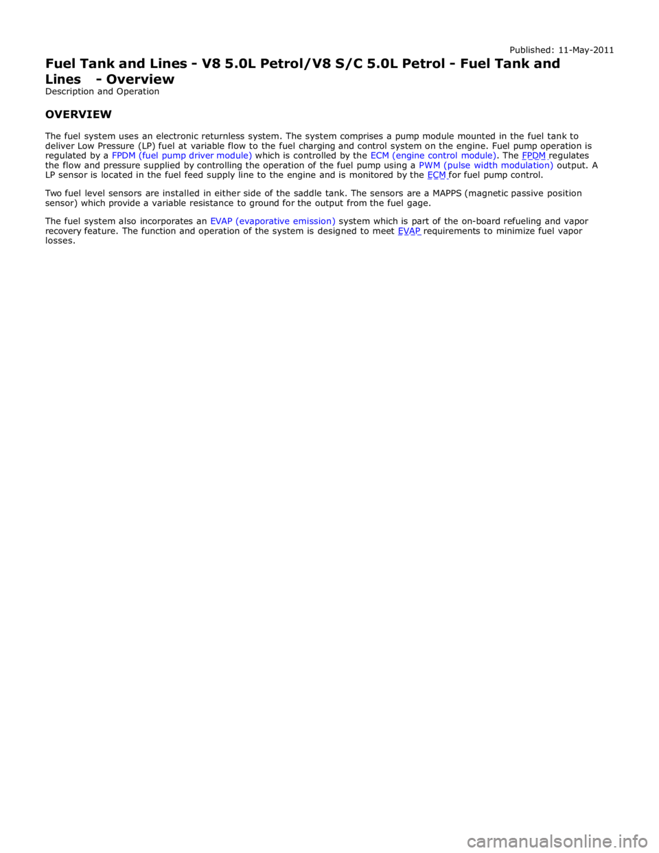
the flow and pressure supplied by controlling the operation of the fuel pump using a PWM (pulse width modulation) output. A
LP sensor is located in the fuel feed supply line to the engine and is monitored by the ECM for fuel pump control.
Two fuel level sensors are installed in either side of the saddle tank. The sensors are a MAPPS (magnetic passive position
sensor) which provide a variable resistance to ground for the output from the fuel gage.
The fuel system also incorporates an EVAP (evaporative emission) system which is part of the on-board refueling and vapor
recovery feature. The function and operation of the system is designed to meet EVAP requirements to minimize fuel vapor losses.