engine JAGUAR XFR 2010 1.G Workshop Manual
[x] Cancel search | Manufacturer: JAGUAR, Model Year: 2010, Model line: XFR, Model: JAGUAR XFR 2010 1.GPages: 3039, PDF Size: 58.49 MB
Page 1711 of 3039

rear window heater switch is pressed or the engine stops.
Automatic operation during a journey is initiated when low ambient air temperatures are experienced and the vehicle has been
travelling for a set period of time above a threshold speed. In this instance, no feedback is given to the driver to inform him
the rear window heater is operational (the switch LED is not illuminated). The duration of heater operation is variable depending on the ambient air temperature, vehicle speed and the amount of time the vehicle has been travelling.
Windshield Heater (Where Fitted)
Windshield heater operation is only enabled when the engine is running. The ATC module controls operation of the windshield heater using two relays in the EJB (engine junction box). When windshield heater operation is required, the ATC module broadcasts a message to the CJB on the medium speed CAN bus. On receipt of the message, the CJB energizes the relays by providing a ground path for both relay coils. This allows a battery feed to flow across the relays to power the windshield left
and right heater elements.
There are two modes of windshield heater operation; manual and automatic.
Manual operation is activated by pressing the windshield heater switch on the integrated control panel. When the switch is
pressed, the status LED in the switch illuminates and the windshield heater elements are energized. Manual operation is discontinued when the windshield heater switch is pressed a second time, 5 minutes have elapsed (the heating phase), or the
engine stops. If manual operation is discontinued by the engine stopping, the previous heating phase is resumed if the engine
is re-started within 30 seconds.
There are two variants of automatic operation; automatic operation at the start of a journey and automatic operation during a
journey.
Automatic operation at the start of a journey is initiated if the ambient air temperature is below 5 °C (41 °F). In this instance,
the switch LED is illuminated and the heater elements are energized for 6.5 minutes. Automatic operation is discontinued if the windshield heater switch is pressed or the engine stops.
Automatic operation during a journey is initiated when low ambient air temperatures are experienced and the vehicle has been
travelling for a set period of time above a threshold speed. In this instance, no feedback is given to the driver to inform him
the windshield heater is operational (the switch LED is not illuminated) and the duration of operation is variable depending upon the ambient air temperature, vehicle speed and the amount of time the vehicle has been travelling.
Exterior Mirror Heaters
Operation of the exterior mirror heaters is fully automatic and not controllable by the driver. Exterior mirror heater operation is
determined by ambient air temperature and windshield wiper status. When ambient air temperature reaches a pre-determined
level, the ATC module broadcasts an exterior mirror heating request to the door modules over the medium speed CAN bus. On receipt of this message, the door modules provide feed and ground connections to both exterior mirror heater elements.
The amount of time the exterior mirror heaters are operational increases if the windshield wipers are switched on. This ensures
the mirrors remain mist free in damp and wet conditions, where there is an increased risk of misting.
Seat Heaters (Where Fitted)
There are four seat heater settings available; off, 1, 2 and 3, which can be selected on the home and climate control screens
of the TSD. The heat setting is relayed to the vehicle occupants through a graduated display on the TSD.
Operation of the heated seats is controlled by the ATC module. When the ATC module receives a heating request from the TSD, it broadcasts a message to the CJB over the medium speed CAN bus. The CJB then provides a hardwired 12 V supply to the three heater elements in the related front seat. The heater elements, two in the seat cushion and one in the seat squab,
are wired in series. The ATC module monitors seat temperature using a temperature sensor located in each seat cushion. The CJB provides the temperature sensors with a 5 V supply. The level of the returned voltage back to the CJB is proportional to the seat temperature. The value of the return signal is broadcast to the ATC module, over the medium speed CAN bus, which allows it to control the seat temperature to the required level. The ATC module will suspend or disable operation of the seat heaters if any of the following occur:
Battery voltage exceeds 16.5 ± 0.3 V for more than 5 seconds. Seat heating is re-enabled when battery voltage
decreases to 16.2 ± 0.3 V.
If a short or open circuit is detected.
If the seat heat temperature rises significantly above the target temperature setting.
The graduated display on the TSD remains illuminated until the seat heaters are turned off or the engine stops. If the engine
is restarted within 30 seconds the seat heater resumes the previous heating level.
Page 1712 of 3039
bus. Temperature control for the heater element is provided by the steering wheel heater control module which receives a
temperature feedback signal from a NTC (negative temperature coefficient) thermistor located within the steering wheel.
ATC Module Component Description
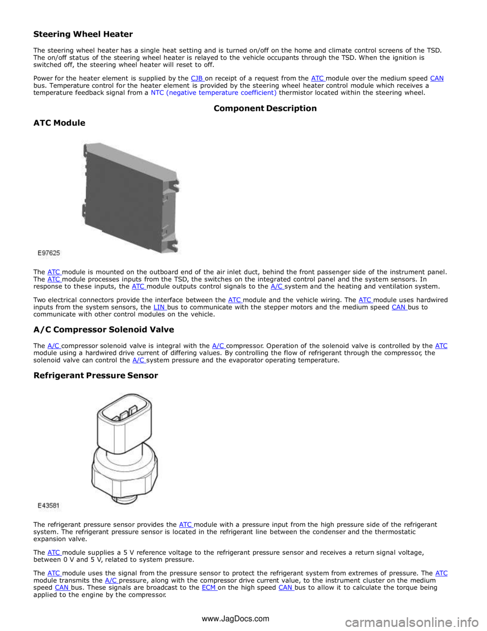
The ATC module is mounted on the outboard end of the air inlet duct, behind the front passenger side of the instrument panel. The ATC module processes inputs from the TSD, the switches on the integrated control panel and the system sensors. In response to these inputs, the ATC module outputs control signals to the A/C system and the heating and ventilation system.
Two electrical connectors provide the interface between the ATC module and the vehicle wiring. The ATC module uses hardwired inputs from the system sensors, the LIN bus to communicate with the stepper motors and the medium speed CAN bus to communicate with other control modules on the vehicle.
A/C Compressor Solenoid Valve
The A/C compressor solenoid valve is integral with the A/C compressor. Operation of the solenoid valve is controlled by the ATC module using a hardwired drive current of differing values. By controlling the flow of refrigerant through the compressor, the
solenoid valve can control the A/C system pressure and the evaporator operating temperature.
Refrigerant Pressure Sensor
The refrigerant pressure sensor provides the ATC module with a pressure input from the high pressure side of the refrigerant system. The refrigerant pressure sensor is located in the refrigerant line between the condenser and the thermostatic
expansion valve.
The ATC module supplies a 5 V reference voltage to the refrigerant pressure sensor and receives a return signal voltage, between 0 V and 5 V, related to system pressure.
The ATC module uses the signal from the pressure sensor to protect the refrigerant system from extremes of pressure. The ATC module transmits the A/C pressure, along with the compressor drive current value, to the instrument cluster on the medium speed CAN bus. These signals are broadcast to the ECM on the high speed CAN bus to allow it to calculate the torque being applied to the engine by the compressor. www.JagDocs.com
Page 1767 of 3039
7 ECT (engine coolant temperature) sensor 8 Ambient temperature sensor 9 Electric booster heater 10 Face/Feet distribution stepper motor 11 RH (right-hand) temperature blend stepper motor 12 LH (left-hand) temperature blend stepper motor 13 Windshield (defrost) distribution stepper motor 14 ATC (automatic temperature control) module 15 150 A megafuse
General System Operation
Operation of the electric booster heater is controlled by the ATC module, which communicates with the micro-controller in the booster heater using the LIN bus. The temperature requested by the ATC module is based on:
The ambient air temperature.
The engine coolant temperature.
The temperatures selected on the integrated control panel.
The blower must be running for the electric booster heater to operate.
If electrical load management is in force, electric booster heater performance is reduced. For additional information, refer to:
Electronic Engine Controls (303-14A, Description and Operation),
Electronic Engine Controls (303-14B Electronic Engine Controls - V6 3.0L Petrol, Description and Operation), Electronic Engine Controls (303-14C, Description and Operation).
Electric Booster Heater Component Description
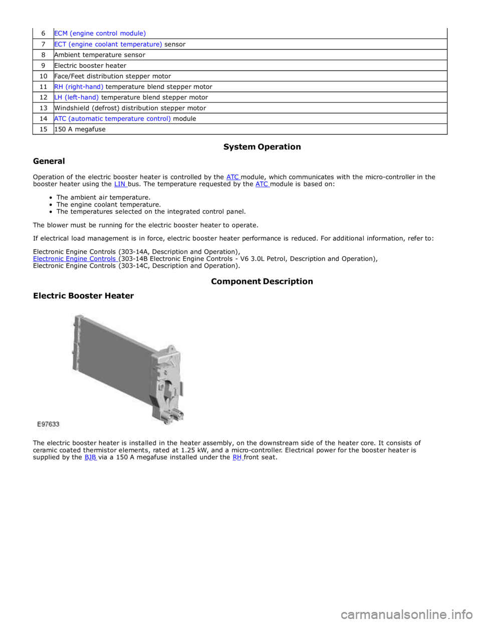
The electric booster heater is installed in the heater assembly, on the downstream side of the heater core. It consists of
ceramic coated thermistor elements, rated at 1.25 kW, and a micro-controller. Electrical power for the booster heater is
supplied by the BJB via a 150 A megafuse installed under the RH front seat.
Page 1770 of 3039
3.
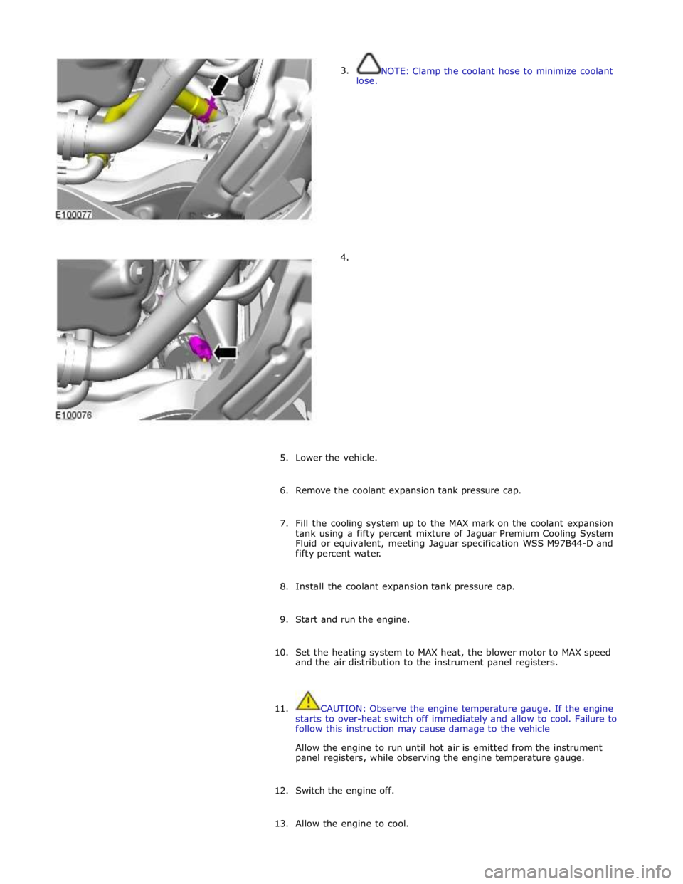
lose.
4. NOTE: Clamp the coolant hose to minimize coolant
5. Lower the vehicle.
6. Remove the coolant expansion tank pressure cap.
7. Fill the cooling system up to the MAX mark on the coolant expansion
tank using a fifty percent mixture of Jaguar Premium Cooling System
Fluid or equivalent, meeting Jaguar specification WSS M97B44-D and
fifty percent water.
8. Install the coolant expansion tank pressure cap.
9. Start and run the engine.
10. Set the heating system to MAX heat, the blower motor to MAX speed
and the air distribution to the instrument panel registers.
11. CAUTION: Observe the engine temperature gauge. If the engine
starts to over-heat switch off immediately and allow to cool. Failure to
follow this instruction may cause damage to the vehicle
Allow the engine to run until hot air is emitted from the instrument
panel registers, while observing the engine temperature gauge.
12. Switch the engine off.
13. Allow the engine to cool.
Page 1771 of 3039

14. WARNINGS:
Never remove the coolant expansion tank cap under any
circumstances while the engine is operating. Failure to follow this
instruction may result in personal injury.
To avoid having scalding hot coolant or steam blowing out of the
cooling system, use extreme care when removing the coolant pressure
cap from a hot cooling system. Wait until the engine has cooled, then
wrap a thick cloth around the coolant pressure cap and turn it slowly
until the pressure begins to release. Step back while the pressure is
released from the system. When certain all the pressure has been
released (still with a cloth) turn and remove the coolant pressure cap
from the coolant expansion tank. Failure to follow these instructions may
result in personal injury.
Release the cooling system pressure.
15. Fill the cooling system up to the MAX mark on the coolant expansion
tank using a fifty percent mixture of Jaguar Premium Cooling System
Fluid or equivalent, meeting Jaguar specification WSS M97B44-D and
fifty percent water.
16. Install the coolant expansion tank pressure cap.
17. Raise the vehicle.
18. Check all coolant hoses for visible signs of coolant leaks.
19. Install the air deflector.
Refer to: Air Deflector (501-02, Removal and Installation).
www.JagDocs.com
Page 1773 of 3039

A/C compressor retaining bolts 25 18 - A/C compressor manifold and tube retaining bolt 9 - 80 A/C condenser core retaining studs 5 - 48 A/C condenser core supply and return lines retaining nuts 8 - 71 Power steering oil cooler retaining nuts 7 - 62 A/C desiccant bag retaining screw (vehicles fitted with petrol engines) 22 16 - A/C desiccant bag retaining screw (vehicles fitted with diesel engines) 4 - 37 A/C pressure cutoff switch 8 - 71
Page 1782 of 3039

Acts as an interface for the passive anti-theft system.
Refer to: Anti-Theft - Active (419-01A Anti-Theft - Active, Description and Operation).
Two analogue gauges are located in the instrument cluster; the speedometer and the tachometer. The speedometer is located
on the LH (left-hand) side of the instrument cluster. The tachometer is located on the RH (right-hand) side of the instrument
cluster
and displays engine speeds up to 7000 Revolutions Per Minute (RPM) for the supercharged engine, 8000 RPM for the naturally
aspirated engines and 6000 RPM for diesel variants.
The message center is a LCD located in a central position in the cluster. The message center displays system status information including fuel quantity remaining. www.JagDocs.com
Page 1783 of 3039
Published: 11-May-2011
Instrument Cluster - Instrument Cluster - System Operation and Component Description
Description and Operation
Control Diagram
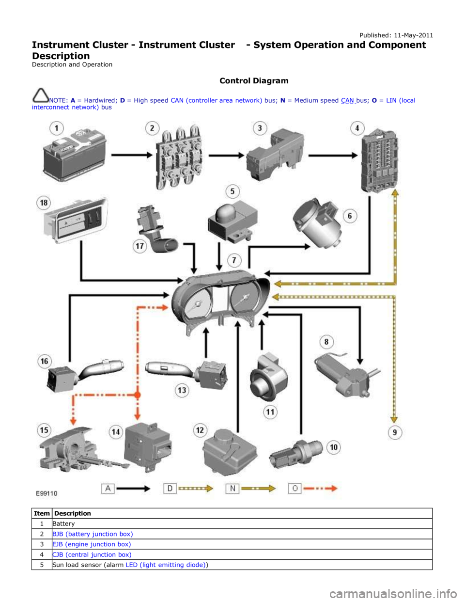
NOTE: A = Hardwired; D = High speed CAN (controller area network) bus; N = Medium speed CAN bus; O = LIN (local interconnect network) bus
Item Description 1 Battery 2 BJB (battery junction box) 3 EJB (engine junction box) 4 CJB (central junction box) 5 Sun load sensor (alarm LED (light emitting diode))
Page 1784 of 3039
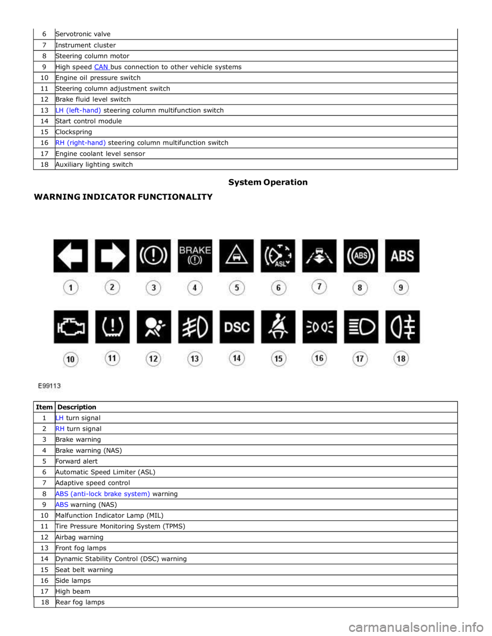
7 Instrument cluster 8 Steering column motor 9 High speed CAN bus connection to other vehicle systems 10 Engine oil pressure switch 11 Steering column adjustment switch 12 Brake fluid level switch 13 LH (left-hand) steering column multifunction switch 14 Start control module 15 Clockspring 16 RH (right-hand) steering column multifunction switch 17 Engine coolant level sensor 18 Auxiliary lighting switch
WARNING INDICATOR FUNCTIONALITY System Operation
Item Description 1 LH turn signal 2 RH turn signal 3 Brake warning 4 Brake warning (NAS) 5 Forward alert 6 Automatic Speed Limiter (ASL) 7 Adaptive speed control 8 ABS (anti-lock brake system) warning 9 ABS warning (NAS) 10 Malfunction Indicator Lamp (MIL) 11 Tire Pressure Monitoring System (TPMS) 12 Airbag warning 13 Front fog lamps 14 Dynamic Stability Control (DSC) warning 15 Seat belt warning 16 Side lamps 17 High beam 18 Rearfoglamps
Page 1785 of 3039
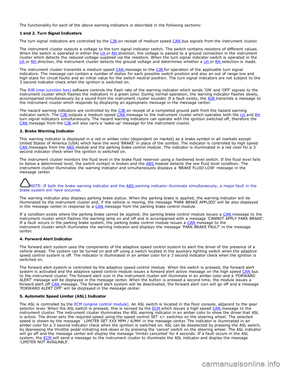
The functionality for each of the above warning indicators is described in the following sections:
1 and 2. Turn Signal Indicators
The turn signal indicators are controlled by the CJB on receipt of medium speed CAN bus signals from the instrument cluster.
The instrument cluster outputs a voltage to the turn signal indicator switch. The switch contains resistors of different values.
When the switch is operated in either the LH or RH direction, the voltage is passed to a ground connection in the instrument cluster which detects the reduced voltage supplied via the resistors. When the turn signal indicator switch is operated in the
LH or RH direction, the instrument cluster detects the ground voltage and determines whether a LH or RH selection is made.
The instrument cluster transmits a medium speed CAN message to the CJB for operation of the applicable turn signal indicators. The message can contain a number of states for each possible switch position and also an out of range low and
high state for circuit faults and an initial value for the switch neutral position. The turn signal indicators are not subject to the
3 second indicator check when the ignition is switched on.
The RJB (rear junction box) software controls the flash rate of the warning indicator which sends 'ON' and 'OFF' signals to the
instrument cluster which flashes the indicators in a green color. During normal operation, the warning indicator flashes slowly,
accompanied simultaneously by a sound from the instrument cluster sounder. If a fault exists, the RJB transmits a message to the instrument cluster which responds by displaying an appropriate message in the message center.
The hazard warning indicators are controlled by the CJB on receipt of a completed ground path from the hazard warning indicator switch. The CJB outputs a medium speed CAN message to the instrument cluster which operates both the LH and RH turn signal indicators simultaneously. The hazard warning indicators can operate with the ignition switched off, therefore the
CAN message from the CJB will also carry a 'wake-up' message for the instrument cluster. 3. Brake Warning Indicator
This warning indicator is displayed in a red or amber color (dependant on market) as a brake symbol in all markets except
United States of America (USA) which have the word 'BRAKE' in place of the symbol. The indicator is controlled by high speed
CAN messages from the ABS module and the parking brake control module. The indicator is illuminated in a red color for a 3 second indicator check when the ignition is switched on.
The instrument cluster monitors the fluid level in the brake fluid reservoir using a hardwired level switch. If the fluid level falls
to below a determined level, the switch contact is broken and the ABS module detects the low fluid level condition. The instrument cluster illuminates the warning indicator and simultaneously displays a 'BRAKE FLUID LOW' message in the
message center.
NOTE: If both the brake warning indicator and the ABS warning indicator illuminate simultaneously, a major fault in the brake system will have occurred.
The warning indicator also displays parking brake status. When the parking brake is applied, the warning indicator will be
illuminated by the instrument cluster and, if the vehicle is moving, the message 'PARK BRAKE APPLIED' will be also displayed
in the message center in response to a CAN message from the parking brake control module.
If a condition exists where the parking brake cannot be applied, the parking brake control module issues a CAN message to the instrument cluster which flashes the warning lamp on and off and is accompanied with a message 'CANNOT APPLY PARK BRAKE'.
If a fault occurs in the parking brake system, the parking brake control module issues a CAN message to the instrument cluster which illuminates the warning indicator and displays the message 'PARK BRAKE FAULT' in the message
center.
4. Forward Alert Indicator
The forward alert system uses the components of the adaptive speed control system to alert the driver of the presence of a
vehicle ahead. The system can be turned on and off using a switch located in the auxiliary lighting switch when the adaptive
speed control system is off. The indicator is illuminated in an amber color for a 3 second indicator check when the ignition is
switched on.
The forward alert system is controlled by the adaptive speed control module. When the switch is pressed, the forward alert
system is activated and the adaptive speed control module issues a forward alert active message on the high speed CAN bus to the instrument cluster. The forward alert icon in the instrument cluster will illuminate in an amber color and a 'FORWARD
ALERT' message will be displayed in the message center. When the button is pressed a second time, the module issues a
forward alert off CAN message. The forward alert system will be deactivated, the forward alert icon will go off and a message 'FORWARD ALERT OFF' will be displayed in the message center.
5. Automatic Speed Limiter (ASL) Indicator
The ASL is controlled by the ECM (engine control module). An ASL switch is located in the floor console, adjacent to the gear
selector lever. When the ASL switch is pressed, this is sensed by the ECM which issues a high speed CAN message to the instrument cluster. The instrument cluster illuminates the ASL warning indicator in an amber color to show the driver that ASL
is active. The driver sets the required speed using the speed control SET +/- switches on the steering wheel. The selected
speed is shown by the message ' LIMITER SET XXX MPH / K/MH' in the message center. The indicator is illuminated in an
amber color for a 3 second indicator check when the ignition is switched on. ASL can be deselected by pressing the ASL switch,
by depressing the throttle pedal initiating kick-down or by pressing the 'cancel' switch on the steering wheel. The ASL indicator
will go off and the message center will display the message 'limiter cancelled' for 4 seconds. If a fault occurs in the ASL
system, the ECM will send a message to the instrument cluster to illuminate the ASL indicator and display the message 'LIMITER NOT AVAILABLE'.