srs JAGUAR XFR 2010 1.G Service Manual
[x] Cancel search | Manufacturer: JAGUAR, Model Year: 2010, Model line: XFR, Model: JAGUAR XFR 2010 1.GPages: 3039, PDF Size: 58.49 MB
Page 2634 of 3039

Supplemental Restraint System - C-Pillar Side Impact Sensor
Removal and Installation
Removal
NOTE: Removal steps in this procedure may contain installation details. Published: 11-May-2011
1. Make the air bag supplemental restraint system (SRS) safe.
Refer to: Standard Workshop Practices (100-00 General Information, Description and Operation).
2. WARNING: To avoid accidental deployment and possible personal injury,
the backup power supply must be depleted before repairing or replacing
any air bag supplementary restraints system (SRS) components. To
deplete the backup power supply energy, disconnect the battery ground
cable and wait for one minute. Failure to follow this instruction may
result in personal injury.
Refer to: Battery Disconnect and Connect (414-01 Battery, Mounting and Cables, General Procedures).
3. Refer to: Rear Seat Bolster (501-10 Seating, Removal and Installation).
Installation
4. Torque: 12 Nm
1. To install, reverse the removal procedure.
2. If a new component has been installed, configure using Jaguar approved
diagnostic equipment. www.JagDocs.com
Page 2635 of 3039

Supplemental Restraint System - Crash Sensor
Removal and Installation
Removal
NOTE: Removal steps in this procedure may contain installation details. Published: 11-May-2011
1. Make the air bag supplemental restraint system (SRS) safe.
Refer to: Standard Workshop Practices (100-00 General Information, Description and Operation).
2. WARNING: To avoid accidental deployment and possible personal injury,
the backup power supply must be depleted before repairing or replacing
any air bag supplementary restraints system (SRS) components. To
deplete the backup power supply energy, disconnect the battery ground
cable and wait for one minute. Failure to follow this instruction may
result in personal injury.
Refer to: Battery Disconnect and Connect (414-01 Battery, Mounting and Cables, General Procedures).
Installation
3. Torque: 10 Nm
1. Install is the reverse of removal.
2. If a new component has been installed, configure using Jaguar approved
diagnostic equipment.
Page 2636 of 3039
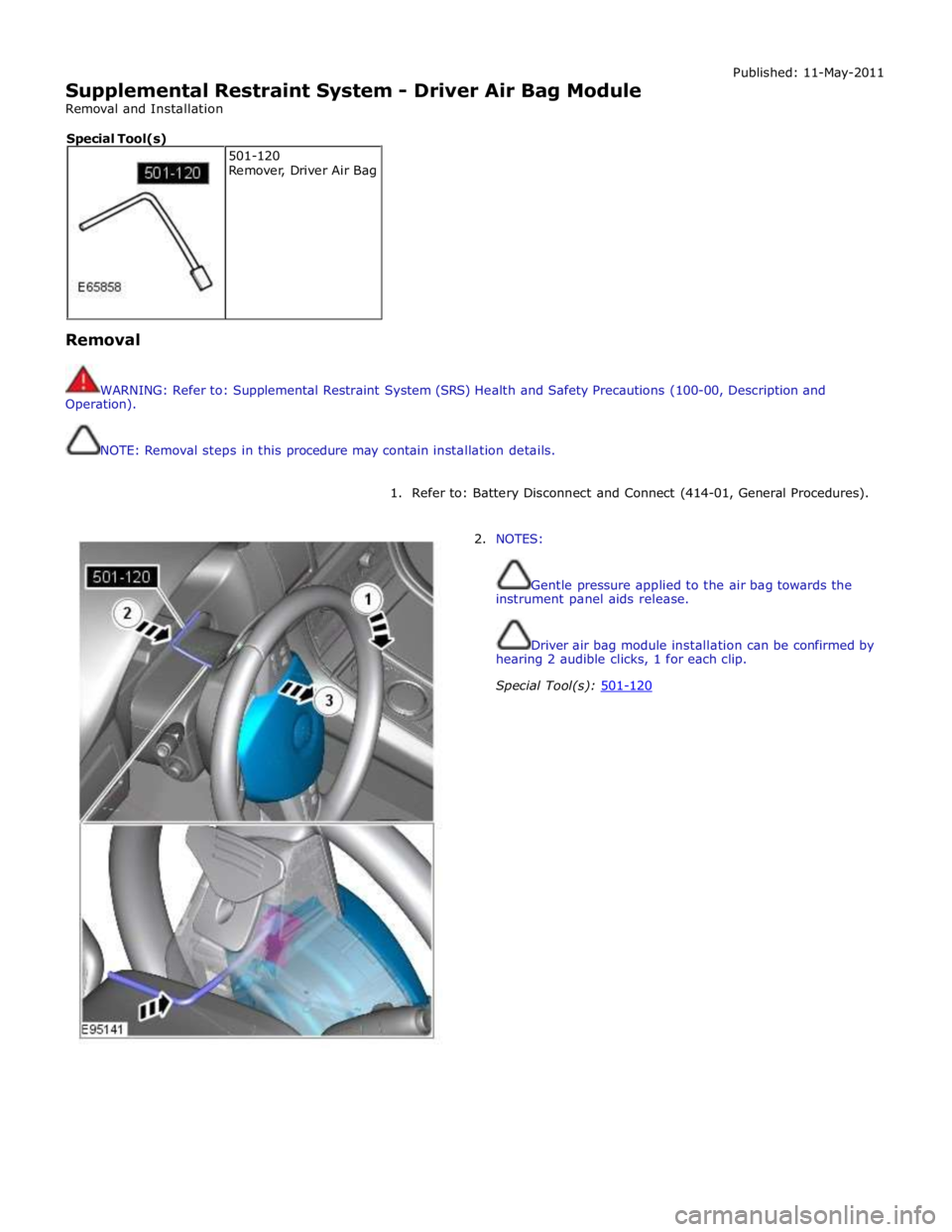
Supplemental Restraint System - Driver Air Bag Module
Removal and Installation Published: 11-May-2011
Removal
WARNING: Refer to: Supplemental Restraint System (SRS) Health and Safety Precautions (100-00, Description and
Operation).
NOTE: Removal steps in this procedure may contain installation details.
1. Refer to: Battery Disconnect and Connect (414-01, General Procedures).
2. NOTES:
Gentle pressure applied to the air bag towards the
instrument panel aids release.
Driver air bag module installation can be confirmed by
hearing 2 audible clicks, 1 for each clip.
Special Tool(s): 501-120 501-120
Remover, Driver Air Bag Special Tool(s)
Page 2638 of 3039
Published: 11-May-2011
Supplemental Restraint System - Occupant Classification Sensor
Removal and Installation
Removal
WARNINGS:
To avoid accidental deployment, the restraints control module backup power supply must be depleted. Wait at least one
minute after disconnecting the battery ground cable(s) before commencing any repair or adjustment to the supplemental
restraint system (SRS), or any component(s) adjacent to the SRS sensors. Failure to follow these instructions may result in
personal injury.
Always wear safety glasses when working on an air bag equipped vehicle and when handling an air bag module. Failure to
follow this instruction may result in personal injury.
To minimize the possibility of premature deployment, do not use radio key code savers when working on the
supplemental restraint system. Failure to follow this instruction may result in personal injury.
To minimize the possibility of injury in the event of premature deployment, always carry a live air bag module with the
bag and trim cover pointed away from the body. Failure to follow this instruction may result in personal injury.
To minimize the possibility of premature deployment, live air bag modules must only be placed on work benches which
have been ground bonded and with the trim cover facing up. Failure to follow these instructions may result in personal injury.
Never probe the electrical connectors of air bag modules or any other supplemental restraint system component. Failure
to follow this instruction may result in personal injury.
Painting over the driver air bag module trim cover or instrument panel could lead to deterioration of the trim cover and air
bags. Do not for any reason attempt to paint discoloured or damaged air bag module trim covers or instrument panel. Install a
new component. Failure to follow this instruction may result in personal injury.
CAUTIONS:
The front passenger seat occupant classification sensor is available only as a service kit. No attempt should be made to
replace individual components. Failure to follow this instruction may result in personal injury.
Check for correct operation of the front seat after completion of the procedure to make sure that the wiring harness has
not become trapped or stretched.
NOTES:
Note the routing of the seat harness.
Some variation in the illustrations may occur, but the essential information is always correct.
1. Make the air bag supplemental restraint system (SRS) safe.
Refer to: Standard Workshop Practices (100-00 General Information, Description and Operation).
2. Refer to: Battery Disconnect and Connect (414-01 Battery, Mounting and Cables, General Procedures).
3. Refer to: Front Seat Backrest Cover (501-10 Seating, Removal and Installation).
Page 2644 of 3039
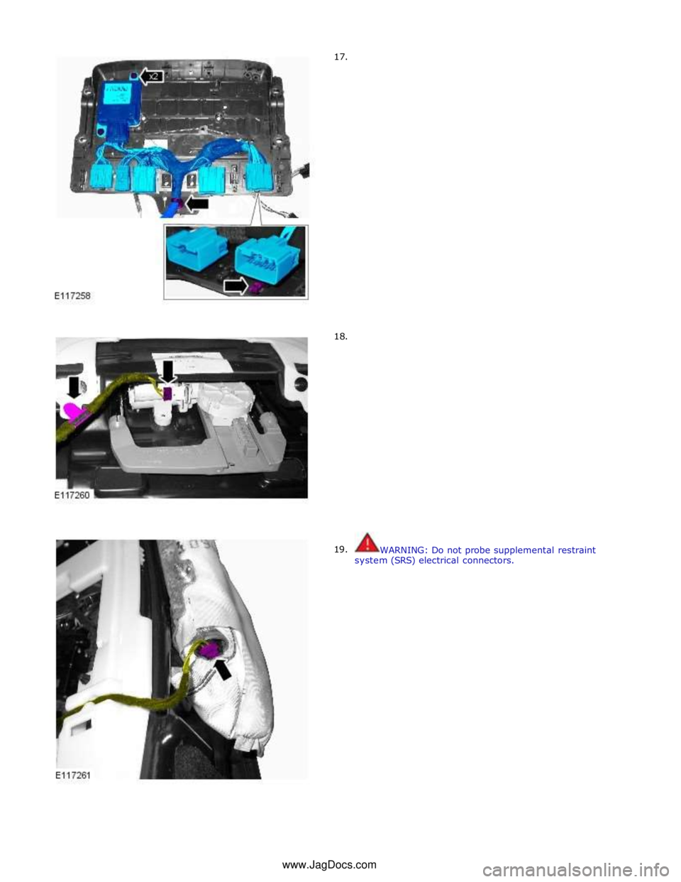
17.
18.
19.
WARNING: Do not probe supplemental restraint
system (SRS) electrical connectors. www.JagDocs.com
Page 2652 of 3039
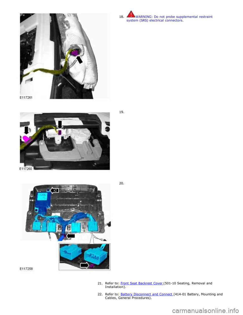
18.
19.
20. WARNING: Do not probe supplemental restraint
system (SRS) electrical connectors.
21.
Refer to: Front Seat Backrest Cover (501-10 Seating, Removal and Installation).
22. Refer to: Battery Disconnect and Connect (414-01 Battery, Mounting and Cables, General Procedures).
Page 2665 of 3039

Published: 11-May-2011
Supplemental Restraint System - Restraints Control Module (RCM)
Removal and Installation
Removal
NOTE: Removal steps in this procedure may contain installation details.
1. Make the air bag supplemental restraint system (SRS) safe.
Refer to: Standard Workshop Practices (100-00 General Information, Description and Operation).
2. WARNING: To avoid accidental deployment and possible personal injury,
the backup power supply must be depleted before repairing or replacing
any air bag supplementary restraints system (SRS) components. To
deplete the backup power supply energy, disconnect the battery ground
cable and wait for one minute. Failure to follow this instruction may
result in personal injury.
Refer to: Battery Disconnect and Connect (414-01 Battery, Mounting and Cables, General Procedures).
3.
4.
Page 2666 of 3039
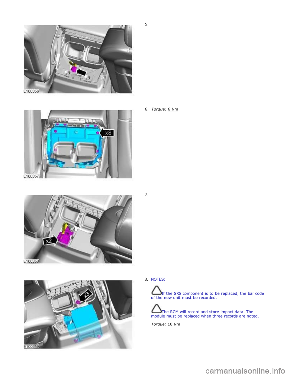
5.
6. Torque: 6 Nm 7.
8. NOTES:
If the SRS component is to be replaced, the bar code
of the new unit must be recorded.
The RCM will record and store impact data. The
module must be replaced when three records are noted.
Torque: 10 Nm
Page 2668 of 3039

Supplemental Restraint System - Side Air Bag Module
Removal and Installation
Removal
NOTE: Removal steps in this procedure may contain installation details. Published: 07-Sep-2011
1. Make the air bag supplemental restraint system (SRS) safe.
For additional information, refer to: Standard Workshop Practices (100-00 General Information, Description and Operation).
2. Disconnect the battery ground cable.
For additional information, refer to: Battery Disconnect and Connect (414-01 Battery, Mounting and Cables, General Procedures).
3. Remove the front seat.
For additional information, refer to: Front Seat (501-10 Seating, Removal and Installation).
4. Remove the front seat backrest lower rear cover.
Page 2673 of 3039

Supplemental Restraint System - Side Air Curtain Module
Removal and Installation
Removal
NOTE: Removal steps in this procedure may contain installation details.
All vehicles Published: 19-May-2011
1. Make the air bag supplemental restraint system (SRS) safe.
Refer to: Standard Workshop Practices (100-00 General Information, Description and Operation).
2. Refer to: Battery Disconnect and Connect (414-01 Battery, Mounting and Cables, General Procedures).
3. Refer to: Interior Rear View Mirror (501-09 Rear View Mirrors, Removal and Installation).
4. Refer to: Overhead Console (501-12 Instrument Panel and Console, Removal and Installation).
5. Refer to: Sun Visor (501-05 Interior Trim and Ornamentation, Removal and Installation).
6. Refer to: A-Pillar Trim Panel (501-05 Interior Trim and Ornamentation, Removal and Installation).
7. Refer to: B-Pillar Upper Trim Panel (501-05 Interior Trim and Ornamentation, Removal and Installation).
8. Refer to: C-Pillar Lower Trim Panel (501-05 Interior Trim and Ornamentation, Removal and Installation).
9. Torque: 2 Nm