Engine JAGUAR XFR 2010 1.G Workshop Manual
[x] Cancel search | Manufacturer: JAGUAR, Model Year: 2010, Model line: XFR, Model: JAGUAR XFR 2010 1.GPages: 3039, PDF Size: 58.49 MB
Page 1821 of 3039
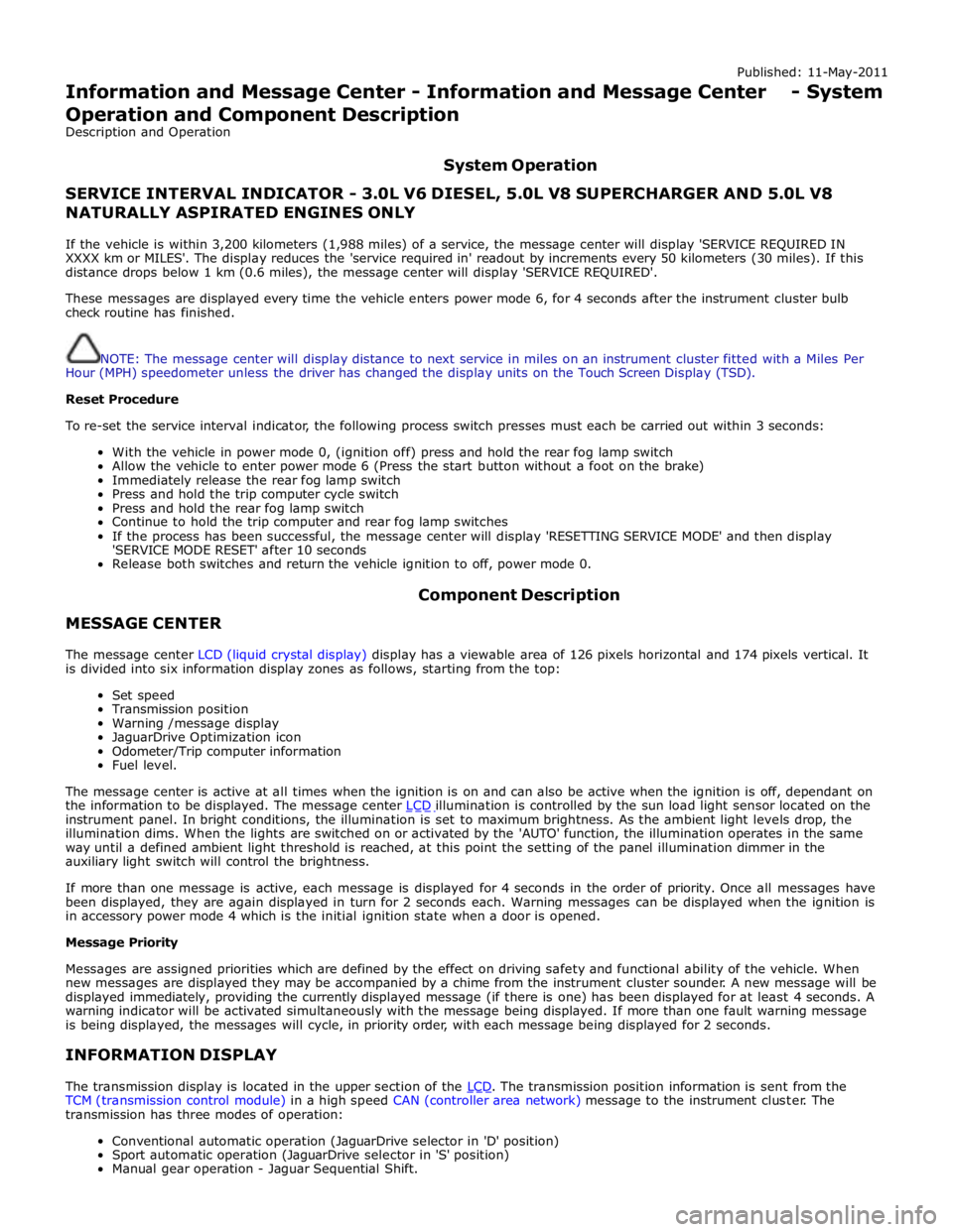
Published: 11-May-2011
Information and Message Center - Information and Message Center - System
Operation and Component Description
Description and Operation
System Operation
SERVICE INTERVAL INDICATOR - 3.0L V6 DIESEL, 5.0L V8 SUPERCHARGER AND 5.0L V8 NATURALLY ASPIRATED ENGINES ONLY
If the vehicle is within 3,200 kilometers (1,988 miles) of a service, the message center will display 'SERVICE REQUIRED IN
XXXX km or MILES'. The display reduces the 'service required in' readout by increments every 50 kilometers (30 miles). If this
distance drops below 1 km (0.6 miles), the message center will display 'SERVICE REQUIRED'.
These messages are displayed every time the vehicle enters power mode 6, for 4 seconds after the instrument cluster bulb
check routine has finished.
NOTE: The message center will display distance to next service in miles on an instrument cluster fitted with a Miles Per
Hour (MPH) speedometer unless the driver has changed the display units on the Touch Screen Display (TSD).
Reset Procedure
To re-set the service interval indicator, the following process switch presses must each be carried out within 3 seconds:
With the vehicle in power mode 0, (ignition off) press and hold the rear fog lamp switch
Allow the vehicle to enter power mode 6 (Press the start button without a foot on the brake)
Immediately release the rear fog lamp switch
Press and hold the trip computer cycle switch
Press and hold the rear fog lamp switch
Continue to hold the trip computer and rear fog lamp switches
If the process has been successful, the message center will display 'RESETTING SERVICE MODE' and then display
'SERVICE MODE RESET' after 10 seconds
Release both switches and return the vehicle ignition to off, power mode 0.
MESSAGE CENTER Component Description
The message center LCD (liquid crystal display) display has a viewable area of 126 pixels horizontal and 174 pixels vertical. It
is divided into six information display zones as follows, starting from the top:
Set speed
Transmission position
Warning /message display
JaguarDrive Optimization icon
Odometer/Trip computer information
Fuel level.
The message center is active at all times when the ignition is on and can also be active when the ignition is off, dependant on
the information to be displayed. The message center LCD illumination is controlled by the sun load light sensor located on the instrument panel. In bright conditions, the illumination is set to maximum brightness. As the ambient light levels drop, the
illumination dims. When the lights are switched on or activated by the 'AUTO' function, the illumination operates in the same
way until a defined ambient light threshold is reached, at this point the setting of the panel illumination dimmer in the
auxiliary light switch will control the brightness.
If more than one message is active, each message is displayed for 4 seconds in the order of priority. Once all messages have
been displayed, they are again displayed in turn for 2 seconds each. Warning messages can be displayed when the ignition is
in accessory power mode 4 which is the initial ignition state when a door is opened.
Message Priority
Messages are assigned priorities which are defined by the effect on driving safety and functional ability of the vehicle. When
new messages are displayed they may be accompanied by a chime from the instrument cluster sounder. A new message will be
displayed immediately, providing the currently displayed message (if there is one) has been displayed for at least 4 seconds. A
warning indicator will be activated simultaneously with the message being displayed. If more than one fault warning message
is being displayed, the messages will cycle, in priority order, with each message being displayed for 2 seconds.
INFORMATION DISPLAY
The transmission display is located in the upper section of the LCD. The transmission position information is sent from the TCM (transmission control module) in a high speed CAN (controller area network) message to the instrument cluster. The
transmission has three modes of operation:
Conventional automatic operation (JaguarDrive selector in 'D' position)
Sport automatic operation (JaguarDrive selector in 'S' position)
Manual gear operation - Jaguar Sequential Shift.
Page 1822 of 3039
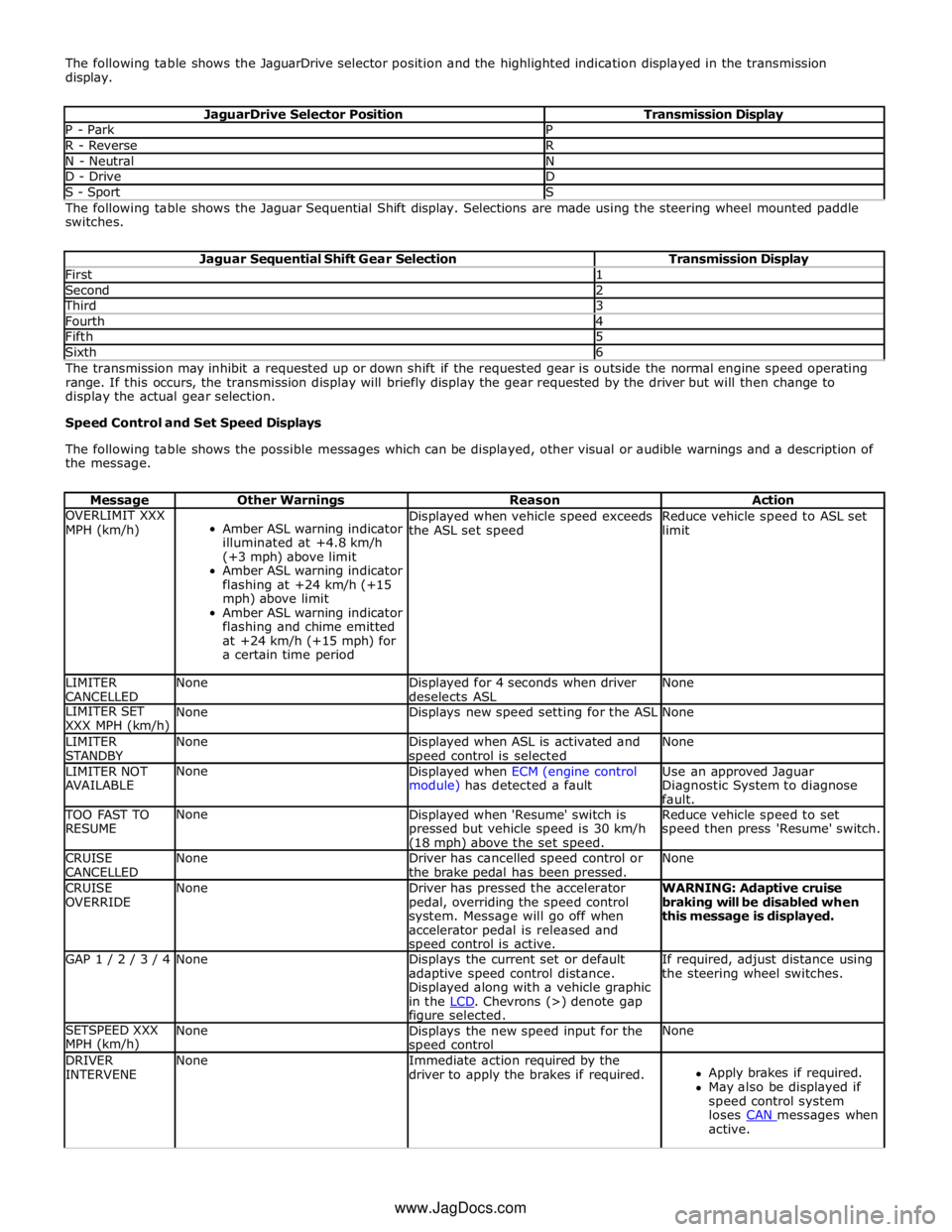
The following table shows the JaguarDrive selector position and the highlighted indication displayed in the transmission
display.
JaguarDrive Selector Position Transmission Display P - Park P R - Reverse R N - Neutral N D - Drive D S - Sport S The following table shows the Jaguar Sequential Shift display. Selections are made using the steering wheel mounted paddle
switches.
Jaguar Sequential Shift Gear Selection Transmission Display First 1 Second 2 Third 3 Fourth 4 Fifth 5 Sixth 6 The transmission may inhibit a requested up or down shift if the requested gear is outside the normal engine speed operating
range. If this occurs, the transmission display will briefly display the gear requested by the driver but will then change to
display the actual gear selection.
Speed Control and Set Speed Displays
The following table shows the possible messages which can be displayed, other visual or audible warnings and a description of
the message.
Message Other Warnings Reason Action OVERLIMIT XXX
MPH (km/h)
Amber ASL warning indicator
illuminated at +4.8 km/h
(+3 mph) above limit
Amber ASL warning indicator
flashing at +24 km/h (+15
mph) above limit
Amber ASL warning indicator
flashing and chime emitted
at +24 km/h (+15 mph) for
a certain time period Displayed when vehicle speed exceeds
the ASL set speed Reduce vehicle speed to ASL set
limit LIMITER
CANCELLED None
Displayed for 4 seconds when driver
deselects ASL None LIMITER SET
XXX MPH (km/h) None Displays new speed setting for the ASL None LIMITER
STANDBY None
Displayed when ASL is activated and speed control is selected None LIMITER NOT
AVAILABLE None
Displayed when ECM (engine control
module) has detected a fault Use an approved Jaguar
Diagnostic System to diagnose
fault. TOO FAST TO
RESUME None
Displayed when 'Resume' switch is
pressed but vehicle speed is 30 km/h (18 mph) above the set speed. Reduce vehicle speed to set
speed then press 'Resume' switch. CRUISE
CANCELLED None
Driver has cancelled speed control or
the brake pedal has been pressed. None CRUISE
OVERRIDE None
Driver has pressed the accelerator
pedal, overriding the speed control
system. Message will go off when
accelerator pedal is released and speed control is active. WARNING: Adaptive cruise
braking will be disabled when
this message is displayed. GAP 1 / 2 / 3 / 4 None
Displays the current set or default
adaptive speed control distance.
Displayed along with a vehicle graphic
in the LCD. Chevrons (>) denote gap figure selected. If required, adjust distance using
the steering wheel switches. SETSPEED XXX
MPH (km/h) None
Displays the new speed input for the speed control None DRIVER
INTERVENE None
Immediate action required by the
driver to apply the brakes if required.
Apply brakes if required.
May also be displayed if
speed control system
loses CAN messages when active. www.JagDocs.com
Page 1825 of 3039
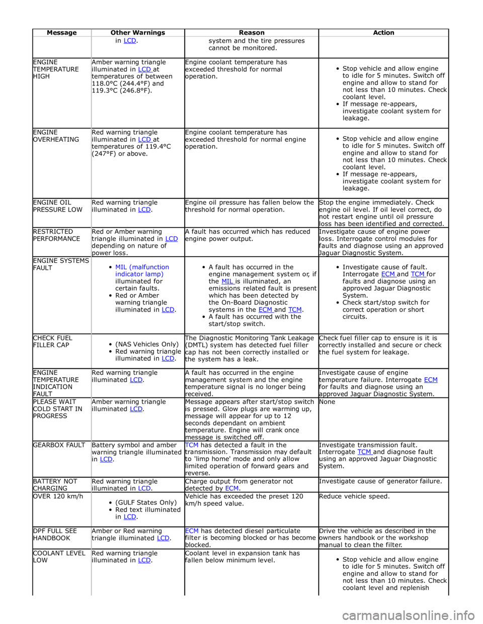
Message Other Warnings Reason Action in LCD. system and the tire pressures
cannot be monitored. ENGINE TEMPERATURE
HIGH Amber warning triangle
illuminated in LCD at temperatures of between
118.0°C (244.4°F) and
119.3°C (246.8°F). Engine coolant temperature has
exceeded threshold for normal
operation.
Stop vehicle and allow engine
to idle for 5 minutes. Switch off
engine and allow to stand for
not less than 10 minutes. Check
coolant level.
If message re-appears,
investigate coolant system for
leakage. ENGINE
OVERHEATING Red warning triangle
illuminated in LCD at temperatures of 119.4°C
(247°F) or above. Engine coolant temperature has
exceeded threshold for normal engine
operation.
Stop vehicle and allow engine
to idle for 5 minutes. Switch off
engine and allow to stand for
not less than 10 minutes. Check
coolant level.
If message re-appears,
investigate coolant system for
leakage. ENGINE OIL
PRESSURE LOW Red warning triangle
illuminated in LCD. Engine oil pressure has fallen below the
threshold for normal operation. Stop the engine immediately. Check
engine oil level. If oil level correct, do
not restart engine until oil pressure
loss has been identified and corrected. RESTRICTED
PERFORMANCE Red or Amber warning
triangle illuminated in LCD depending on nature of power loss. A fault has occurred which has reduced
engine power output. Investigate cause of engine power
loss. Interrogate control modules for
faults and diagnose using an approved Jaguar Diagnostic System. ENGINE SYSTEMS
FAULT
MIL (malfunction
indicator lamp)
illuminated for
certain faults.
Red or Amber
warning triangle
illuminated in LCD.
A fault has occurred in the
engine management system or, if
the MIL is illuminated, an emissions related fault is present
which has been detected by
the On-Board Diagnostic
systems in the ECM and TCM. A fault has occurred with the
start/stop switch.
Investigate cause of fault.
Interrogate ECM and TCM for faults and diagnose using an
approved Jaguar Diagnostic
System.
Check start/stop switch for
correct operation or short
circuits. CHECK FUEL
FILLER CAP
(NAS Vehicles Only)
Red warning triangle
illuminated in LCD. The Diagnostic Monitoring Tank Leakage
(DMTL) system has detected fuel filler
cap has not been correctly installed or
the system has a leak. Check fuel filler cap to ensure is it is
correctly installed and secure or check
the fuel system for leakage. ENGINE TEMPERATURE
INDICATION
FAULT Red warning triangle
illuminated LCD. A fault has occurred in the engine
management system and the engine
temperature signal is no longer being
received. Investigate cause of engine
temperature failure. Interrogate ECM for faults and diagnose using an approved Jaguar Diagnostic System. PLEASE WAIT
COLD START IN
PROGRESS Amber warning triangle
illuminated LCD. Message appears after start/stop switch
is pressed. Glow plugs are warming up,
message will appear for up to 12
seconds dependant on ambient
temperature. Engine will crank once message is switched off. None GEARBOX FAULT
Battery symbol and amber
warning triangle illuminated
in LCD. TCM has detected a fault in the Investigate transmission fault. transmission. Transmission may default
to 'limp home' mode and only allow
limited operation of forward gears and
reverse. Interrogate TCM and diagnose fault using an approved Jaguar Diagnostic
System. BATTERY NOT
CHARGING Red warning triangle
illuminated in LCD. Charge output from generator not
detected by ECM. Investigate cause of generator failure. OVER 120 km/h
(GULF States Only)
Red text illuminated
in LCD. Vehicle has exceeded the preset 120
km/h speed value. Reduce vehicle speed. DPF FULL SEE
HANDBOOK Amber or Red warning
triangle illuminated LCD. ECM has detected diesel particulate Drive the vehicle as described in the filter is becoming blocked or has become
blocked. owners handbook or the workshop
manual to clean the filter. COOLANT LEVEL
LOW Red warning triangle
illuminated in LCD. Coolant level in expansion tank has
fallen below minimum level.
Stop vehicle and allow engine
to idle for 5 minutes. Switch off
engine and allow to stand for
not less than 10 minutes. Check
coolant level and replenish
Page 1827 of 3039
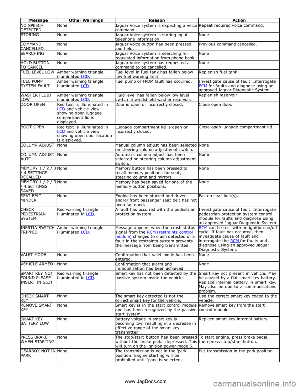
NO SPEECH
DETECTED None
Jaguar Voice system is expecting a voice
command . Repeat required voice command. STORING None
Jaguar Voice system is storing input telephone information. None COMMAND
CANCELLED None
Jaguar Voice button has been pressed
and held. Previous command cancelled. SEARCHING None
Jaguar Voice system is searching for requested information from phone book. None HOLD BUTTON TO CANCEL None
Jaguar Voice system has requested a
command to be cancelled. None FUEL LEVEL LOW
Amber warning triangle
illuminated LCD. Fuel level in fuel tank has fallen below
low fuel warning limit. Replenish fuel tank. FUEL PUMP
SYSTEM FAULT Amber warning triangle
illuminated LCD. Fuel pump or FPDM fault has occurred.
Investigate cause of fault. Interrogate
ECM for faults and diagnose using an approved Jaguar Diagnostic System. WASHER FLUID
LOW Amber warning triangle
illuminated LCD. Fluid level has fallen below low level
switch in windshield washer reservoir. Replenish reservoir. DOOR OPEN
Red text is illuminated in
LCD and vehicle view Door is open or incorrectly closed. Close open door. showing open luggage
compartment lid is
displayed. BOOT OPEN
Red text is illuminated in
LCD and vehicle view Luggage compartment lid is open or incorrectly closed. Close open luggage compartment lid. showing open door location
is displayed. COLUMN ADJUST None
Manual column adjust has been selected
on steering column adjustment switch. None COLUMN ADJUST
AUTO None
Automatic column adjust has been
selected on steering column adjustment
switch. None MEMORY 1 / 2 / 3 / 4 SETTINGS
RECALLED None
Memory button has been pressed to
recall memory positions for seat, steering column and mirrors. None MEMORY 1 / 2 / 3 / 4 SETTINGS
SAVED None
Memory has been saved for one of the
memory button positions. None SEAT BELT
MINDER None
Engine has been started and driver
and/or front passenger seat belt has not
been fastened. Fasten seat belt(s). CHECK
PEDESTRIAN
SYSTEM Red warning triangle
illuminated in LCD. A fault has occurred with the pedestrian
protection system. Investigate cause of fault. Interrogate
pedestrian protection system control
module for faults and diagnose using
an approved Jaguar Diagnostic System. INERTIA SWITCH TRIPPED Amber warning triangle
illuminated LCD. Message appears when the crash status
signal from the RCM (restraints control
module) changes to crash detected or a
fault in the restraints system prevents
the message from being transmitted. RCM can be rest with an ignition on/off cycle. If fault has occurred, then
investigate cause of fault and
interrogate the RCM for faults and diagnose using an approved Jaguar
Diagnostic System. VALET MODE None
Confirmation that valet mode has been
entered. None VEHICLE ARMED None
Confirmation that alarm and
immobilization has been achieved. None SMART KEY NOT
FOUND PLEASE
INSERT IN SLOT Red warning triangle
illuminated in LCD. Smart key has not been detected by the
passive system inside the vehicle. Smart key not present in vehicle. May
be caused by a flat smart key battery.
Replace internal battery in smart key.
May also be due to a communications problem. CHECK SMART
KEY None The smart key detected is not the
correct smart key for the vehicle. Use the correct smart key coded to the
vehicle. REMOVE SMART
KEY None
Smart key is in the start control module
and has been recognized by the passive
start system. Remove smart key from the start
control module. SMART KEY
BATTERY LOW None
Battery voltage in smart key is
becoming low, resulting in a decrease in
effective range of the smart key
transmitter. Replace smart key internal battery. PRESS BRAKE
WHEN STARTING None The stop/start button has been pressed
without the brake pedal depressed. This
will turn on the ignition power mode 6. To start engine, press brake pedal,
then press stop/start button. GEARBOX NOT IN
PARK None The transmission is not in the 'park'
position. Engine starting will be prohibited until 'park' is selected. Put transmission in the park position. www.JagDocs.com
Page 1828 of 3039
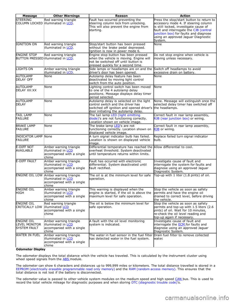
STEERING
COLUMN LOCKED Red warning triangle
illuminated in LCD. Fault has occurred preventing the
steering column lock from unlocking. This will also prevent the engine from
starting. Press the stop/start button to return to
accessory mode 4. If steering column
is still locked, investigate cause of
fault and interrogate the CJB (central junction box) for faults and diagnose
using an approved Jaguar Diagnostic System. IGNITION ON
Red warning triangle
illuminated in LCD. Stop/start button has been pressed
without the brake pedal depressed. Ignition is now in power mode 6. None ENGINE STOP
BUTTON PRESSED Red warning triangle
illuminated in LCD. Engine stop button has been pressed
when the vehicle is moving. Engine will
not be switched off until button is pressed quickly for a second time. Do not stop engine when vehicle is
moving unless necessary. LIGHTS ON
Amber warning triangle
illuminated in LCD. Side lamps or headlamps are on and the
driver's door has been opened. Switch off headlamps to avoid
excessive drain on battery. AUTOLAMP
DELAY OFF None
Autolamp delay feature has been
deactivated by moving light control
switch from the auto position. None AUTOLAMP
DELAY XX:XX None
Lighting control switch has been moved
to one of the 4 autolamp delay
positions. Message displays delay timer period selected. None AUTOLAMP
DELAY None
Autolamp delay is selected on the light
control switch and the driver has
switched off ignition and opened driver's
door initiating the autolamp delay. None. Message will extinguish once the
selected delay timer has switched off
the headlamps. TAIL LAMP
FAILURE None The tail lamp LED (light emitting
diode)'s are not functioning correctly.
Location shown on vehicle image. Correct fault in rear lamp assembly,
RJB (rear junction box) or wiring. BRAKE LAMP
FAILURE None The brake lamp LED's are not functioning correctly. Location shown on displayed vehicle image. Correct fault in rear lamp assembly,
RJB or wiring. INDICATOR LAMP
FAILURE None
A turn signal indicator bulb has failed.
Location is shown on displayed vehicle image. Replace failed turn signal indicator
bulb. E-DIFF NOT
AVAILABLE Amber warning triangle
illuminated in LCD accompanied with a single
chime Differential temperature has reached the
overheat threshold. System deactivated
until temperature returns within limits. Allow differential to cool. E-DIFF FAULT
Amber warning triangle
illuminated in LCD accompanied with a single
chime Fault has occurred with electronic
differential. System deactivated until
fault rectified. Investigate cause of fault and
interrogate the system for faults and
diagnose using an approved Jaguar Diagnostic System. ENGINE OIL LOW
Amber warning triangle
illuminated in LCD accompanied with a single
chime The oil is at the minimum level for safe
operation. Top-up with 1 liter (1.8 pints) of oil. ENGINE OIL
HIGH Amber warning triangle
illuminated in LCD accompanied with a single
chime This warning is displayed when the
engine is started, if the oil is above the
maximum level for safe operation. Stop the vehicle as soon as safety
permits and have the engine oil
drained to correct level, before driving
the vehicle. ENGINE OIL
CRITICALLY LOW Red warning triangle
illuminated LCD accompanied with a single
chime The oil is below the minimum level for
safe operation. Stop the vehicle as soon as safety
permits and top-up with 1.5 liters (2.6
pints) of oil. Wait for 10 minutes,
re-check the oil level reading and top-up again if necessary. ENGINE OIL
LEVEL MONITOR
SYSTEM FAULT Amber warning triangle
illuminated in LCD accompanied with a single
chime A fault with the oil level monitoring
system is indicated. Investigate cause of fault and
interrogate the ECM for faults and diagnose using an approved Jaguar Diagnostic System. WATER IN FUEL
Amber warning triangle
illuminated in LCD accompanied with a single
chime The water in fuel sensor in the fuel filter
has detected water in the fuel system. Drain fuel filter to remove collected
water. Odometer Display
The odometer displays the total distance which the vehicle has traveled. This is calculated by the instrument cluster using
wheel speed signals from the ABS module.
The odometer can show 6 characters and distances up to 999,999 miles or kilometers. The total distance travelled is stored in a
EEPROM (electrically erasable programmable read only memory) and the RAM (random access memory). This ensures that the
total distance is not lost if the battery is disconnected.
The odometer value is passed to other vehicle system modules on the medium speed and high speed CAN bus. This is used to record the total vehicle mileage for diagnostic purposes and when storing DTC (diagnostic trouble code)'s.
Page 1858 of 3039

NOTE: The vehicle may take 30 seconds (or 100m) to learn the steering centre position after starting the engine. This is
normal. 1 Start the engine 2 Wait at least 30 seconds 3 Select reverse gear 4 Turn the steering wheel and observe the touch screen Do the tracking lines react to steering input? Yes
No fault present
No
Potential LIN data gateway fault DTC Index
For a list of Diagnostic Trouble Codes (DTCs) that could be logged on this vehicle, please refer to Section 100-00.
Page 1867 of 3039
procedure.
NOTE: Under no circumstances should the battery be disconnected with the engine running because under these
conditions the generator can give a very high output voltage. This high transient voltage will damage the electronic
components in the vehicle. Loose or incomplete battery connections may also cause high transient voltage.
3. HEALTH AND SAFETY PRECAUTIONS
WARNINGS:
BATTERY CELLS CONTAIN SULPHURIC ACID AND EXPLOSIVE MIXTURES OF HYDROGEN AND OXYGEN GASES. IT IS
THEREFORE ESSENTIAL THAT THE FOLLOWING SAFETY PRECAUTIONS ARE OBSERVED.
Batteries emit highly explosive hydrogen at all times, particularly during charging. To prevent any potential form of
ignition occurring when working in the vicinity of a battery:
Do not smoke when working near batteries.
Avoid sparks, short circuits or other sources of ignition in the battery vicinity.
Switch off current before making or breaking electrical connections.
Ensure battery charging area is well ventilated.
Ensure the charger is switched off when: a) connecting to a battery; b) disconnecting from the battery.
Always disconnect the ground cable from the battery terminal first and reconnect it last.
Batteries contain poisonous and highly corrosive acid. To prevent personal injury, or damage to clothing or the vehicle,
the following working practices should be followed when topping up, checking electrolyte specific gravity, removal, refitting or
carrying batteries:
Always wear suitable protective clothing (an apron or similar), safety glasses, a face mask and suitable gloves.
If acid is spilled or splashed onto clothing or the body, it must be neutralized immediately and then rinsed with clean
water. A solution of baking soda or household ammonia and water may be used as a neutralizer.
In the event of contact with the skin, drench the affected area with water. In the case of contact with the eyes, bathe
the affected area with cool clean water for approximately 15 minutes and seek urgent medical attention.
If battery acid is spilled or splashed on any surface of a vehicle, it should be neutralized and rinsed with clean water.
Heat is generated when acid is mixed with water. If it becomes necessary to prepare electrolyte of a desired specific
gravity, SLOWLY pour the concentrated acid into water (not water into acid), adding small amounts of acid while
stirring. Allow the electrolyte to cool if noticeable heat develops. With the exception of lead or lead-lined containers,
always use non-metallic receptacles or funnels. Do not store acid in excessively warm locations or in direct sunlight.
Due to their hazardous contents, the disposal of batteries is strictly controlled. When a battery is scrapped, ensure it is
disposed of safely, complying with local environmental regulations. If in doubt, contact your local authority for advice on
disposal facilities.
4. BATTERY CARE REQUIREMENTS
4.1 RECEIPT OF A NEW VEHICLE
Within 24 hours of receipt of a new vehicle, a battery condition check must be carried out in accordance with the battery test
process utilizing a JLR approved tester as outlined in the Equipment section (Section 5) of this procedure.
NOTE: The Midtronics code from the tester must be recorded on the form.
Any actions must be carried out in accordance with the table shown in the Determining Battery Condition section (Section 6)
of this procedure. The details must be recorded on the New Vehicle Storage Form which is part of the new vehicle storage
document.
For additional information, refer to: New Vehicle Storage Form (100-11 Vehicle Transportation Aids and Vehicle Storage, Description and Operation).
4.2 NEW VEHICLE STORAGE
If the vehicle is to be stored the transit relays MUST be refitted and / or the vehicle put into transport mode.
Transit relay removal / vehicle placed in normal mode should only be completed a maximum of 72 hours prior to handover to
customer
For vehicles without either a transit mode or transit relay the battery negative cable must be DISCONNECTED from the battery.
The battery must be tested and/or re-charged every 30 days and MUST be re-charged after every 90 day period.
NOTE: The Midtronics code from the tester must be recorded on the form. www.JagDocs.com
Page 1868 of 3039
Any actions must be carried out in accordance with the table shown in the Determining Battery Condition section (Section 6)
of this procedure. The details must be recorded on the New Vehicle Storage Form which is part of the new vehicle storage
document.
For additional information, refer to: New Vehicle Storage Form (100-11 Vehicle Transportation Aids and Vehicle Storage, Description and Operation).
4.3 PDI / DELIVERY TO CUSTOMER
Before the vehicle is handed over to the customer and as part of the PDI, the condition of the battery needs to be confirmed.
The battery condition must be checked in accordance with the battery test process utilizing a JLR approved tester as outlined
in the Equipment section (Section 5) of this procedure.
NOTE: The Midtronics code from the tester must be recorded on the form.
Any actions must be carried out in accordance with the table shown in the Determining Battery Condition section (Section 6)
of this procedure. The details must be recorded on the New Vehicle Storage Form which is part of the new vehicle storage
document.
For additional information, refer to: New Vehicle Storage Form (100-11 Vehicle Transportation Aids and Vehicle Storage, Description and Operation).
4.4 REPLACEMENT BATTERIES FOR SERVICE
All service replacement batteries must have the battery condition checked within 24 hours of receipt and controlled on a ‘First
In First Out’ basis to ensure batteries are not allowed to age unnecessarily.
For batteries in storage and not yet fitted to a vehicle, they must be stored in a dry environment, not in direct sunlight or
under any direct heat source. Any batteries exhibiting any forms of damage or corrosion must not be fitted to any vehicle. Any
batteries which are dropped must be scrapped, this applies even if no external damage is apparent.
The battery condition must be checked every 30 days in accordance with the battery test process utilizing a JLR approved
tester as outlined in the Equipment section (Section 5) of this procedure.
Any actions must be carried out in accordance with the table shown in the Determining Battery Condition section (Section 6)
of this procedure.The details must be recorded on the New Vehicle Storage Form which is part of the new vehicle storage
document.
For additional information, refer to: New Vehicle Storage Form (100-11 Vehicle Transportation Aids and Vehicle Storage, Description and Operation).
4.5 BATTERY MAINTENANCE
Any battery whether it is in a vehicle or a replacement part must be tested and/or re-charged every 30 days and MUST be
re-charged after every 90 day period.
4.6 BATTERY TEST PROCESS
It is recommended that this test is conducted at least 24 hours after the vehicle engine has been run or the battery charged to
avoid the need of surface charge removal. If time constraints make this unacceptable then the surface charge must be
removed.
Surface Charge Removal
A vehicle which has had its battery charged or been driven in a 24 hour period before the test, must have its surface charge
removed.
Turn on the ignition (power mode 6) but do not start the vehicle
Switch on the headlamps on high beam for a minimum 3 minutes
Switch off the headlamps
Wait a minimum of 5 minutes before recording test results for any battery measurements
Battery Test
The battery may be tested either on a bench or on the vehicle.
The battery condition must be checked in accordance with the battery test process utilizing a JLR approved tester as outlined
in the Equipment section (Section 5) of this procedure.
NOTE: The Midtronics code from the tester must be recorded on the form.
Any actions must be carried out in accordance with the table shown in the Determining Battery Condition section (Section 6)
of this procedure. The details must be recorded on the New Vehicle Storage Form which is part of the new vehicle storage
document.
For additional information, refer to: New Vehicle Storage Form (100-11 Vehicle Transportation Aids and Vehicle Storage, Description and Operation).
CAUTION: DO NOT connect the tester to any other circuit or chassis point other than the battery negative terminal.
Page 1871 of 3039
Published: 21-Dec-2012
Battery and Charging System - General Information - Quiescent Drain
Description and Operation
VEHICLE QUIESCENT CURRENT TESTING
On vehicles fitted with a Battery Monitoring System (BMS), the diagnostic routine for quiescent drain testing in the approved
Jaguar or Land Rover diagnostic system should be utilized.
If a customer complains of a vehicle battery that discharges continuously or when left for a prolonged period of time, it is
recommended that a quiescent drain test is performed as described below.
The battery drain should be measured using the approved Jaguar or Land Rover diagnostic system or a Digital Multi-Meter
(DVOM). A procedure for quiescent drain measurement using the diagnostic system is available in the Diagnosis and Testing
section of the Workshop Manual. The vehicle should be in the locked/armed state (for example vehicle alarm fully armed), all
doors, engine and luggage compartment lids are open and latched (so as to appear closed from an electrical point of view).
The test should take place after the vehicle has entered shutdown mode. The time taken for this to occur after the ignition is
switched off varies according to model (Refer to the Topix On line resource for details).
When the vehicle is armed, the effect of the security system Light Emitting Diode (LED) flashing is to cause a pulsation in the
measured current drain. In this case, either the average current should be taken (using a Digital Multi- Meter (DVOM) with an
averaging system) or the current reading taken, ignoring the brief high current peaks.
EQUIPMENT
Approved Jaguar or Land Rover diagnostic system with current probeOR Digital Multi-Meter (DVOM) with current probe.
METHOD OF MEASUREMENT
Using an Approved Jaguar or Land Rover Diagnostic System.
1. Switch off all electrical loads and ensure that the ignition is off
2. Connect the current probe to the approved Jaguar or Land Rover diagnostic system
3. Calibrate the probe
4. Install a clamp around the battery lead/junction box lead
5. Go to the Quiescent Current Testing section in this procedure
Using a digital multimeter
Do not use an in-line DVOM to measure the quiescent drain on vehicles fitted with an electronic throttle (for example XK 2006
onwards). The current exceeds the maximum amount the fuse in the DVOM is capable of handling.
1. Switch off all electrical loads and ensure that the ignition is off
2. Connect the current probe to the digital multmeter
3. Calibrate the probe
4. Install a clamp around the battery lead/junction box lead
5. Go to the Quiescent Current Testing section in this procedure
QUIESCENT CURRENT TESTING
1. Switch ignition to ‘on’ or select ignition mode in keyless vehicles and switch to ‘off’ (do not crank)
2. Remove key from ignition switch (if equipped)
3. Open and latch all doors, hood and luggage compartment lid
4. Lock the vehicle using the remote function on the remote handset. (Single lock only to avoid volumetric alarm arming)
5. Remove any other potential electrical drains such as accessories plugged into accessory sockets
6. Record the amperage readings after the shutdown period referenced in the Topix on line resource for details. Note all
cars from 10MY onwards and XK from 07MY and XF from 08MY should be less than 30mA after 30 minutes
7. Record the final reading on the battery report form
The preferred method of testing following an excessive current consumption figure is to use a current probe around individual
junction box leads to the various suspected circuits to identify a potential cause. This is in preference to the old method of
removing fuses for the following reasons:
The drain may be caused by a module remaining active and preventing the quiescent drain from reducing to normal
levels
The drain may be caused by a relay winding that is activated. Pulling the fuse can allow this to ‘reset’ and the drain will
be lost and go un-diagnosed
QUIESCENT DRAIN - TYPICAL VALUES
NOTE: The quiescent drain after the initial shutdown period should not exceed the value shown in the table.
Jaguar Quiescent Drain Values
MODEL SHUT DOWN PERIOD (minutes) TYPICAL VALUES BATTERY DRAIN (mA) XJS 3.2 60 <30 Sovereign 3.2 60 <37.3
Page 1873 of 3039
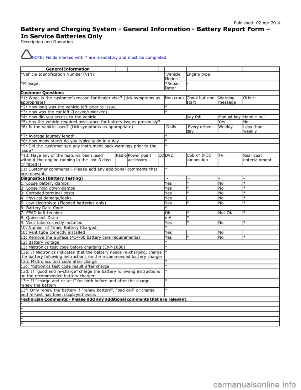
Published: 02-Apr-2014
Battery and Charging System - General Information - Battery Report Form – In Service Batteries Only
Description and Operation
NOTE: Fields marked with * are mandatory and must be completed.
General Information *Vehicle Identification Number (VIN):
Vehicle
Model: Engine type: *Mileage:
*Repair
Date: - Customer Questions *1: What is the customer’s reason for dealer visit? (tick symptoms as appropriate) Non crank
Crank but non
start Warning message Other: *2: How long was the vehicle left prior to issue. * *3: How was the car left (Locked/unlocked) * *4: How did you access to the vehicle Key fob Manual key Handle pull *5: Has the vehicle required assistance for battery issues previously? Yes No *6: Is the vehicle used? (tick symptoms as appropriate) Daily
Every other day Weekly
Less than weekly *7: Average journey length * *8: How many starts do you typically do in a day * *9: Did the customer see any instrument pack warnings prior to the
issue? * *10: Have any of the features been used
without the engine running in the last 3 days (if fitted?) Radio
Power point
accessory CD DVD USB or IPOD
connection TV
Rear seat
entertainment 11: Customer comments:- Please add any additional comments that
are relevant. * Diagnostics (Battery Testing) - - - - 1: Loose battery clamps Yes * No * 2: Loose hold down clamps Yes * No * 3: Corroded terminal posts Yes * No * 4: Physical damage/leaks Yes No * 5: Low electrolyte (Flooded batteries only) Yes * No * 6: Battery Date Code * 7: FEAD belt tension OK * Not OK * 8: Quiescent Drain mA * 9: Vent tube correctly installed Yes * No * 10: Number of Times Battery Charged: * 10: Vent tube correctly installed Yes No 11: Remove the Surface (414-00 battery care requirements) Yes * No * 12: Battery voltage * 13: Midtronics test code before charging (EXP-1080) * 13a: If Midtronics indicates that the battery needs re-charging, charge
the battery following instructions on the recommended battery charger * 13b: Midtronics test code after charge * 13c: Midtronics test code result after charge * 13d: If "good and re-charge" charge the battery following instructions
on the recommended battery charger * 13e: If "charge and re-test" for both before and after the charge
renew the battery * 13f: Only renew the battery if "renew battery", "bad cell" or charge
and re-test has been displayed twice. * Technician Comments:- Please add any additional comments that are relevant. * * * * *