JAGUAR XFR 2010 1.G Workshop Manual
XFR 2010 1.G
JAGUAR
JAGUAR
https://www.carmanualsonline.info/img/21/7642/w960_7642-0.png
JAGUAR XFR 2010 1.G Workshop Manual
Trending: 414-01, fuel pressure, PID, wiper fluid, light, key fob, infotainment
Page 571 of 3039
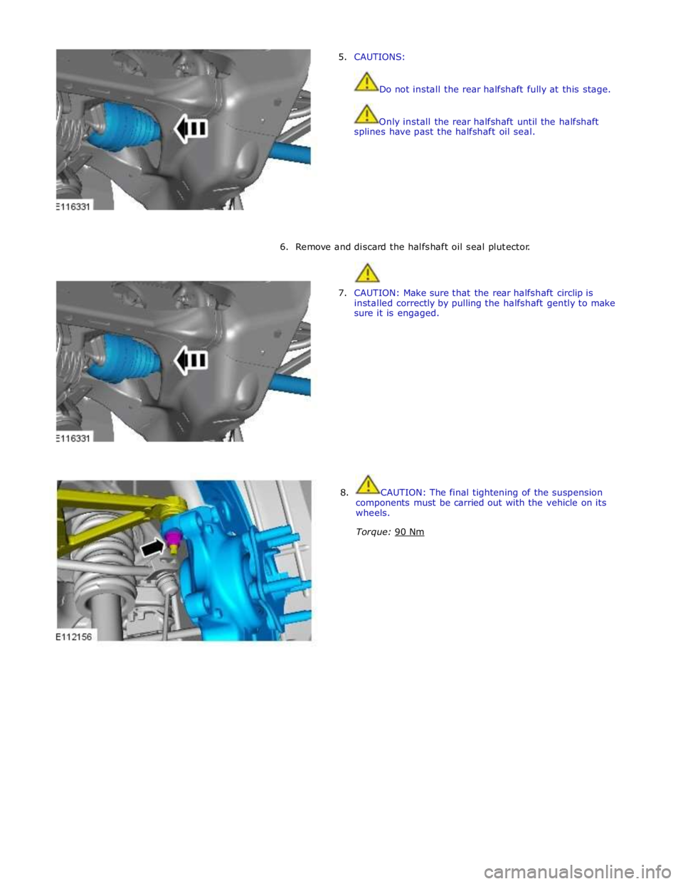
5. CAUTIONS:
Do not install the rear halfshaft fully at this stage.
Only install the rear halfshaft until the halfshaft
splines have past the halfshaft oil seal.
6. Remove and discard the halfshaft oil seal plutector.
7. CAUTION: Make sure that the rear halfshaft circlip is
installed correctly by pulling the halfshaft gently to make
sure it is engaged.
8. CAUTION: The final tightening of the suspension
components must be carried out with the vehicle on its
wheels.
Torque: 90 Nm
Page 572 of 3039
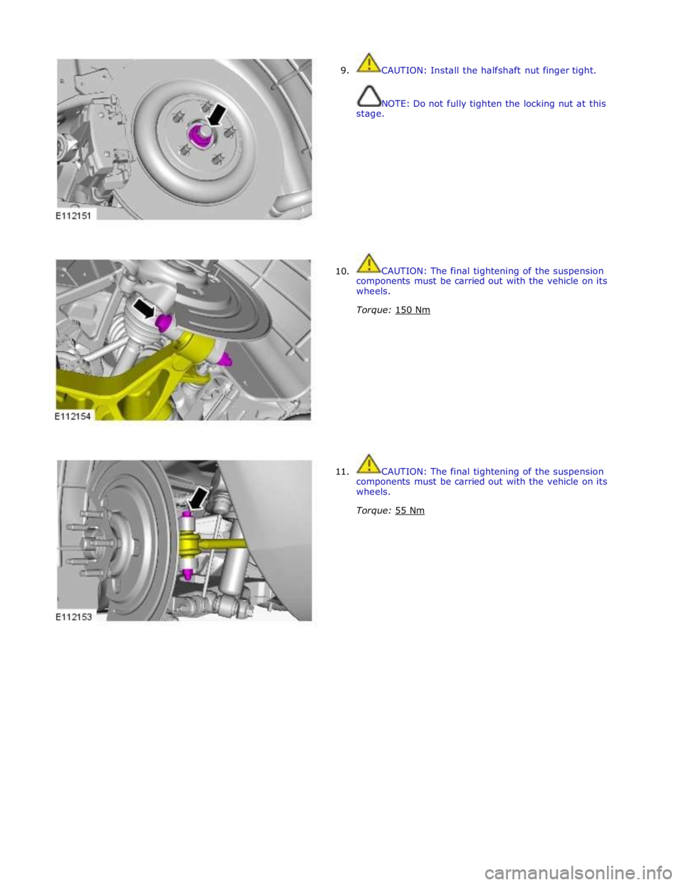
9.
10.
11. CAUTION: Install the halfshaft nut finger tight.
NOTE: Do not fully tighten the locking nut at this
stage.
CAUTION: The final tightening of the suspension
components must be carried out with the vehicle on its
wheels.
Torque: 150 Nm
CAUTION: The final tightening of the suspension
components must be carried out with the vehicle on its
wheels.
Torque: 55 Nm
Page 573 of 3039
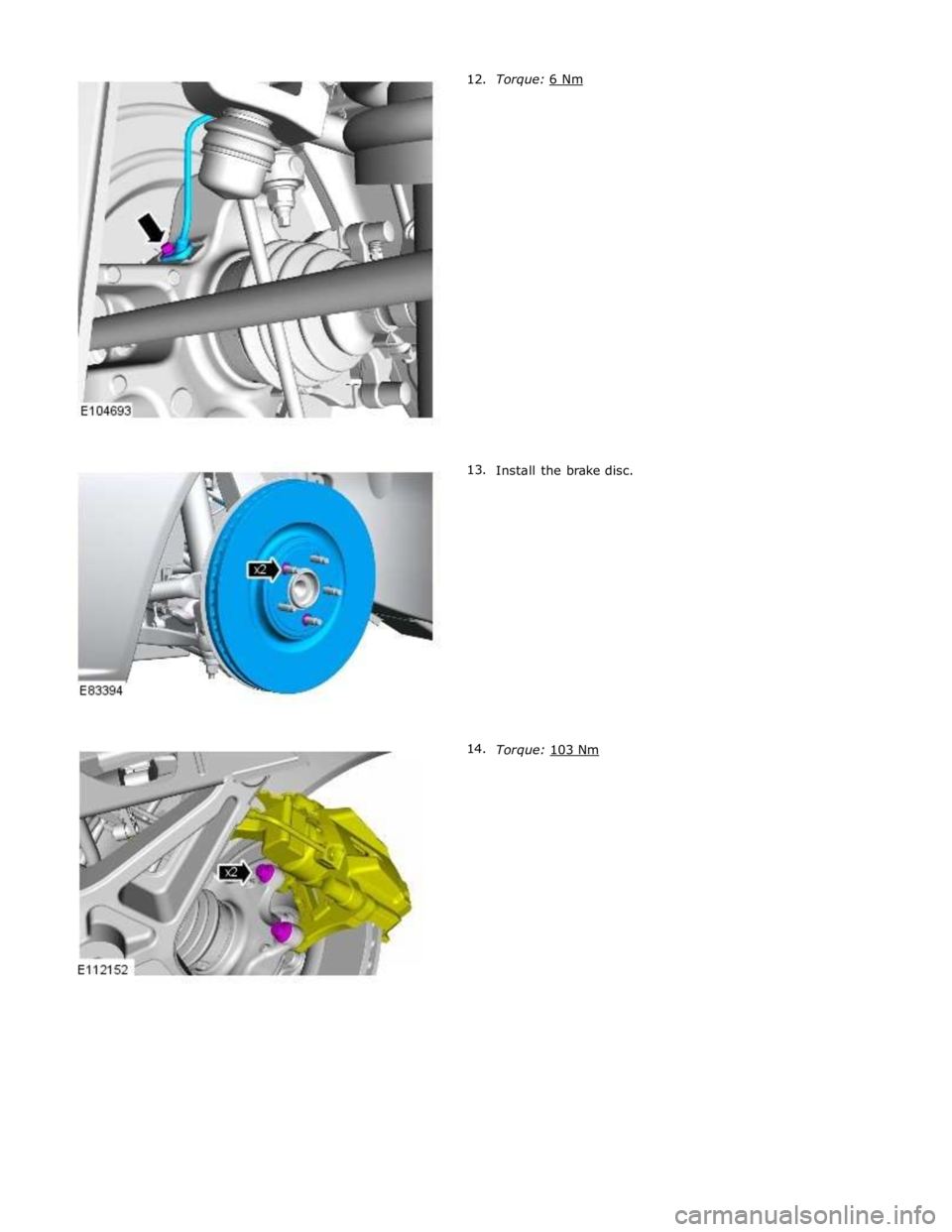
Install the brake disc.
Torque: 103 Nm
Page 574 of 3039
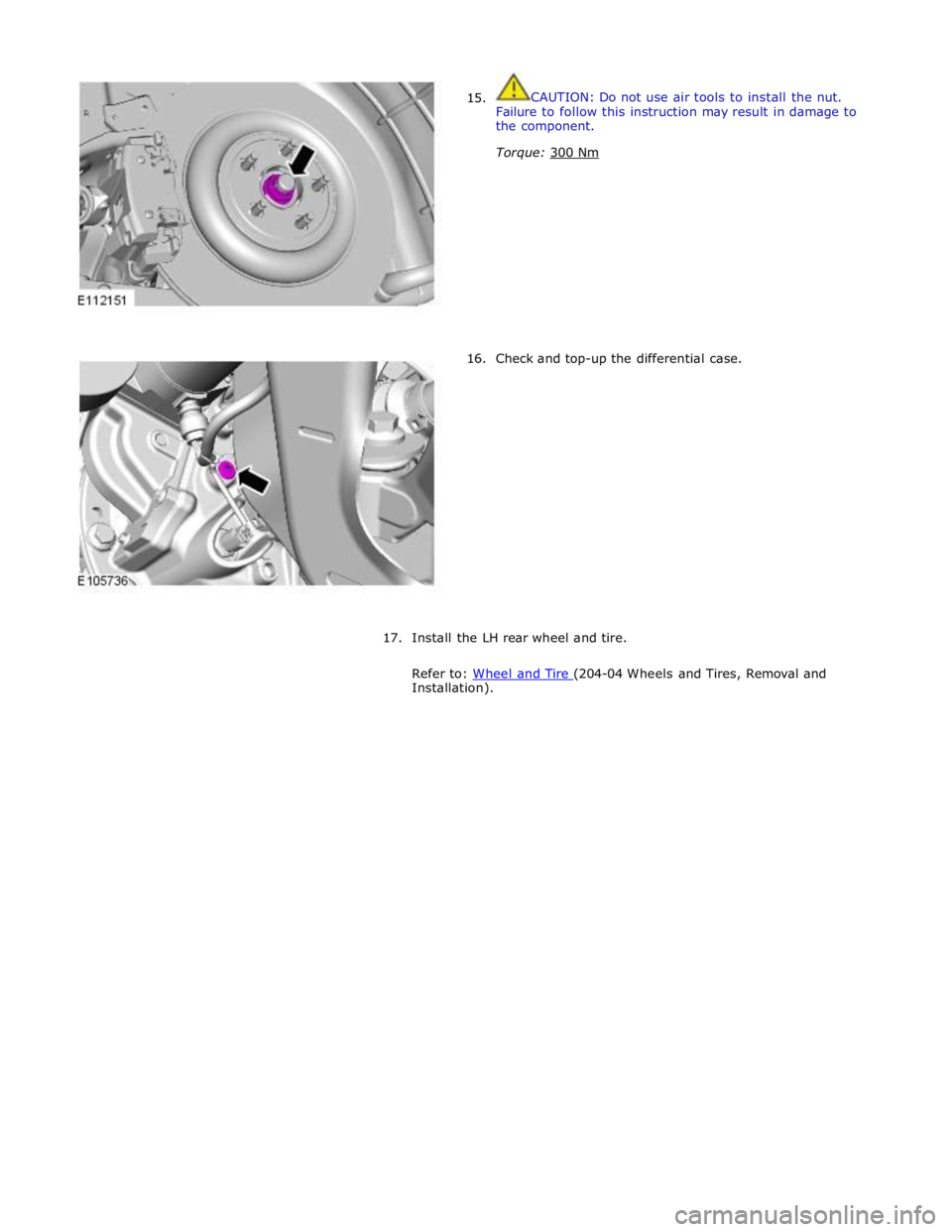
15.
16. CAUTION: Do not use air tools to install the nut.
Failure to follow this instruction may result in damage to
the component.
Torque: 300 Nm
Check and top-up the differential case.
17.
Install the LH rear wheel and tire.
Refer to: Wheel and Tire (204-04 Wheels and Tires, Removal and Installation).
Page 575 of 3039
Rear Drive Halfshafts - Inner Constant Velocity (CV) Joint Boot
Removal and Installation
Removal Published: 11-May-2011
1. WARNING: Do not work on or under a vehicle supported only by a
jack. Always support the vehicle on safety stands.
Raise and support the vehicle.
2. Remove the rear halfshaft.
For additional information, refer to: Rear Halfshaft - TDV6 3.0L Diesel /V8 5.0L Petrol/V8 S/C 5.0L Petrol (205-05 Rear Drive Halfshafts, Removal and Installation).
3. CAUTION: Use suitable protective covers to protect the halfshaft.
Using a suitable clamp, secure the rear halfshaft.
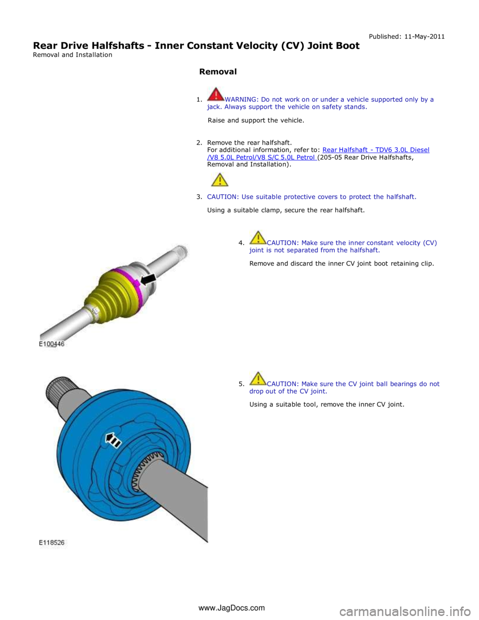
4. CAUTION: Make sure the inner constant velocity (CV)
joint is not separated from the halfshaft.
Remove and discard the inner CV joint boot retaining clip.
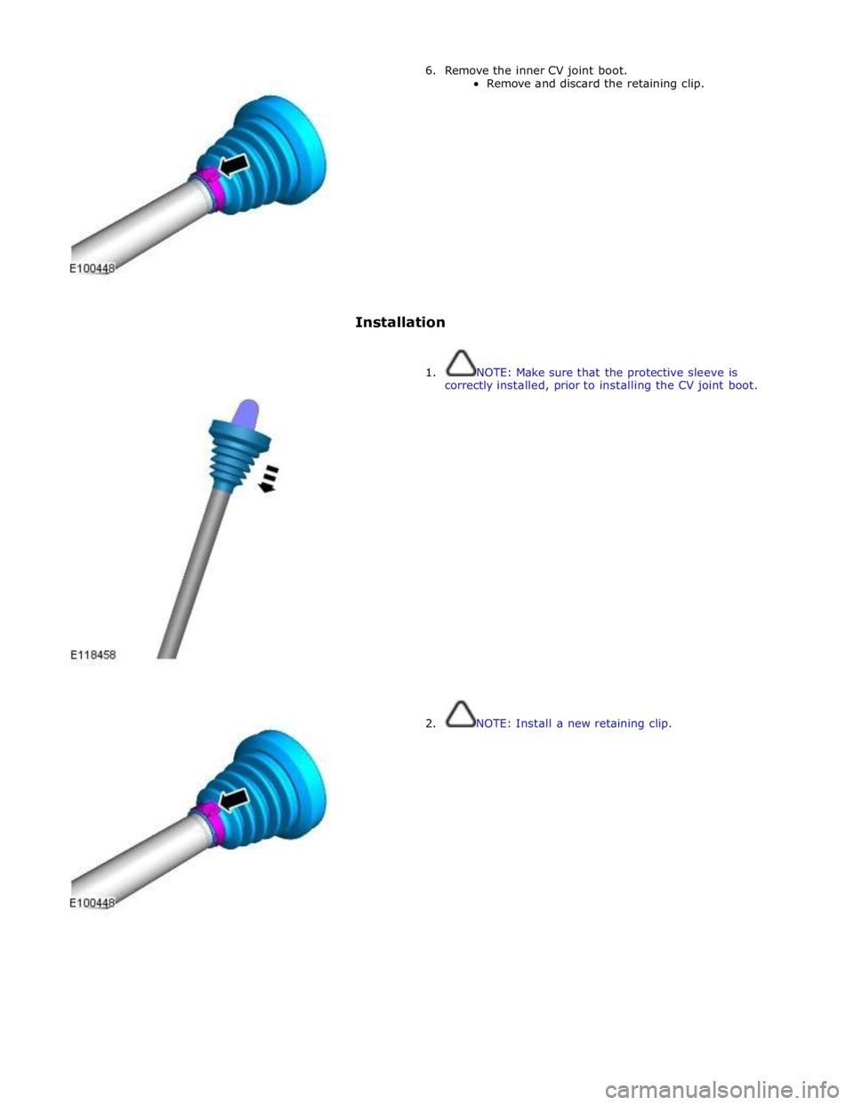
5. CAUTION: Make sure the CV joint ball bearings do not
drop out of the CV joint.
Using a suitable tool, remove the inner CV joint. www.JagDocs.com
Page 576 of 3039
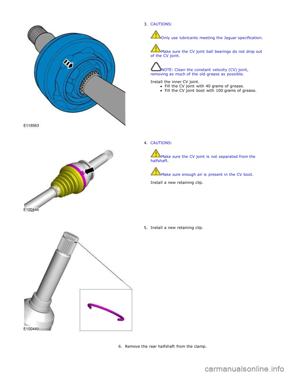
6. Remove the inner CV joint boot.
Remove and discard the retaining clip.
Installation
1. NOTE: Make sure that the protective sleeve is
correctly installed, prior to installing the CV joint boot.
2. NOTE: Install a new retaining clip.
Page 577 of 3039
3. CAUTIONS:
Only use lubricants meeting the Jaguar specification.
Make sure the CV joint ball bearings do not drop out
of the CV joint.
NOTE: Clean the constant velocity (CV) joint,
removing as much of the old grease as possible.
Install the inner CV joint.
Fill the CV joint with 40 grams of grease.
Fill the CV joint boot with 100 grams of grease.
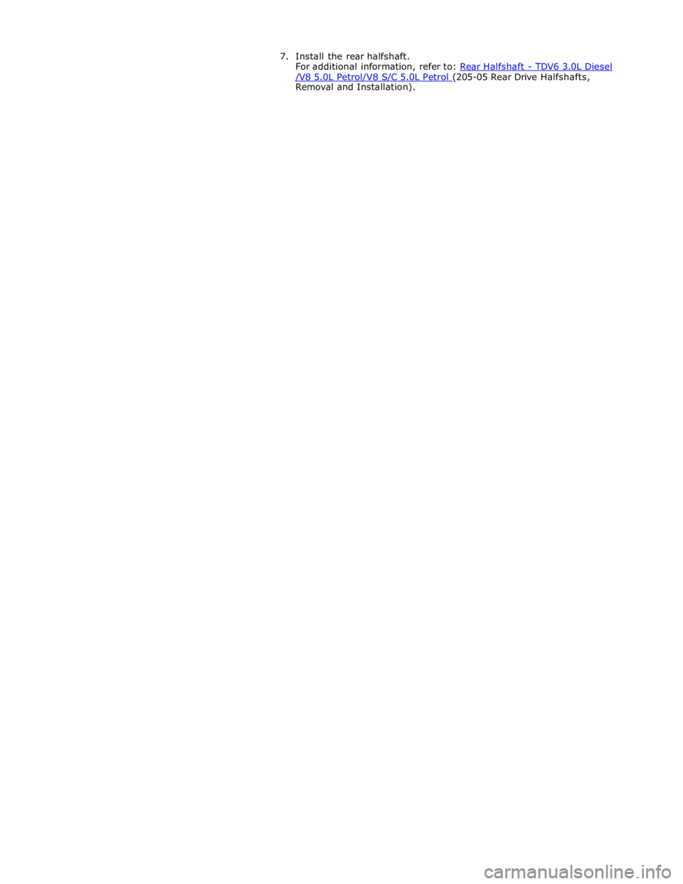
4. CAUTIONS:
Make sure the CV joint is not separated from the
halfshaft.
Make sure enough air is present in the CV boot.
Install a new retaining clip.
5. Install a new retaining clip.
6. Remove the rear halfshaft from the clamp.
Page 578 of 3039
/V8 5.0L Petrol/V8 S/C 5.0L Petrol (205-05 Rear Drive Halfshafts, Removal and Installation).
Page 579 of 3039
Rear Drive Halfshafts - Outer Constant Velocity (CV) Joint Boot
Removal and Installation
Removal Published: 11-May-2011
1. WARNING: Do not work on or under a vehicle supported only by a
jack. Always support the vehicle on safety stands.
Raise and support the vehicle.
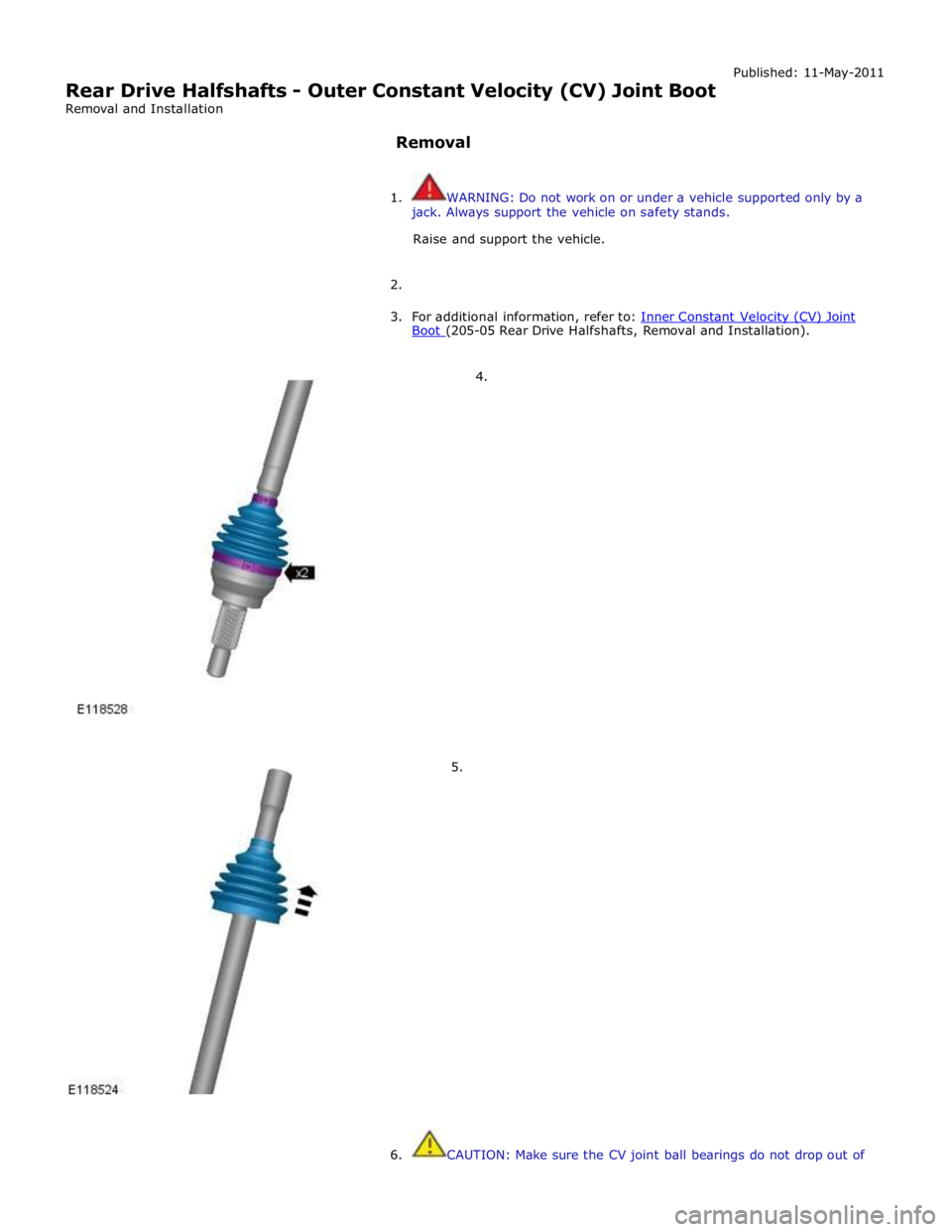
2.
3. For additional information, refer to: Inner Constant Velocity (CV) Joint Boot (205-05 Rear Drive Halfshafts, Removal and Installation).
4.
5.
6. CAUTION: Make sure the CV joint ball bearings do not drop out of
Page 580 of 3039
the CV joint.
NOTE: Clean the constant velocity (CV) joint, removing as much of
the old grease as possible.
Installation
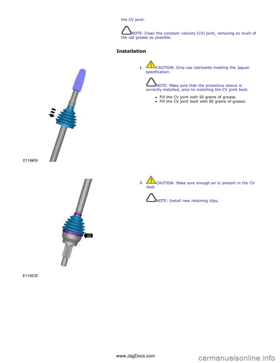
1. CAUTION: Only use lubricants meeting the Jaguar
specification.
NOTE: Make sure that the protective sleeve is
correctly installed, prior to installing the CV joint boot.
Fill the CV joint with 50 grams of grease.
Fill the CV joint boot with 85 grams of grease.
2. boot.
CAUTION: Make sure enough air is present in the CV
NOTE: Install new retaining clips. www.JagDocs.com
Trending: refuelling, fuse diagram, u0424-00, open gas tank, wiper, alarm, Pedestrian protection
