climate control JAGUAR XFR 2010 1.G Repair Manual
[x] Cancel search | Manufacturer: JAGUAR, Model Year: 2010, Model line: XFR, Model: JAGUAR XFR 2010 1.GPages: 3039, PDF Size: 58.49 MB
Page 1704 of 3039

Climate Control - Control Components - Component Location
Description and Operation
NOTE: RHD (right-hand drive) vehicle shown, LHD (left-hand drive) vehicle similar.
Component Location Published: 29-May-2014
Item Description 1 Pollution sensor Comments:
where fitted 2 Sunload sensor 3 Ambient air temperature sensor 4 Windshield (Defrost) distribution stepper motor 5 Evaporator temperature sensor
Page 1706 of 3039
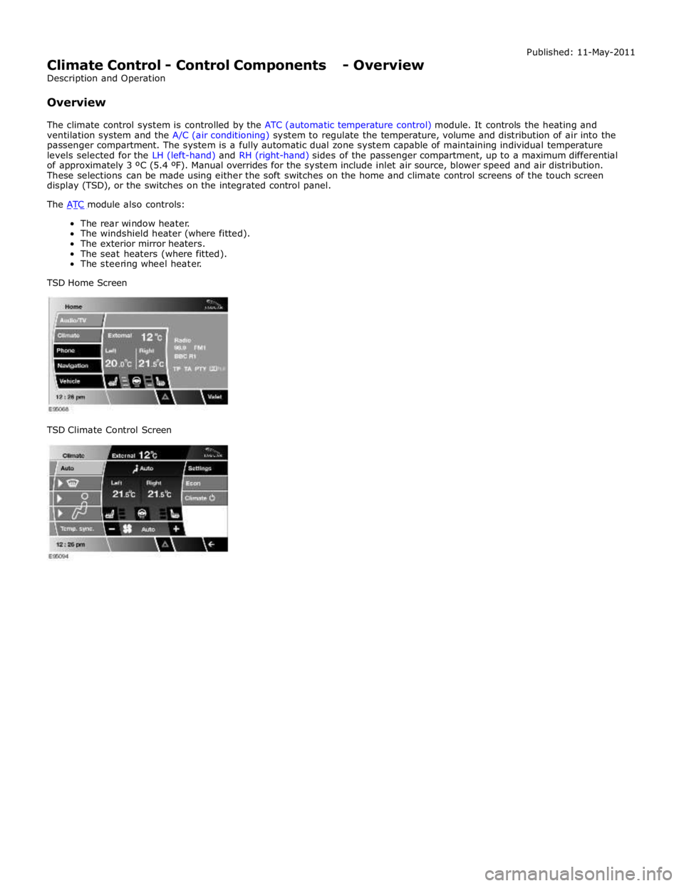
Climate Control - Control Components - Overview
Description and Operation
Overview Published: 11-May-2011
The climate control system is controlled by the ATC (automatic temperature control) module. It controls the heating and
ventilation system and the A/C (air conditioning) system to regulate the temperature, volume and distribution of air into the
passenger compartment. The system is a fully automatic dual zone system capable of maintaining individual temperature
levels selected for the LH (left-hand) and RH (right-hand) sides of the passenger compartment, up to a maximum differential
of approximately 3 ºC (5.4 ºF). Manual overrides for the system include inlet air source, blower speed and air distribution.
These selections can be made using either the soft switches on the home and climate control screens of the touch screen
display (TSD), or the switches on the integrated control panel.
The ATC module also controls: The rear window heater.
The windshield heater (where fitted).
The exterior mirror heaters.
The seat heaters (where fitted).
The steering wheel heater.
TSD Home Screen
TSD Climate Control Screen
Page 1707 of 3039
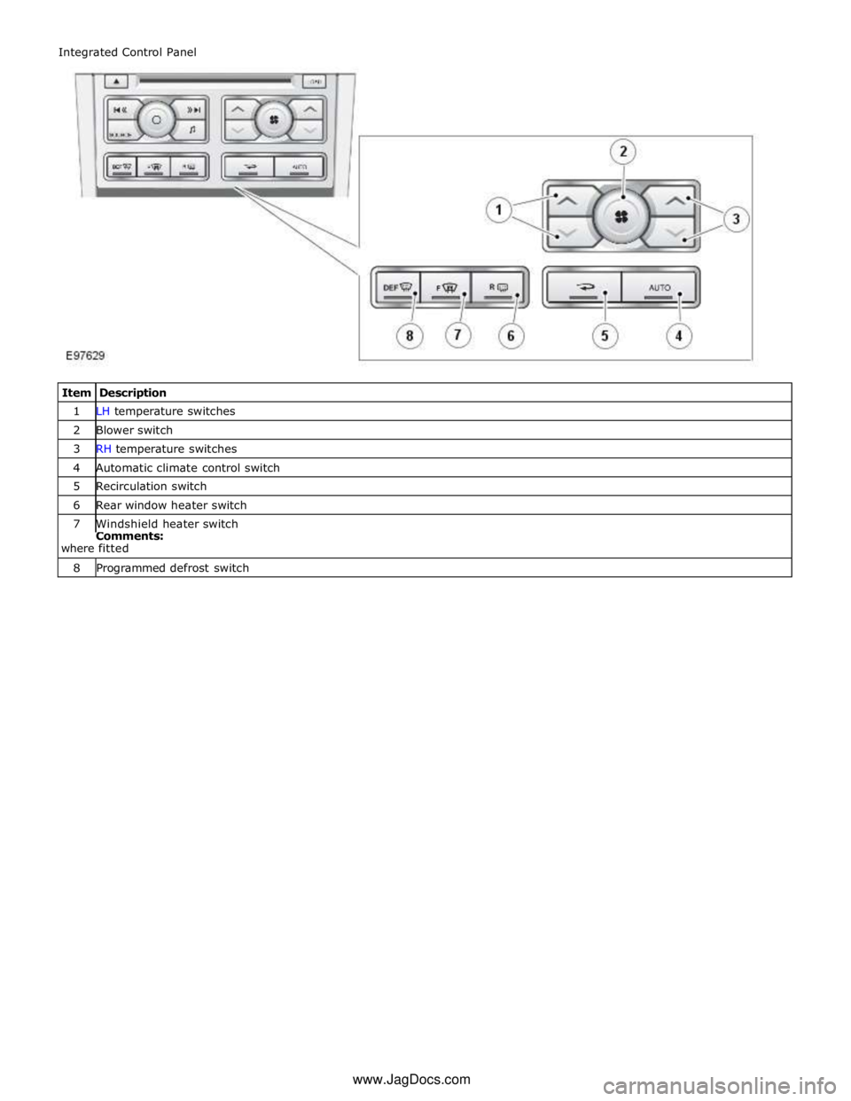
1 LH temperature switches 2 Blower switch 3 RH temperature switches 4 Automatic climate control switch 5 Recirculation switch 6 Rear window heater switch 7 Windshield heater switch Comments:
where fitted 8 Programmed defrost switch Integrated Control Panel
www.JagDocs.com
Page 1708 of 3039
Published: 11-May-2011
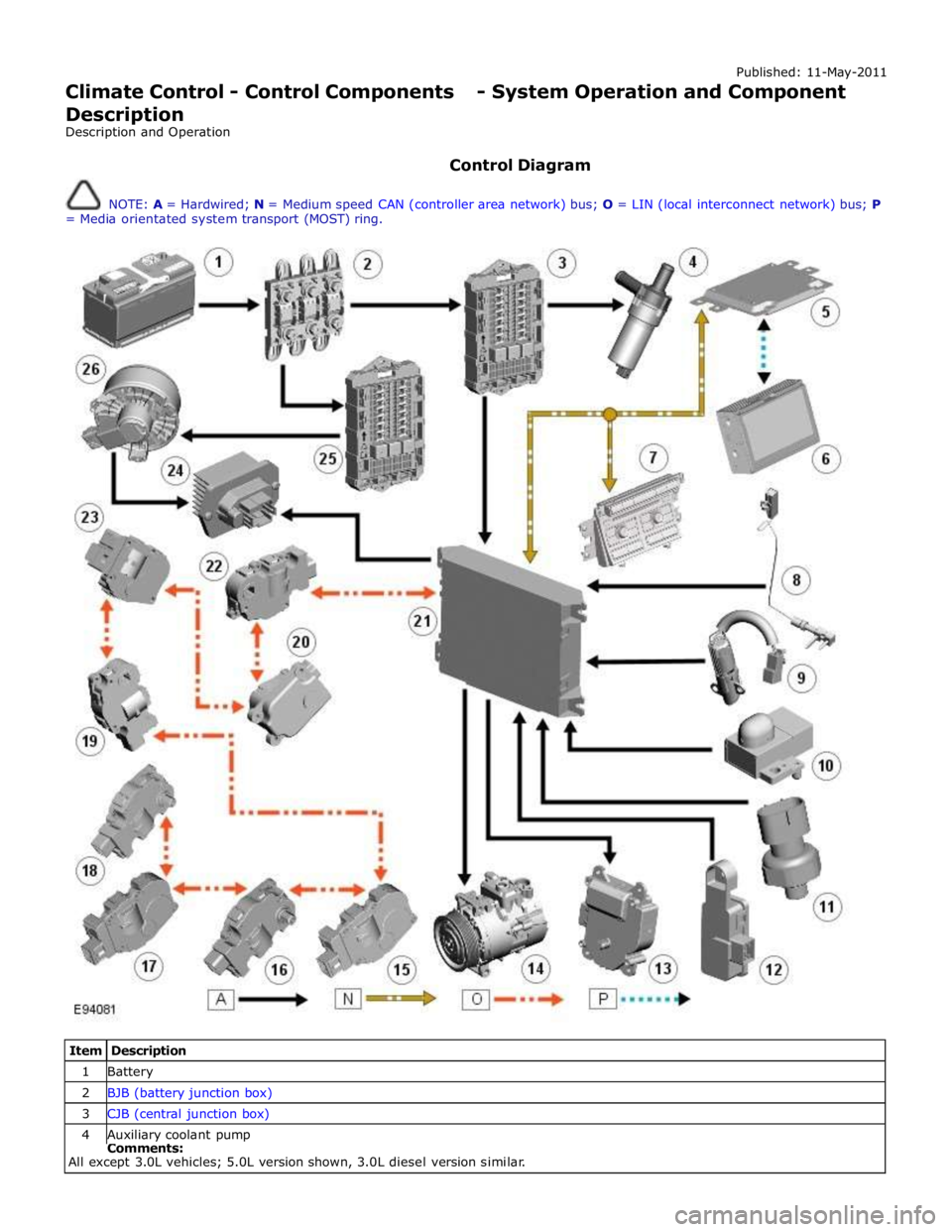
Climate Control - Control Components - System Operation and Component Description
Description and Operation
Control Diagram
NOTE: A = Hardwired; N = Medium speed CAN (controller area network) bus; O = LIN (local interconnect network) bus; P
= Media orientated system transport (MOST) ring.
Item Description 1 Battery 2 BJB (battery junction box) 3 CJB (central junction box) 4 Auxiliary coolant pump Comments:
All except 3.0L vehicles; 5.0L version shown, 3.0L diesel version similar.
Page 1711 of 3039
rear window heater switch is pressed or the engine stops.
Automatic operation during a journey is initiated when low ambient air temperatures are experienced and the vehicle has been
travelling for a set period of time above a threshold speed. In this instance, no feedback is given to the driver to inform him
the rear window heater is operational (the switch LED is not illuminated). The duration of heater operation is variable depending on the ambient air temperature, vehicle speed and the amount of time the vehicle has been travelling.
Windshield Heater (Where Fitted)
Windshield heater operation is only enabled when the engine is running. The ATC module controls operation of the windshield heater using two relays in the EJB (engine junction box). When windshield heater operation is required, the ATC module broadcasts a message to the CJB on the medium speed CAN bus. On receipt of the message, the CJB energizes the relays by providing a ground path for both relay coils. This allows a battery feed to flow across the relays to power the windshield left
and right heater elements.
There are two modes of windshield heater operation; manual and automatic.
Manual operation is activated by pressing the windshield heater switch on the integrated control panel. When the switch is
pressed, the status LED in the switch illuminates and the windshield heater elements are energized. Manual operation is discontinued when the windshield heater switch is pressed a second time, 5 minutes have elapsed (the heating phase), or the
engine stops. If manual operation is discontinued by the engine stopping, the previous heating phase is resumed if the engine
is re-started within 30 seconds.
There are two variants of automatic operation; automatic operation at the start of a journey and automatic operation during a
journey.
Automatic operation at the start of a journey is initiated if the ambient air temperature is below 5 °C (41 °F). In this instance,
the switch LED is illuminated and the heater elements are energized for 6.5 minutes. Automatic operation is discontinued if the windshield heater switch is pressed or the engine stops.
Automatic operation during a journey is initiated when low ambient air temperatures are experienced and the vehicle has been
travelling for a set period of time above a threshold speed. In this instance, no feedback is given to the driver to inform him
the windshield heater is operational (the switch LED is not illuminated) and the duration of operation is variable depending upon the ambient air temperature, vehicle speed and the amount of time the vehicle has been travelling.
Exterior Mirror Heaters
Operation of the exterior mirror heaters is fully automatic and not controllable by the driver. Exterior mirror heater operation is
determined by ambient air temperature and windshield wiper status. When ambient air temperature reaches a pre-determined
level, the ATC module broadcasts an exterior mirror heating request to the door modules over the medium speed CAN bus. On receipt of this message, the door modules provide feed and ground connections to both exterior mirror heater elements.
The amount of time the exterior mirror heaters are operational increases if the windshield wipers are switched on. This ensures
the mirrors remain mist free in damp and wet conditions, where there is an increased risk of misting.
Seat Heaters (Where Fitted)
There are four seat heater settings available; off, 1, 2 and 3, which can be selected on the home and climate control screens
of the TSD. The heat setting is relayed to the vehicle occupants through a graduated display on the TSD.
Operation of the heated seats is controlled by the ATC module. When the ATC module receives a heating request from the TSD, it broadcasts a message to the CJB over the medium speed CAN bus. The CJB then provides a hardwired 12 V supply to the three heater elements in the related front seat. The heater elements, two in the seat cushion and one in the seat squab,
are wired in series. The ATC module monitors seat temperature using a temperature sensor located in each seat cushion. The CJB provides the temperature sensors with a 5 V supply. The level of the returned voltage back to the CJB is proportional to the seat temperature. The value of the return signal is broadcast to the ATC module, over the medium speed CAN bus, which allows it to control the seat temperature to the required level. The ATC module will suspend or disable operation of the seat heaters if any of the following occur:
Battery voltage exceeds 16.5 ± 0.3 V for more than 5 seconds. Seat heating is re-enabled when battery voltage
decreases to 16.2 ± 0.3 V.
If a short or open circuit is detected.
If the seat heat temperature rises significantly above the target temperature setting.
The graduated display on the TSD remains illuminated until the seat heaters are turned off or the engine stops. If the engine
is restarted within 30 seconds the seat heater resumes the previous heating level.
Page 1717 of 3039

Climate Control - Ambient Air Temperature Sensor
Removal and Installation
Removal
NOTE: Removal steps in this procedure may contain installation details. Published: 11-May-2011
1. Refer to: Exterior Mirror Cover (501-09 Rear View Mirrors, Removal and Installation).
2.
3. www.JagDocs.com
Page 1719 of 3039
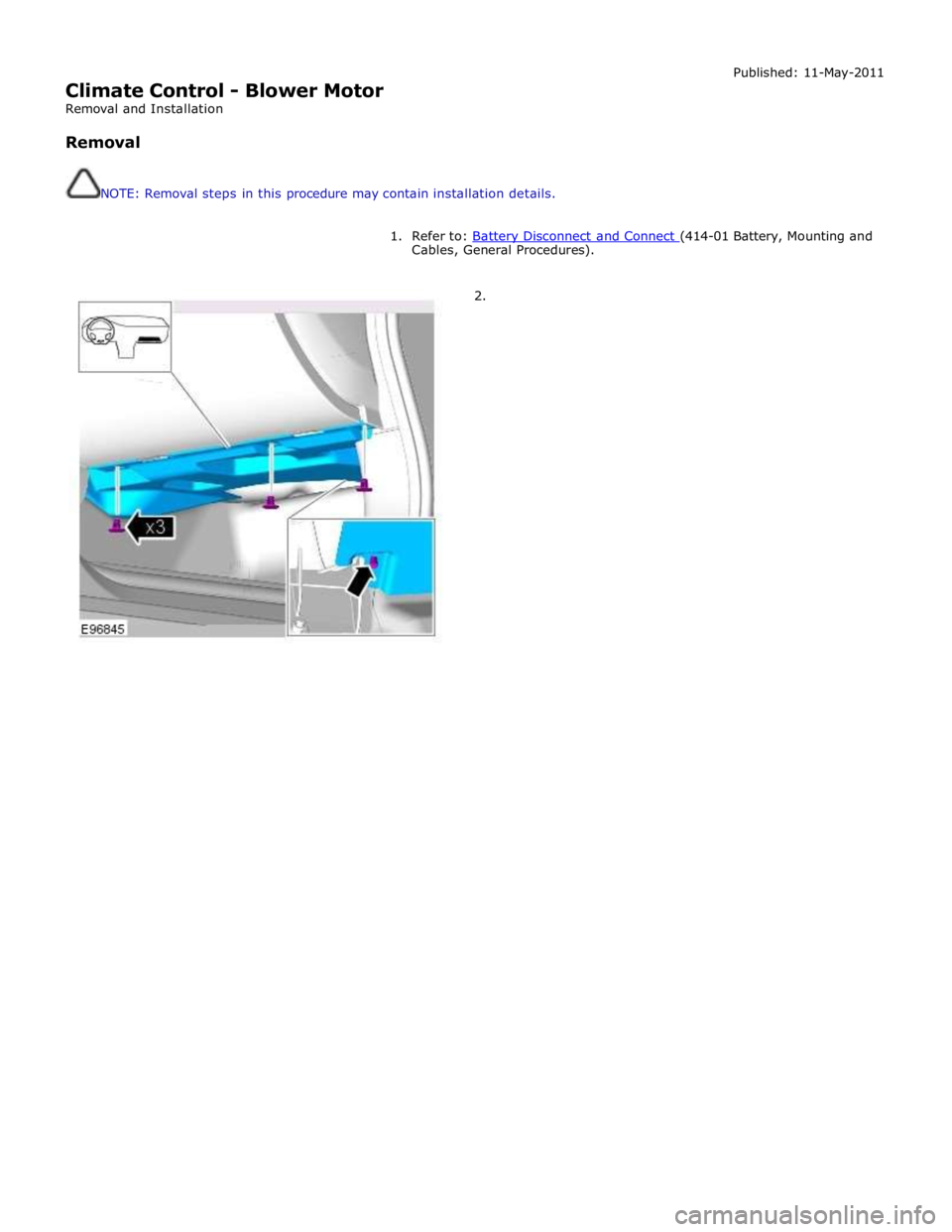
Climate Control - Blower Motor
Removal and Installation
Removal
NOTE: Removal steps in this procedure may contain installation details. Published: 11-May-2011
1. Refer to: Battery Disconnect and Connect (414-01 Battery, Mounting and Cables, General Procedures).
2.
Page 1721 of 3039

Climate Control - Blower Motor Control Module
Removal and Installation
Removal
NOTE: Removal steps in this procedure may contain installation details. Published: 11-May-2011
1. Refer to: Battery Disconnect and Connect (414-01 Battery, Mounting and Cables, General Procedures).
Installation
2. CAUTION: Take extra care not to damage the clips or
screw threads. Failure to follow this instruction may result
in damage to the climate control assembly.
NOTE: RHD illustration shown, LHD is similar.
3. Torque: 1.3 Nm
1. To install, reverse the removal procedure.
Page 1722 of 3039
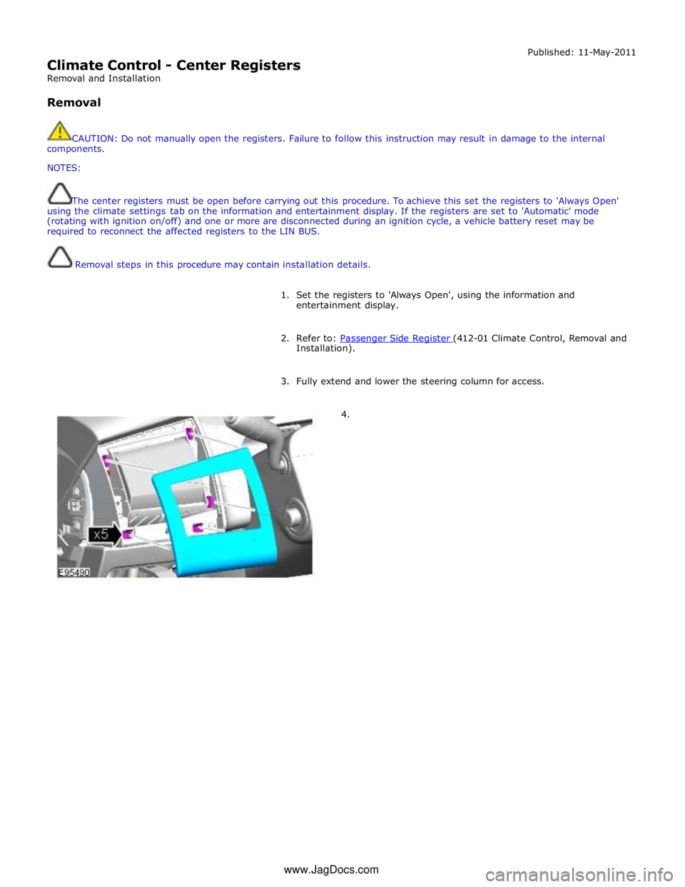
Climate Control - Center Registers
Removal and Installation
Removal Published: 11-May-2011
CAUTION: Do not manually open the registers. Failure to follow this instruction may result in damage to the internal
components.
NOTES:
The center registers must be open before carrying out this procedure. To achieve this set the registers to 'Always Open'
using the climate settings tab on the information and entertainment display. If the registers are set to 'Automatic' mode
(rotating with ignition on/off) and one or more are disconnected during an ignition cycle, a vehicle battery reset may be
required to reconnect the affected registers to the LIN BUS.
Removal steps in this procedure may contain installation details.
1. Set the registers to 'Always Open', using the information and
entertainment display.
2. Refer to: Passenger Side Register (412-01 Climate Control, Removal and Installation).
3. Fully extend and lower the steering column for access.
4. www.JagDocs.com
Page 1725 of 3039
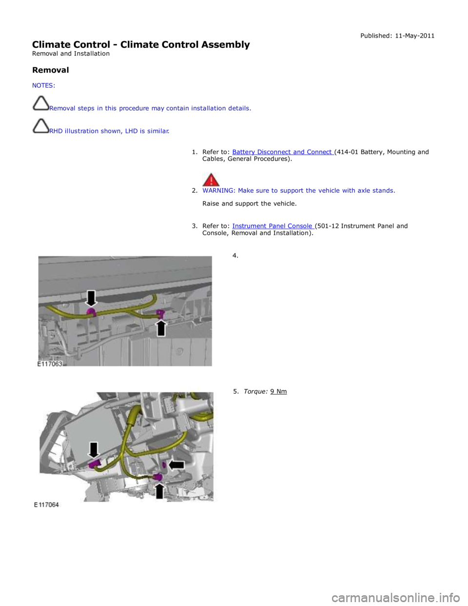
Climate Control - Climate Control Assembly
Removal and Installation
Removal
NOTES:
Removal steps in this procedure may contain installation details.
RHD illustration shown, LHD is similar. Published: 11-May-2011
1. Refer to: Battery Disconnect and Connect (414-01 Battery, Mounting and Cables, General Procedures).
2. WARNING: Make sure to support the vehicle with axle stands.
Raise and support the vehicle.
3. Refer to: Instrument Panel Console (501-12 Instrument Panel and Console, Removal and Installation).
4.
5. Torque: 9 Nm