JAGUAR XFR 2010 1.G Manual PDF
XFR 2010 1.G
JAGUAR
JAGUAR
https://www.carmanualsonline.info/img/21/7642/w960_7642-0.png
JAGUAR XFR 2010 1.G Manual PDF
Page 1751 of 3039
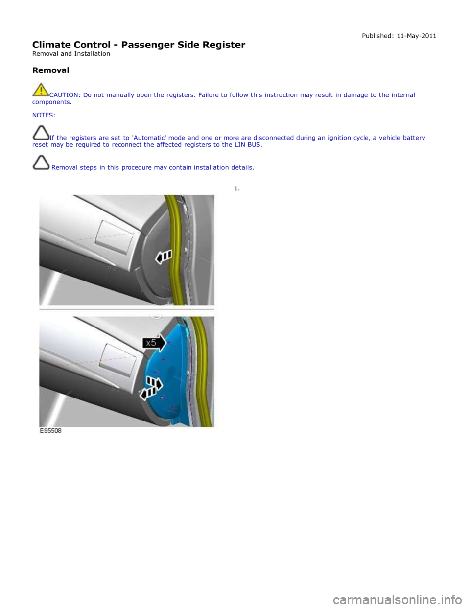
Climate Control - Passenger Side Register
Removal and Installation
Removal Published: 11-May-2011
CAUTION: Do not manually open the registers. Failure to follow this instruction may result in damage to the internal
components.
NOTES:
If the registers are set to 'Automatic' mode and one or more are disconnected during an ignition cycle, a vehicle battery
reset may be required to reconnect the affected registers to the LIN BUS.
Removal steps in this procedure may contain installation details.
1.
Page 1755 of 3039
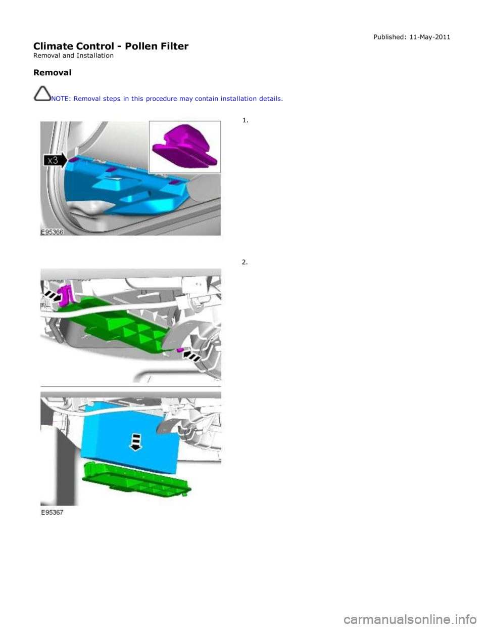
Climate Control - Pollen Filter
Removal and Installation
Removal
NOTE: Removal steps in this procedure may contain installation details.
1.
2. Published: 11-May-2011
Page 1757 of 3039
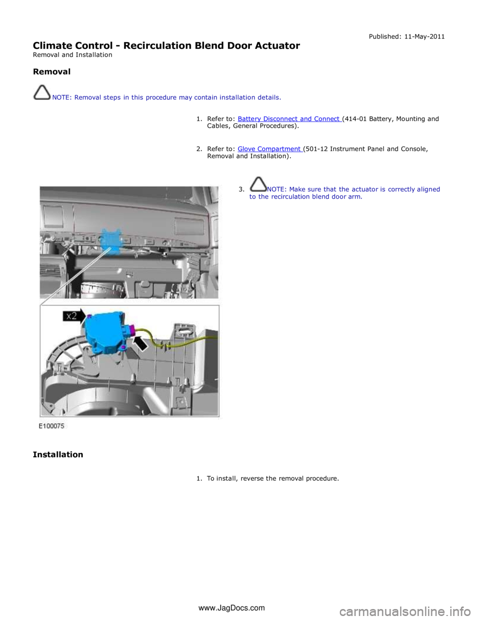
Climate Control - Recirculation Blend Door Actuator
Removal and Installation
Removal
NOTE: Removal steps in this procedure may contain installation details. Published: 11-May-2011
1. Refer to: Battery Disconnect and Connect (414-01 Battery, Mounting and Cables, General Procedures).
2. Refer to: Glove Compartment (501-12 Instrument Panel and Console, Removal and Installation).
Installation
3. NOTE: Make sure that the actuator is correctly aligned
to the recirculation blend door arm.
1. To install, reverse the removal procedure. www.JagDocs.com
Page 1758 of 3039
Climate Control - Sunload Sensor
Removal and Installation
Removal
NOTE: Removal steps in this procedure may contain installation details. Published: 11-May-2011
1. Refer to: Battery Disconnect and Connect (414-01 Battery, Mounting and Cables, General Procedures).
2. CAUTIONS:
Protect the surrounding trim to avoid damage.
Make sure that the clips are correctly located.
3.
4. CAUTION: Make sure that the component is correctly
located on the locating dowels.
Torque: 2 Nm
Page 1760 of 3039
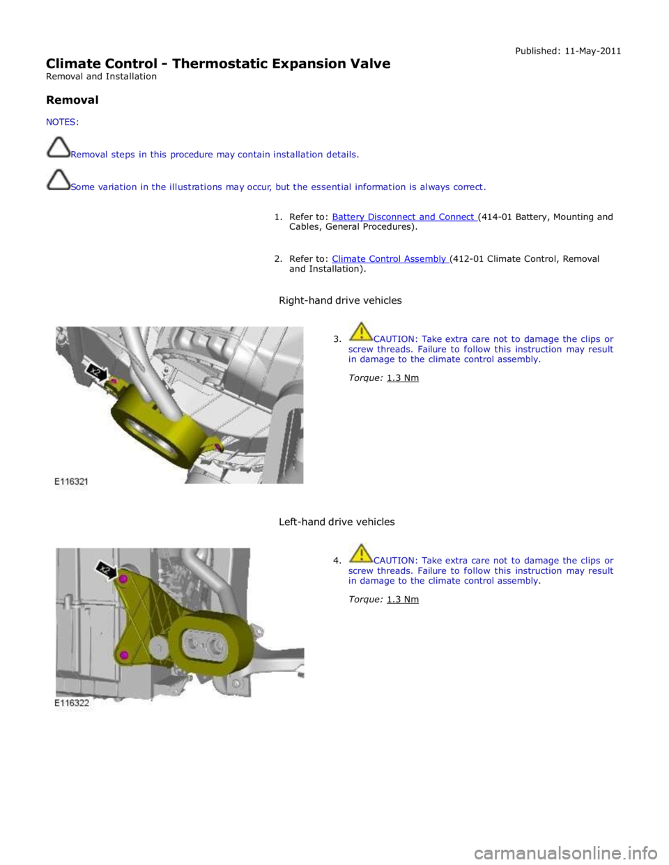
Climate Control - Thermostatic Expansion Valve
Removal and Installation
Removal
NOTES:
Removal steps in this procedure may contain installation details.
Some variation in the illustrations may occur, but the essential information is always correct. Published: 11-May-2011
1. Refer to: Battery Disconnect and Connect (414-01 Battery, Mounting and Cables, General Procedures).
2. Refer to: Climate Control Assembly (412-01 Climate Control, Removal and Installation).
Right-hand drive vehicles
3. CAUTION: Take extra care not to damage the clips or
screw threads. Failure to follow this instruction may result
in damage to the climate control assembly.
Torque: 1.3 Nm
Left-hand drive vehicles
4. CAUTION: Take extra care not to damage the clips or
screw threads. Failure to follow this instruction may result
in damage to the climate control assembly.
Torque: 1.3 Nm
Page 1762 of 3039
Published: 11-May-2011
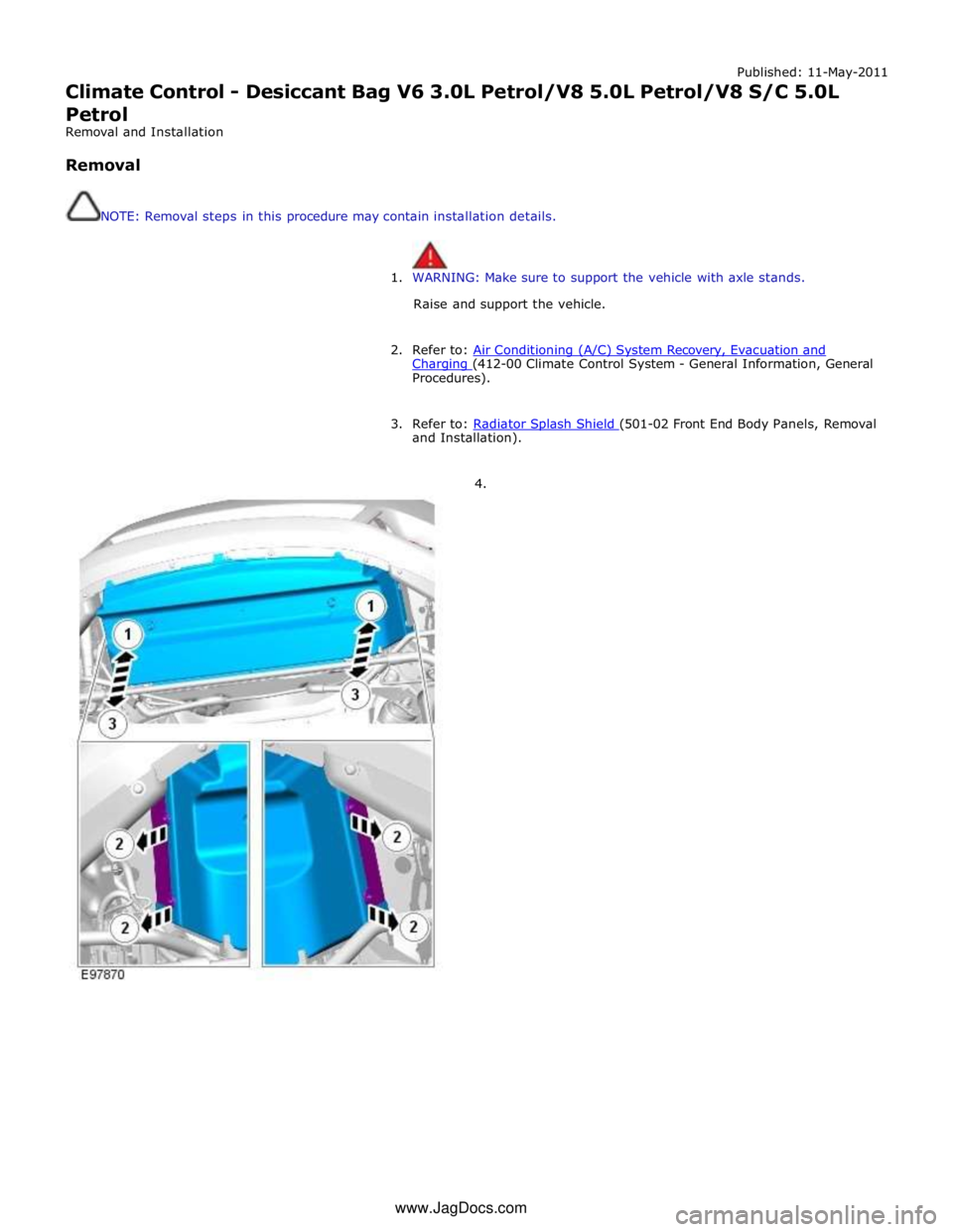
Climate Control - Desiccant Bag V6 3.0L Petrol/V8 5.0L Petrol/V8 S/C 5.0L
Petrol
Removal and Installation
Removal
NOTE: Removal steps in this procedure may contain installation details.
1. WARNING: Make sure to support the vehicle with axle stands.
Raise and support the vehicle.
2. Refer to: Air Conditioning (A/C) System Recovery, Evacuation and Charging (412-00 Climate Control System - General Information, General Procedures).
3. Refer to: Radiator Splash Shield (501-02 Front End Body Panels, Removal and Installation).
4. www.JagDocs.com
Page 1765 of 3039
Published: 11-May-2011
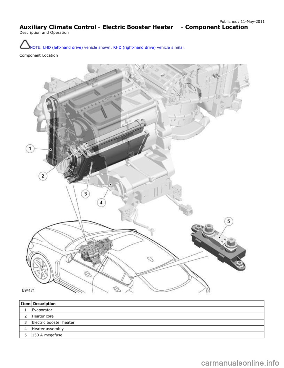
Auxiliary Climate Control - Electric Booster Heater - Component Location
Description and Operation
NOTE: LHD (left-hand drive) vehicle shown, RHD (right-hand drive) vehicle similar.
Component Location
Item Description 1 Evaporator 2 Heater core 3 Electric booster heater 4 Heater assembly 5 150 A megafuse
Page 1766 of 3039
Published: 11-May-2011
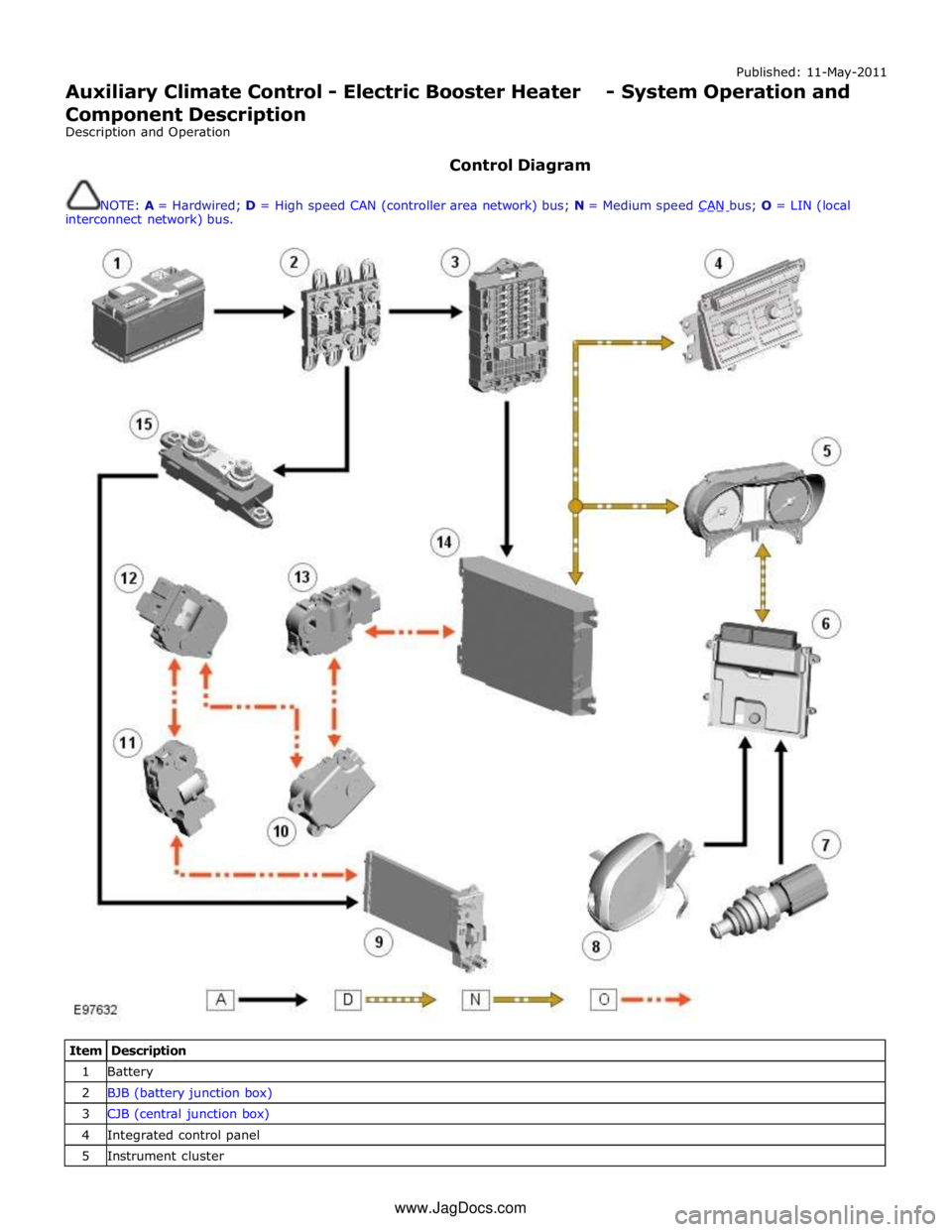
Auxiliary Climate Control - Electric Booster Heater - System Operation and
Component Description
Description and Operation
Control Diagram
NOTE: A = Hardwired; D = High speed CAN (controller area network) bus; N = Medium speed CAN bus; O = LIN (local interconnect network) bus.
Item Description 1 Battery 2 BJB (battery junction box) 3 CJB (central junction box) 4 Integrated control panel 5 Instrument cluster www.JagDocs.com
Page 1768 of 3039
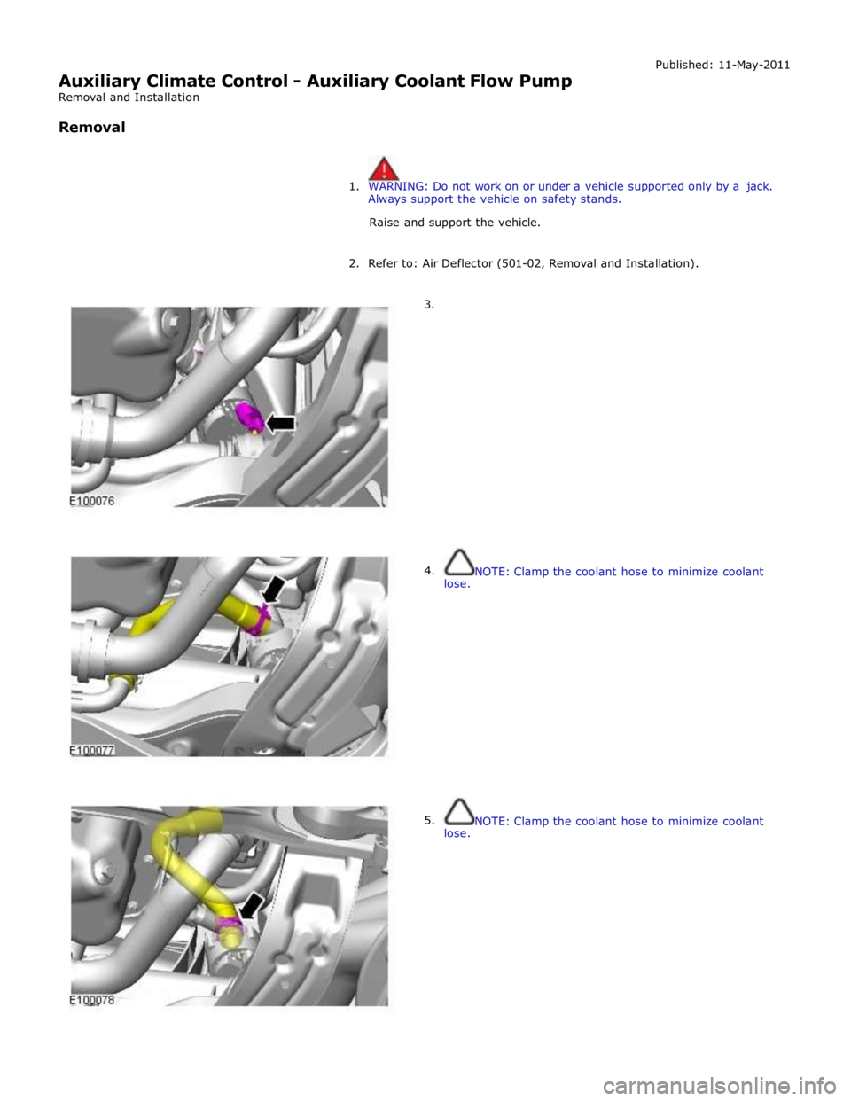
Auxiliary Climate Control - Auxiliary Coolant Flow Pump
Removal and Installation
Removal Published: 11-May-2011
1. WARNING: Do not work on or under a vehicle supported only by a jack.
Always support the vehicle on safety stands.
Raise and support the vehicle.
2. Refer to: Air Deflector (501-02, Removal and Installation).
3.
4.
lose.
5.
lose.
NOTE: Clamp the coolant hose to minimize coolant
NOTE: Clamp the coolant hose to minimize coolant
Page 1772 of 3039
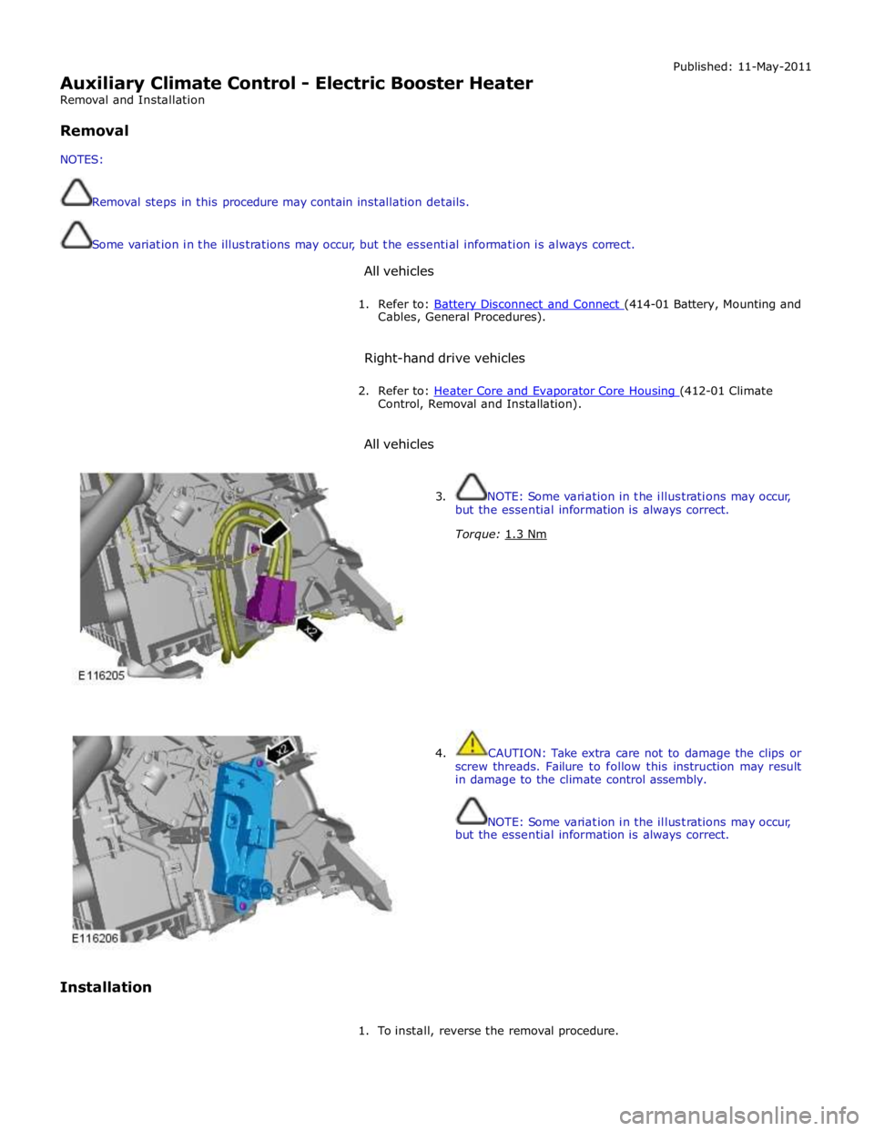
Auxiliary Climate Control - Electric Booster Heater
Removal and Installation
Removal
NOTES:
Removal steps in this procedure may contain installation details.
Some variation in the illustrations may occur, but the essential information is always correct.
All vehicles Published: 11-May-2011
1. Refer to: Battery Disconnect and Connect (414-01 Battery, Mounting and Cables, General Procedures).
Right-hand drive vehicles
2. Refer to: Heater Core and Evaporator Core Housing (412-01 Climate Control, Removal and Installation).
All vehicles
Installation
3. NOTE: Some variation in the illustrations may occur,
but the essential information is always correct.
Torque: 1.3 Nm
4. CAUTION: Take extra care not to damage the clips or
screw threads. Failure to follow this instruction may result
in damage to the climate control assembly.
NOTE: Some variation in the illustrations may occur,
but the essential information is always correct.
1. To install, reverse the removal procedure.
