instrument cluster JAGUAR XFR 2010 1.G Repair Manual
[x] Cancel search | Manufacturer: JAGUAR, Model Year: 2010, Model line: XFR, Model: JAGUAR XFR 2010 1.GPages: 3039, PDF Size: 58.49 MB
Page 779 of 3039
8 Reach adjustment solenoid and potentiometer 9 Column adjustment motor 10 Instrument cluster 11 Steering column adjust switch 12 Driver's seat module (position memory)
STEERING COLUMN ADJUSTMENT System Operation
Power for the column adjustment motor is supplied via a megafuse in the BJB to the CJB. A fused supply from the CJB is passed to the instrument cluster which controls the power application to the motor.
The column adjust switch is hardwired to the instrument cluster. Up/down and in/out selections on the switch are each passed
through a resistor of differing values to the instrument cluster. The cluster monitors the output value from the switch and
operates the motor in the required direction and simultaneously energizes the required solenoid for rake or reach adjustment.
When the applicable solenoid is energized, a clutch is engaged and locates on a lead screw. The motor rotates the lead screw
and the rotational drive of the screw is transferred into linear movement of the applicable clutch to move either the rake or
reach adjustment. For reach adjustment, the lead screw drives the outer housing in or out as required. For rake adjustment the
lead screw drives a rake lever which moves the column up or down as required.
The position of the column is monitored by potentiometers which are connected to the instrument cluster. The cluster monitors
the output signal from the potentiometers to precisely control the positioning of the column in each plane.
The instrument cluster controls the memory positioning of the column via a medium speed CAN bus connection to the driver's seat module. The driver's seat module receives information regarding the particular remote handset used to enter the vehicle
and outputs positional information relative to that stored for the handset. This information is passed to the instrument cluster
via the medium speed CAN bus which moves the column to the memorized positions.
The column logic in the instrument cluster also incorporates an entry/exit mode. When the vehicle is unlocked or the ignition is
switched off, the instrument cluster lifts the column upwards to its maximum rake position to allow the driver more room below
the steering wheel and improve access/egress of the vehicle. When the ignition is next switched on the column will adjust to
its previous position.
The electric steering column lock is controlled by the CJB.
Page 797 of 3039
Published: 11-May-2011
Steering Column Switches - Steering Column Switches - Overview
Description and Operation
OVERVIEW
The steering column multifunction switch is situated on the steering column and consists of the wiper switch, the turn signal
indicator/lighting switch and the trip computer switch.
The RH (right-hand) multifunction switch controls the following windshield wiper functions:
Flick wipe
Intermittent wipe
Slow speed wipe
High speed wipe
Wash/Wipe
Headlamp powerwash
Rain sensing / variable wipe selection.
The LH (left-hand) multifunction switch controls the following functions:
Turn signal indicators
Side lamps
Headlamps
Auto lamps
High/low beam
Headlamp flash
Headlamp timer
Trip computer.
The steering column adjustment switch is located in the steering column lower shroud on the LH side. The switch is a 4 position 'joystick' which controls reach and rake adjustment.
The trip button allows the driver to cycle though an option menu and also reset trip cycle mileage calculations. The trip
computer information is displayed in the instrument cluster message centre.
Steering wheel mounted switches on the LH side of the driver's airbag, control the audio and telephone functions. Switches on the RH side of the driver's airbag, control the speed control functions. The steering wheel has an internal heating element. This is controlled by the driver via the Touch Screen Display (TSD). www.JagDocs.com
Page 799 of 3039
8 Steering column LH (left-hand) multifunction switch 9 Steering column RH (right-hand) multifunction switch 10 Instrument cluster 11 Speed control switches 12 Audio/telephone switches 13 Clockspring 14 Information and entertainment module 15 Media Oriented System Transport (MOST) ring connection to other vehicle systems 16 Medium speed CAN (controller area network) bus to other vehicle systems
LEFT HAND MULTIFUNCTION SWITCH
Turn Signal Indicators System Operation
The instrument cluster outputs a reference voltage to the turn signal indicator switch. When the switch is in the central off
position, the voltage flows through 3 resistors which are connected in series and back to the instrument cluster which monitors
the signal and determines the turn signal indicators are off. This information is broadcast on the medium speed CAN bus to the CJB.
When the switch is operated in the LH turn signal indicator position, the reference voltage from the instrument cluster is routed via 1 of the resistors. The returned signal voltage is detected by the instrument cluster which outputs a message on
the medium speed CAN bus to the CJB. The CJB activates the applicable turn signal indicators until it receives an off message from the instrument cluster.
When the switch is operated in the RH turn signal indicator position, the reference voltage from the instrument cluster is routed via 2 of the resistors. The returned signal voltage is detected by the instrument cluster which outputs a message on
the medium speed CAN bus to the CJB. The CJB activates the applicable turn signal indicators until it receives an off message from the instrument cluster.
Lighting Control Switch
The instrument cluster outputs 2 reference voltages to the rotary lighting control switch; one feed being supplied to the light
selection function of the switch and the second feed being supplied to the autolamp exit delay function. The switch position is
determined by instrument cluster by the change in returned signal voltage which is routed through up to 4 resistors in series
depending on the selection made.
When the lighting control switch is in the off position, the reference voltage flows through 1 of the resistors. The returned
signal voltage is detected by the instrument cluster which outputs a message on the medium speed CAN bus to the CJB that no lighting selection is made. The reference voltage to the autolamp exit delay switch is routed through 4 resistors which is
detected by the instrument cluster which outputs a message on the medium speed CAN bus to the CJB that autolamp or exit delay has not been selected.
When the lighting control switch is in the sidelamp position, the reference voltage flows through 2 of the resistors. The
returned signal voltage is detected by the instrument cluster which outputs a message on the medium speed CAN bus to the CJB to activate the sidelamps. The reference voltage to the autolamp exit delay switch is routed through 4 resistors which is detected by the instrument cluster which outputs a message on the medium speed CAN bus to the CJB that autolamp or exit delay has not been selected.
When the lighting control switch is in the headlamp position, the reference voltage flows through 3 of the resistors. The
returned signal voltage is detected by the instrument cluster which outputs a message on the medium speed CAN bus to the CJB to activate the headlamps. The reference voltage to the autolamp exit delay switch is routed through 4 resistors which is detected by the instrument cluster which outputs a message on the medium speed CAN bus to the CJB that autolamp or exit delay has not been selected.
When the lighting control switch is in the autolamp position, the reference voltage flows through 4 of the resistors. The
returned signal voltage is detected by the instrument cluster which outputs a message on the medium speed CAN bus to the CJB to activate the autolamp function. The reference voltage to the autolamp exit delay switch is routed through 4 resistors which is detected by the instrument cluster which outputs a message on the medium speed CAN bus to the CJB that autolamp has been selected.
Autolamp Exit Delay
When the lighting control switch is in any of the autolamp exit delay position, the lighting control switch reference voltage
flows through 4 of the resistors. The returned signal voltage is detected by the instrument cluster which outputs a message on
the medium speed CAN bus to the CJB that autolamps has been selected.
Depending on the selected position, the reference voltage to the autolamp exit delay switch is routed through 3, 2 or 1
resistors which is detected by the instrument cluster. The cluster outputs a message on the medium speed CAN bus to the CJB that autolamp exit delay period has been selected at 30, 60 or 120 seconds respectively.
Trip Function Button
The instrument cluster outputs a reference voltage to the trip function button. When the function button is pressed a ground
Page 800 of 3039
path is completed and a signal voltage is returned to the instrument cluster via a resistor. The returned reference voltage is
detected by the instrument cluster and performs the requested trip function.
RIGHT HAND MULTIFUNCTION SWITCH
The instrument cluster outputs 4 separate reference voltages to the following switch functions:
Wash/wipe switch
Intermittent wipe switch
Master wiper switch
Flick wipe switch.
Wash/Wipe Switch
The reference voltage is supplied to one of two resistors connected in parallel. When the switch is not being operated the
current flows through one resistor and the returned signal voltage is monitored by the instrument cluster. When the wash/wipe
switch is operated, a connection is made and the current flows through the second resistor. The change in signal voltage is
detected by the instrument cluster which outputs a message on the medium speed CAN bus to the CJB to activate the wash/wipe function.
Intermittent Delay/Auto Wipe Switch
The reference voltage is supplied to the switch and can pass through up to 7 resistors, connected in series, for intermittent
delay selections and the auto wipe function.
When the rotary switch is in the auto position the reference voltage flows through 1 resistor. The returned signal voltage is
detected by the instrument cluster which determines auto wipe is selected. The instrument cluster outputs a message on the
medium speed CAN bus to the CJB to activate the auto wipe function.
With the rotary switch in one of the intermittent positions, the reference voltage is routed through up to 7 of the resistors
depending on the delay period selected. The returned signal voltage is detected by the instrument cluster which determines
selected delay period. The instrument cluster outputs a message on the medium speed CAN bus to the CJB to activate the selected intermittent wipe function.
NOTE: The delay period for the intermittent selections can vary according to vehicle speed.
Master Wiper Switch
The reference voltage supplied from the instrument cluster to the master wiper switch. The voltage can pass through up to 4
resistors connected in series.
When the switch is in the off position, the reference voltage passes through 4 resistors and the returned voltage is monitored
by the instrument cluster. The instrument cluster outputs a message on the medium speed CAN bus to the CJB that no wiper selections have been requested.
With the switch in the intermittent, slow wipe or fast wipe position, the reference voltage passes through 3, 2 or 1 resistors
respectively. The returned signal voltage is detected by the instrument cluster which determines selected delay period. The
instrument cluster outputs a message on the medium speed CAN bus to the CJB to activate the selected wipe function. Flick Wipe Switch
The reference voltage is supplied to one of two resistors connected in parallel. When the switch is not being operated the
current flows through one resistor and the returned signal voltage is monitored by the instrument cluster. When the flick wipe
switch is operated, a connection is made and the current flows through the second resistor. The change in signal voltage is
detected by the instrument cluster which outputs a message on the medium speed CAN bus to the CJB to activate the flick wipe function.
STEERING COLUMN ADJUSTMENT SWITCH
The instrument cluster supplies 2 reference voltages to the column adjustment switch.
The first reference voltage is supplied to the joystick switch. When the switch is moved to one of its 4 positions, the switch
contact is completed and the reference voltage is passed through one of 4 different resistors with different values. The
returned signal voltage is measured by the instrument cluster which determines the selected column adjust request. The
instrument cluster outputs a supply to the steering column adjustment motor and energizes the applicable clutch solenoid to
move the column to the desired position.
The second reference voltage is supplied to the auto/manual selection of the switch. When the switch is in the auto position,
the reference voltage passes directly through the switch contacts and is measured by the instrument cluster. The instrument
cluster outputs a message on the medium speed CAN bus to the driver seat module which responds with the recorded memory position setting. The instrument cluster then activates the column adjustment motor and clutch solenoids to move the column
to the memorized position. When the switch is in the manual position the reference circuit is broken. The instrument cluster
detects the broken circuit and allows manual operation of the column adjustment switch to move the column.
HEATED STEERING WHEEL
The heated steering wheel receives a battery power supply via the CJB. The heated steering wheel is controlled by the driver using a selection on the TSD. When the driver selects the heated steering wheel to be active, the request is passed from the
TSD on the MOST ring to the information and entertainment module. The information and entertainment module converts the
Page 868 of 3039
cooling jets and the timing chain lubrication jets.
The oil returns to the oil pan under gravity. Large drain holes through the cylinder heads and cylinder block ensure the rapid
return of the oil to the sump pan. System replenishment is through the oil filler cap on the LH cylinder head cover.
An oil evacuation tube is installed to allow oil to be drawn from the sump pan. The upper end of the oil evacuation tube is
located under the oil filler cap.
An oil drain plug is installed in the RH side of the sump pan.
Oil Pump Nominal Operating Pressures
Engine Speed, rev/min Temperature, °C (°F) Pressure, bar (lbf/in2
) Idle 20 (68) 2.0 (29.0) 1500 20 (68) 6.0 (87.0) 3000 40 (104) 6.2 (90.0) 3000 110 (230) 5.0 (72.5) 3000 130 (266) 4.0 (58.0) Oil Level Monitoring
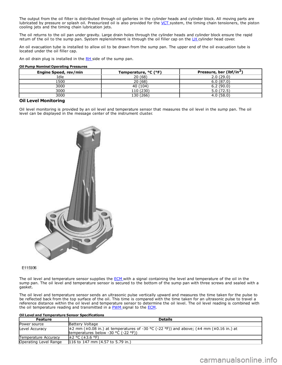
Oil level monitoring is provided by an oil level and temperature sensor that measures the oil level in the sump pan. The oil
level can be displayed in the message center of the instrument cluster.
The oil level and temperature sensor supplies the ECM with a signal containing the level and temperature of the oil in the sump pan. The oil level and temperature sensor is secured to the bottom of the sump pan with three screws and sealed with a
gasket.
The oil level and temperature sensor sends an ultrasonic pulse vertically upward and measures the time taken for the pulse to
be reflected back from the top surface of the oil. This time is compared with the time taken for an ultrasonic pulse to travel a
reference distance within the oil level and temperature sensor to determine the oil level. The oil level reading is combined with
the oil temperature reading and transmitted in a PWM signal to the ECM.
Oil Level and Temperature Sensor Specifications
Feature Details Power source Battery Voltage Level Accuracy ±2 mm (±0.08 in.) at temperatures of -30 °C (-22 °F)) and above; (±4 mm (±0.16 in.) at
temperatures below -30 °C (-22 °F)) Temperature Accuracy ±2 °C (±3.6 °F) Operating Level Range 116 to 147 mm (4.57 to 5.79 in.)
Page 1114 of 3039
14 Radiator 15 Auxiliary radiator 16 Connection with supercharger cooling system
System Operation
When the engine is running, the coolant is circulated around the engine cooling system by the coolant pump. From the coolant
pump, coolant flows through the cylinder heads and the engine oil cooler into the cylinder block and the heater manifold.
In the cylinder block, the coolant flows forwards to the outlet tube. When the coolant is cold, the thermostat is closed and the
coolant flows direct from the outlet tube back to the coolant pump. Once the coolant reaches operating temperature the
thermostat begins to open, to control system temperature, and coolant flows from the outlet tube to the coolant pump via the
radiator and, on SC (supercharger) vehicles, the auxiliary radiator. When the thermostat is open, the coolant flow through the
radiator(s) also generates a coolant flow through the transmission fluid cooler.
From the heater manifold the coolant flows through the electronic throttle and the heater core, in parallel circuits that are
unaffected by the position of the thermostat. From the electronic throttle, the coolant merges with bleed coolant from the
coolant pump and the outlet tube and flows to the expansion tank. From the heater core, the coolant flows back to the inlet of
the coolant pump.
Expansion and contraction of the coolant is accommodated by an air space in the expansion tank and the compliance of the
flexible hoses.
If the coolant level in the expansion tank decreases below a predetermined value, the level sensor connects a ground to the
instrument cluster, which activates the appropriate warning. For additional information, refer to 413-01 Instrument Cluster.
The cooling fan is operated by a fan control module integrated into the cooling fan motor. The fan control module regulates the
voltage, and thus speed, of the cooling fan motor in response to a PWM (pulse width modulation) signal from the ECM (engine
control module).
The cooling fan receives a battery feed and an ignition feed from the EJB (engine junction box). The ignition feed is supplied
from the main relay in the EJB, which is controlled by the ECM.
The ECM calculates the required fan speed from the engine temperature, A/C (air conditioning) system pressure and transmission fluid temperature. Under hot operating conditions, the fan may continue to operate for 4 minutes after the engine
has been switched off.
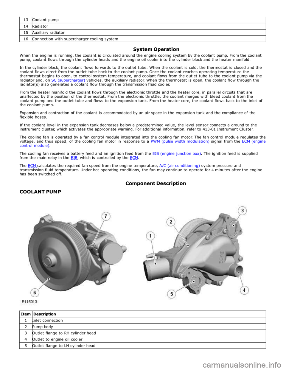
COOLANT PUMP Component Description
Item Description 1 Inlet connection 2 Pump body 3 Outlet flange to RH cylinder head 4 Outlet to engine oil cooler 5 Outlet flange to LH cylinder head
Page 1344 of 3039
Published: 11-May-2011
Evaporative Emissions - V8 5.0L Petrol/V8 S/C 5.0L Petrol - Evaporative Emissions - System Operation and Component Description
Description and Operation
System Operation DIAGNOSTIC MODULE - TANK LEAKAGE PUMP (NAS ONLY)
To check the fuel tank and the EVAP (evaporative emission) system for leaks, the ECM (engine control module) operates the
DMTL pump and monitors the current draw. Initially, the ECM establishes a reference current by pumping air through the reference orifice and back to atmosphere. Once the reference current is determined, the ECM closes the change-over valve, which seals the EVAP system. The EVAP canister purge valve remains de-energized and is therefore closed. The output from the air pump is diverted from the reference orifice and into the EVAP system.
When the change-over valve is closed, the load on the air pump falls to zero. Providing there are no leaks, the air pump will
begin to pressurize the EVAP system and the load and current draw in the pump increases. By monitoring the rate and level of the current increase, the ECM can determine if there is a leak in the EVAP system.
During normal vehicle operation, 15 seconds after the engine has started, the ECM energizes the heating element in the pump to prevent condensation formation and possible incorrect readings. The heater remains energized until either the engine and
ignition are off (if no DMTL test is running) or until after the DMTL test is completed.
Leaks are classified as:
Minor - equivalent to a hole diameter of 0.5 to 1.0 mm (0.02 to 0.04 in.).
Major - equivalent to a hole diameter of 1.0 mm (0.04 in.) or greater.
The ECM performs a check for major leaks each time the ignition is switched off, providing the following conditions are met: The vehicle speed is zero.
The engine speed is zero.
The atmospheric pressure is above 70 kPa (10.15 lbf/in2
), i.e. the altitude is less than approximately 3047 m (10000
feet).
The ambient temperature is between 0 and 40 °C (32 and 104 °F).
The EVAP canister vapor concentration factor is 5 or less (where 0 is no fuel vapor, 1 is stoichiometric fuel vapor and greater than 1 is rich fuel vapor).
The fuel tank level is valid and between 15 and 85% of nominal capacity.
The engine running time during the previous cycle was more than 10 minutes.
The battery voltage is between 10 and 15 volts.
The last engine off time was more than 180 minutes.
No errors are detected with the EVAP components, the ambient air temperature and the fuel level.
NOTE: A leak test can be performed using a Jaguar recognized diagnostic tool. This overrides the above conditions and is
useful for checking correct system and component operation.
The ECM performs a check for minor leaks after every 2nd major leak check.
When the leak check is complete, the ECM stops the DMTL pump and opens (de-energizes) the change-over valve.
If the fuel filler cap is opened or refueling is detected during the leak check, by a sudden drop in the current draw or a rise in
the fuel level, the ECM aborts the leak check.
If a leak is detected during the check, the ECM stores an appropriate fault code in its memory. If a leak is detected on two consecutive checks, the ECM illuminates the MIL (malfunction indicator lamp) in the instrument cluster on the next drive cycle. The duration of a leak check can be between 60 and 900 seconds depending on the results and fuel tank level.
EVAP CANISTER PURGE VALVE
The ECM waits until the engine is running above 55 °C (131 °F) coolant temperature with closed loop fuel operational before the purging process is activated. Under these conditions the engine should be running smoothly with no warm up enrichment.
The EVAP canister purge valve duty (and flow) is initially ramped slowly because the vapor concentration is unknown (a sudden increase in purge could cause unstable engine running or cause it to stall due to an extremely "rich" air/fuel mixture). The
concentration is then determined from the amount of adjustment that the closed loop fueling is required to make to achieve
the target AFR (air fuel ratio). Once the concentration has been determined, the purge flow can be increased rapidly and the
injected fuel can be pro-actively adjusted to compensate for the known purge vapor and the target AIR control is maintained.
When the purging process is active, fresh air is drawn into the EVAP canister via the DMTL filter and pump on NAS vehicles, or via the vent port on the EVAP canister of non NAS vehicles.
Page 1412 of 3039

TCM (transmission control module) 6 Diagnostic socket 7 Instrument cluster 8 JaguarDrive selector 9 Clockspring 10 Steering wheel audio switches 11 Downshift paddle switch 12 Upshift paddle switch 13 ECM (engine control module)
POWER FLOWS System Operation
Operation of the transmission is controlled by the TCM (transmission control module), which electrically activates various
solenoids to control the transmission gear selection. The sequence of solenoid activation is based on programmed information
in the TCM memory and physical transmission operating conditions such as vehicle speed, throttle position, engine load and JaguarDrive selector position.
Item Description 1 Torque input from engine 2 Torque converter lock-up clutch 3 Single web planetary gear carrier 4 Single web planetary gears 5 Single web sunwheel 1 6 Double web sunwheel 2 7 Double web planetary gears - long 8 Double web planetary gear carrier 9 Double web planetary gears - short 10 Double web sunwheel 3 11 Torque output from transmission A Multiplate clutch B Multiplate clutch C Multiplate brake D Multiplate brake E Multiplate clutch Engine torque is transferred, via operation of single or combinations of clutches to the 2 planetary gear trains. Both gear trains
are controlled by reactionary inputs from brake clutches to produce the 6 forward gears and 1 reverse gear. The ratios are as
follows: www.JagDocs.com
Page 1421 of 3039
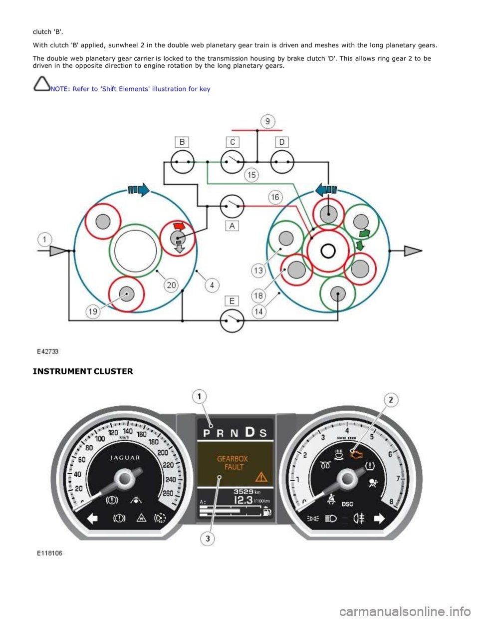
clutch 'B'.
With clutch 'B' applied, sunwheel 2 in the double web planetary gear train is driven and meshes with the long planetary gears.
The double web planetary gear carrier is locked to the transmission housing by brake clutch 'D'. This allows ring gear 2 to be
driven in the opposite direction to engine rotation by the long planetary gears.
NOTE: Refer to 'Shift Elements' illustration for key
INSTRUMENT CLUSTER
Page 1422 of 3039
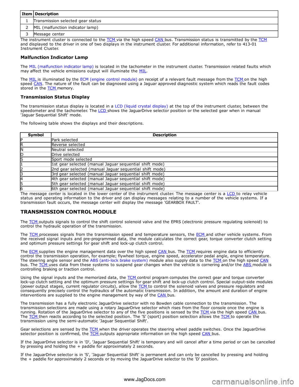
1 Transmission selected gear status 2 MIL (malfunction indicator lamp) 3 Message center The instrument cluster is connected to the TCM via the high speed CAN bus. Transmission status is transmitted by the TCM and displayed to the driver in one of two displays in the instrument cluster. For additional information, refer to 413-01
Instrument Cluster.
Malfunction Indicator Lamp
The MIL (malfunction indicator lamp) is located in the tachometer in the instrument cluster. Transmission related faults which
may affect the vehicle emissions output will illuminate the MIL.
The MIL is illuminated by the ECM (engine control module) on receipt of a relevant fault message from the TCM on the high speed CAN. The nature of the fault can be diagnosed using a Jaguar approved diagnostic system which reads the fault codes stored in the TCM memory.
Transmission Status Display
The transmission status display is located in a LCD (liquid crystal display) at the top of the instrument cluster, between the
speedometer and the tachometer. The LCD shows the JaguarDrive selector position or the selected gear when in manual 'Jaguar Sequential Shift' mode.
The following table shows the displays and their descriptions.
Symbol Description P Park selected R Reverse selected N Neutral selected D Drive selected S Sport mode selected 1 1st gear selected (manual Jaguar sequential shift mode) 2 2nd gear selected (manual Jaguar sequential shift mode) 3 3rd gear selected (manual Jaguar sequential shift mode) 4 4th gear selected (manual Jaguar sequential shift mode) 5 5th gear selected (manual Jaguar sequential shift mode) 6 6th gear selected (manual Jaguar sequential shift mode) The message center is located in the lower center of the instrument cluster. The message center is a LCD to relay vehicle status and operating information to the driver and can display messages relating to a number of the vehicle systems. If a
transmission fault occurs, the message center will display the message 'GEARBOX FAULT'.
TRANSMISSION CONTROL MODULE
The TCM outputs signals to control the shift control solenoid valve and the EPRS (electronic pressure regulating solenoid) to control the hydraulic operation of the transmission.
The TCM processes signals from the transmission speed and temperature sensors, the ECM and other vehicle systems. From the received signal inputs and pre-programmed data, the module calculates the correct gear, torque converter clutch setting
and optimum pressure settings for gear shift and lock-up clutch control.
The ECM supplies the engine management data over the high speed CAN bus. The TCM requires engine data to efficiently control the transmission operation, for example; flywheel torque, engine speed, accelerator pedal angle, engine temperature.
The steering angle sensor and the ABS (anti-lock brake system) module also supply data to the TCM on the high speed CAN bus. The TCM uses data from these systems to suspend gear changes when the vehicle is cornering and/or the ABS module is controlling braking or traction control.
Using the signal inputs and the memorized data, the TCM control program computes the correct gear and torque converter lock-up clutch setting and the optimum pressure settings for gear shift and lock-up clutch control. Special output-side modules
(power output stages, current regulator circuits), allow the TCM to control the solenoid valves and pressure regulators and consequently precisely control the hydraulics of the automatic transmission. In addition, the amount and duration of engine
interventions are supplied to the engine management by way of the CAN bus.
The transmission has a fully electronic JaguarDrive selector with no Bowden cable connection to the transmission. The
transmission selections are made using a rotary JaguarDrive selector which rises from the floor console once the engine is
running. Rotation of the JaguarDrive selector to any of the five positions is sensed by the TCM via the high speed CAN bus. The TCM then reacts according to the selected position. The 'S' (sport) position selection allows the TCM to operate the transmission using the semi-automatic 'Jaguar Sequential Shift'.
Gear selections are sensed by the TCM when the driver operates the steering wheel paddle switches. Once the JaguarDrive selector position is confirmed, the TCM outputs appropriate information on the high speed CAN bus.
If the JaguarDrive selector is in 'D', 'Jaguar Sequential Shift' is temporary and will cancel after a time period or can be cancelled
by pressing and holding the + paddle for approximately 2 seconds.
If the JaguarDrive selector is in 'S', 'Jaguar Sequential Shift' is permanent and can only be cancelled by pressing and holding
the + paddle for approximately 2 seconds or by moving the JaguarDrive selector to the 'D' position.
www.JagDocs.com