window JAGUAR XFR 2010 1.G Manual Online
[x] Cancel search | Manufacturer: JAGUAR, Model Year: 2010, Model line: XFR, Model: JAGUAR XFR 2010 1.GPages: 3039, PDF Size: 58.49 MB
Page 2733 of 3039
- Air flow checker
- Sealing compound (tape and plastic compound)
- Multi-purpose sticker
- Clinched flange sealer
- Window sealing compound
- Water shield (PVC)
- Double-sided adhesive tape for water shield
- Methylated spirit (available from trade outlets)
- PU adhesive
- Silicone remover
- Tar remover
Water leaks according to mileage or running time
Increasing mileage has an effect on the problem of leaks in a vehicle. Possible influencing factors are:
Servicing and maintenance of seals:
- No maintenance, lack of maintenance or incorrect maintenance
- Using an incorrect agent
Damaged seals:
- As a result of aging, wear or incorrect handling/assembly.
Heavy soiling of the vehicle:
- Heavy soiling of a vehicle can seriously impair the function of water drainage channels in particular, and also of
rubber seals.
Age-related factors:
- Environmental factors
- UV radiation
- Extreme climatic conditions
Corrosion can have a serious impact on bodywork, in particular as a result of:
- Lightly or heavily rusted seal carriers
- Rusted body seal welds
- Perforation corrosion
Water leaks after body repairs
If a vehicle develops a leak after body repairs, the following points must be taken into consideration in particular:
The correct seating of ancillary components and their seals must be checked.
The correct alignment of doors/tailgate and liftgate must be checked. The associated seals must not be damaged and
must be installed correctly.
Check that panel seams are correctly sealed.
The correct seating of rubber grommets must be checked.
Directly-glazed windows must have correct and complete bonding.
Water drainage system
If a vehicle develops water leaks, then areas into which water is routed or drained should be checked first.
Page 2735 of 3039

Side windows
In the case of side windows, the same problems can arise as for a windscreen. The same corrective actions must therefore be
used.
Door seal
Diagnosis:
- Water ingress in the lower part of the interior door trim or in the rocker panel area.
Cause:
- The water shield fitted behind the interior door trim exists to drain off water that has entered the door via the
drainage holes, either downwards or outwards. If the water shield seal is damaged or has been fitted incorrectly,
then water can get into the passenger compartment.
- In addition to this, the drainage holes can become clogged with leaves, dirt or excess cavity protection agents.
Water gathers in the door and ingresses into the passenger compartment.
- Check water shield for damage or correct fitting.
- If the water shield needs to be re-bonded, then approved seam sealer should be used.
- Before the water shield is installed, the drainage holes must be checked for unhindered flow.
Door seals
Diagnosis:
- Ingress of water into the rocker panel area
Cause:
- Insufficient clamping load between seal and door.
Corrective action:
NOTE: When adjusting the clamping load, the profile alignment of the relevant components must always be taken
into consideration.
NOTE: Do not realign the flange too far in the direction of the door, as this can reduce the bearing surface of the
seal to the door.
- Check clamping load:
- The easiest way to check the clamping load of a seal to the respective bearing surface is by means of a paper
strip test. This consists of trapping strips of paper at various points between the door and the seal, and fully
closing the door. If it is possible to pull out the paper with no great resistance, then the clamping load is too
low.
- Adjust the clamping load:
- The clamping load is normally adjusted using the striker. When doing so, the edge alignment from the door to
the side panel, or from the front door to the rear door must be taken into account.
- Another setting method is to realign the panel flange for the seal mounting. The clamping load is increased by
moving the flange towards the door.
- Check the bearing surface:
- Apply chalk evenly to the surface of the seal. Evenly coat the bearing surface of the door with Vaseline.
- Close the door fully, the lock must engage. Open the door. The imprint of the chalk (bearing surface) can be
identified in the film of Vaseline.
- The bearing surface should be at least 5mm across at all points.
Other causes:
- The door seal must completely seal the door where it meets the bodywork.
- Water can ingress directly or indirectly into the interior of the vehicle if the seal is damaged at any point.
Corrective action:
- A damaged or worn door seal must always be renewed in full.
- When renewing the seal, the following must be taken into account:
- Always fit the seal first in the area of the narrow radii (corner points).
- Next, secure the seal to the flange evenly by tapping lightly with a rubber hammer. The installed seal must not
be kinked at any point.
NOTE: The prescribed length of a seal must not be shortened.
Other cause:
- The door seal is attached to the welded flange all the way round. If this welded flange is uneven or damaged at
any point (usually in areas with small radii) then this point could be subject to leaks.
- A stretched seal carrier can also cause a leak.
- In both cases, water gets into the vehicle interior under the seal carrier.
Corrective action:
- Align the deformed welded flange using a hammer and anvil block, prevent and, if necessary, repair any paint
damage.
Sliding roof/tilting roof
Diagnosis:
- Ingress of water at sliding roof aperture
Cause:
- The sliding roof/tilting roof is installed in a water trap. The water drains off via the water trap, water drain holes
and drain hoses. The drain hoses lead downwards on both sides via the A-pillar and B-pillar.
- The drain holes or drain hoses can become clogged with leaves, dirt, underbody protection and so on.
Corrective action:
Page 2736 of 3039

NOTE: In the case of a sliding or tilting roof, the external rubber seal and the lock actuator or latch mechanism
must be checked first of all.
- Check the water trap for leaks.
- Check the drain hoses for leaks and for correct connection to the water trap.
- Check the drainage system for unhindered flow, and blow out with compressed air if necessary.
- Check the external seal and the correct adjustment of the sliding roof.
Liftgate
Diagnosis:
- Ingress of water into rear headlining area and luggage area.
Cause:
- The leak problems of the tailgate and liftgate correspond to those of the doors.
- In addition to this, the area to be sealed is much bigger. The routing holes for cables and hoses must also be
sealed.
- The rubber grommets for the routing holes must be checked for damage and correct seating (fully unhooked).
- The mounting points of the liftgate hinges may leak.
Corrective action:
- Check the rubber grommets and renew if necessary.
- Check the hinge mounting points, and re-seal with sealing compound if necessary.
Forced air extraction
Diagnosis:
- Ingress of water into side luggage compartment area
Cause:
- The forced air extraction for the vehicle interior is located in the quarter panel lower extension.
- The rubber flap of the forced air extraction must be able to move freely.
Corrective action:
- Remove the forced air extraction.
- Check the seal area between the bodywork and housing, as well as the rubber flap.
- Renew seal if necessary.
Rear window
Diagnosis:
- Ingress of water into the luggage compartment area
Cause:
- Rear window leaking.
- Check for leak in the same way as for leaking windscreen.
Page 2751 of 3039
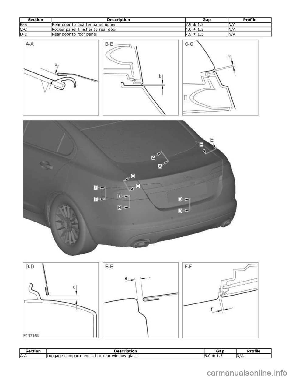
B-B Rear door to quarter panel upper 7.9 ± 1.5 N/A C-C Rocker panel finisher to rear door 4.0 ± 1.5 N/A D-D Rear door to roof panel 7.9 ± 1.5 N/A
Section Description Gap Profile A-A Luggage compartment lid to rear window glass 6.0 ± 1.5 N/A
Page 2828 of 3039
Published: 11-May-2011
Roof Sheet Metal Repairs - Roof Panel Vehicles With: Sliding Roof Opening
Panel
Removal and Installation
Removal
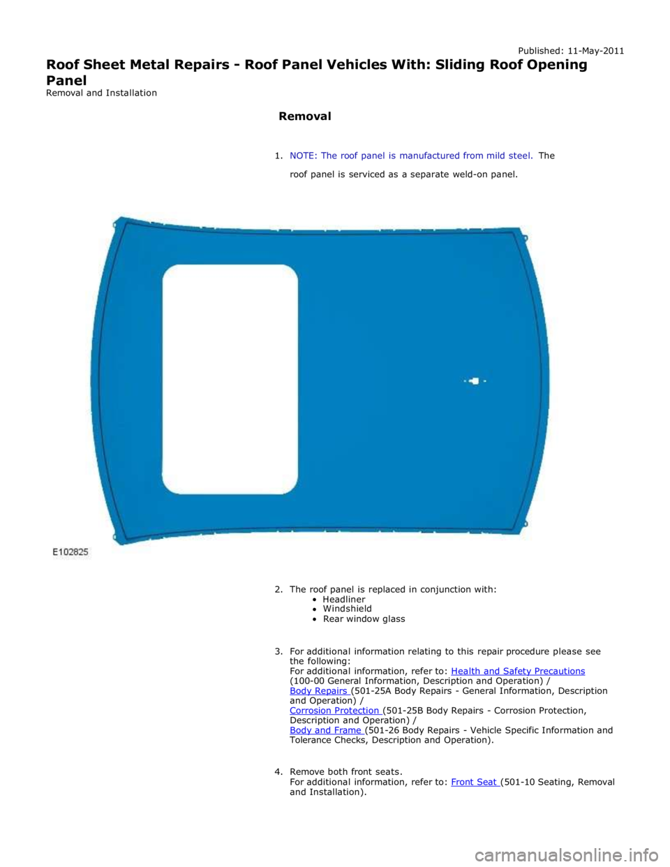
1. NOTE: The roof panel is manufactured from mild steel. The
roof panel is serviced as a separate weld-on panel.
2. The roof panel is replaced in conjunction with:
Headliner
Windshield
Rear window glass
3. For additional information relating to this repair procedure please see
the following:
For additional information, refer to: Health and Safety Precautions (100-00 General Information, Description and Operation) /
Body Repairs (501-25A Body Repairs - General Information, Description and Operation) /
Corrosion Protection (501-25B Body Repairs - Corrosion Protection, Description and Operation) /
Body and Frame (501-26 Body Repairs - Vehicle Specific Information and Tolerance Checks, Description and Operation).
4. Remove both front seats.
For additional information, refer to: Front Seat (501-10 Seating, Removal and Installation).
Page 2829 of 3039

(414-01 Battery, Mounting and Cables, General Procedures).
6. Disconnect the generator electrical connectors.
7. Remove the windshield glass.
For additional information, refer to: Windshield Glass (501-11 Glass, Frames and Mechanisms, Removal and Installation).
8. Remove the rear window glass.
For additional information, refer to: Rear Window Glass (501-11 Glass, Frames and Mechanisms, Removal and Installation).
9. Remove the roof opening panel frame.
For additional information, refer to: Roof Opening Panel Frame (501-17 Roof Opening Panel, Removal and Installation).
10. Remove the driver and passenger side front scuff plate trim panels.
For additional information, refer to: Front Scuff Plate Trim Panel (501-05 Interior Trim and Ornamentation, Removal and Installation).
11. Remove the driver and passenger side rear scuff plate trim panels.
For additional information, refer to: Rear Scuff Plate Trim Panel (501-05 Interior Trim and Ornamentation, Removal and Installation).
12. Remove the driver and passenger side air curtain modules.
For additional information, refer to: Side Air Curtain Module (501-20B Supplemental Restraint System, Removal and Installation).
13. Remove the rear seat backrest.
14. Remove the driver and passenger side rear safety belt retractors.
For additional information, refer to: Rear Safety Belt Retractor (501-20A Safety Belt System, Removal and Installation).
15. Remove the rear center safety belt retractor.
For additional information, refer to: Rear Center Safety Belt Retractor (501-20A Safety Belt System, Removal and Installation).
16. Remove the driver and passenger side RF filters.
17. Remove the diversity antenna module.
18. Remove the antenna.
For additional information, refer to: Navigation System Antenna (419-07 Navigation System, Removal and Installation).
19. Release and position the roof wiring harnesses to one side
20. Position the roof opening panel front and rear drain hoses to one side.
21. Remove the driver and passenger side roof mouldings.
22. Drill out the spot welds.
www.JagDocs.com
Page 2835 of 3039
Published: 11-May-2011
Roof Sheet Metal Repairs - Roof Panel Vehicles Without: Sliding Roof Opening
Panel
Removal and Installation
Removal
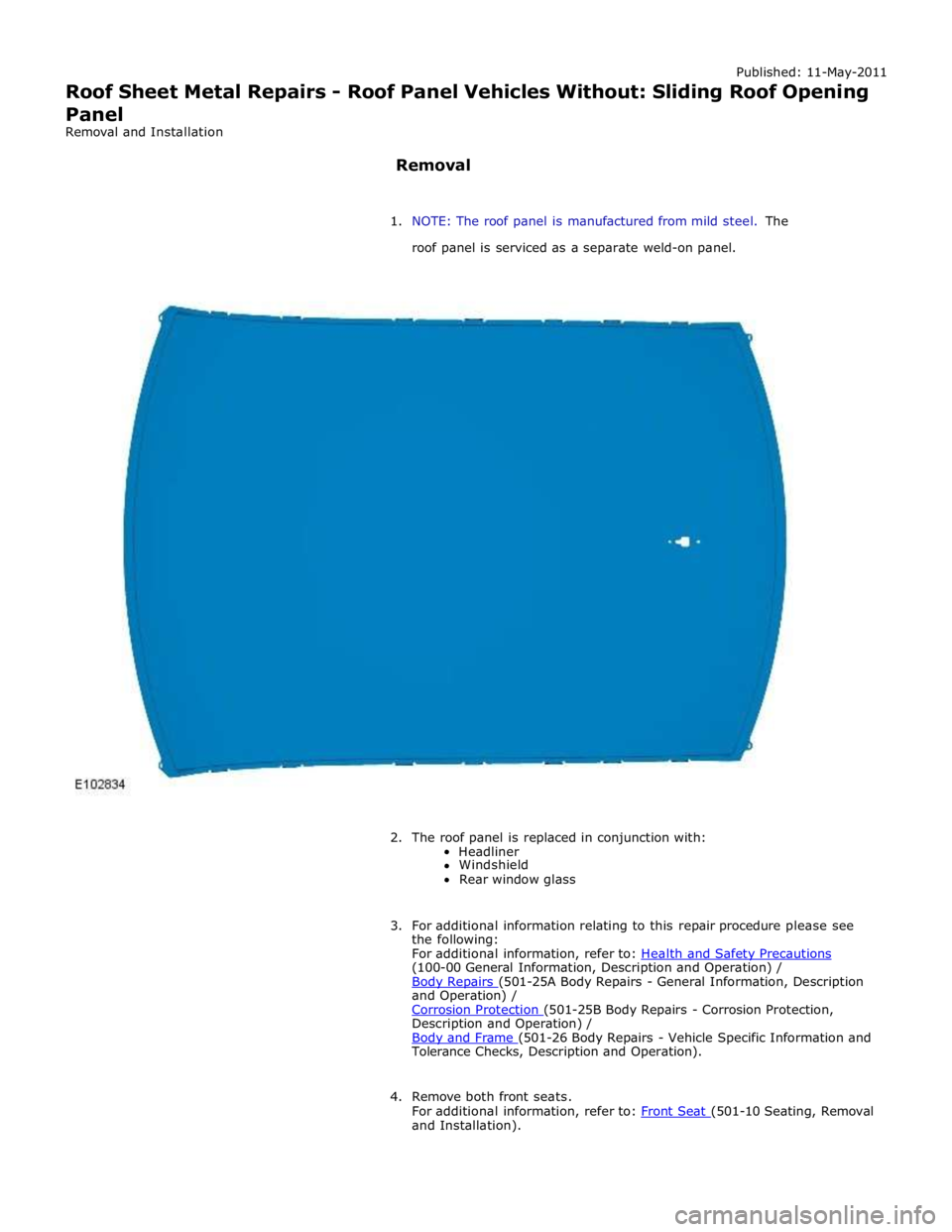
1. NOTE: The roof panel is manufactured from mild steel. The
roof panel is serviced as a separate weld-on panel.
2. The roof panel is replaced in conjunction with:
Headliner
Windshield
Rear window glass
3. For additional information relating to this repair procedure please see
the following:
For additional information, refer to: Health and Safety Precautions (100-00 General Information, Description and Operation) /
Body Repairs (501-25A Body Repairs - General Information, Description and Operation) /
Corrosion Protection (501-25B Body Repairs - Corrosion Protection, Description and Operation) /
Body and Frame (501-26 Body Repairs - Vehicle Specific Information and Tolerance Checks, Description and Operation).
4. Remove both front seats.
For additional information, refer to: Front Seat (501-10 Seating, Removal and Installation).
Page 2836 of 3039

(414-01 Battery, Mounting and Cables, General Procedures).
6. Disconnect the generator electrical connectors.
7. Remove the windshield glass.
For additional information, refer to: Windshield Glass (501-11 Glass, Frames and Mechanisms, Removal and Installation).
8. Remove the rear window glass.
For additional information, refer to: Rear Window Glass (501-11 Glass, Frames and Mechanisms, Removal and Installation).
9. Remove the headliner.
For additional information, refer to: Headliner (501-05 Interior Trim and Ornamentation, Removal and Installation).
10. Remove the driver and passenger side front scuff plate trim panels.
For additional information, refer to: Front Scuff Plate Trim Panel (501-05 Interior Trim and Ornamentation, Removal and Installation).
11. Remove the driver and passenger side rear scuff plate trim panels.
For additional information, refer to: Rear Scuff Plate Trim Panel (501-05 Interior Trim and Ornamentation, Removal and Installation).
12. Remove the driver and passenger side air curtain modules.
For additional information, refer to: Side Air Curtain Module (501-20B Supplemental Restraint System, Removal and Installation).
13. Remove the rear seat backrest.
14. Remove the driver and passenger side rear safety belt retractors.
For additional information, refer to: Rear Safety Belt Retractor (501-20A Safety Belt System, Removal and Installation).
15. Remove the rear center safety belt retractor.
For additional information, refer to: Rear Center Safety Belt Retractor (501-20A Safety Belt System, Removal and Installation).
16. Remove the driver and passenger side RF filters.
17. Remove the diversity antenna module.
18. Remove the antenna.
For additional information, refer to: Navigation System Antenna (419-07 Navigation System, Removal and Installation).
19. Release and position the roof wiring harnesses to one side
20. Remove the driver and passenger side roof mouldings.
21. Drill out the spot welds.
Page 2843 of 3039
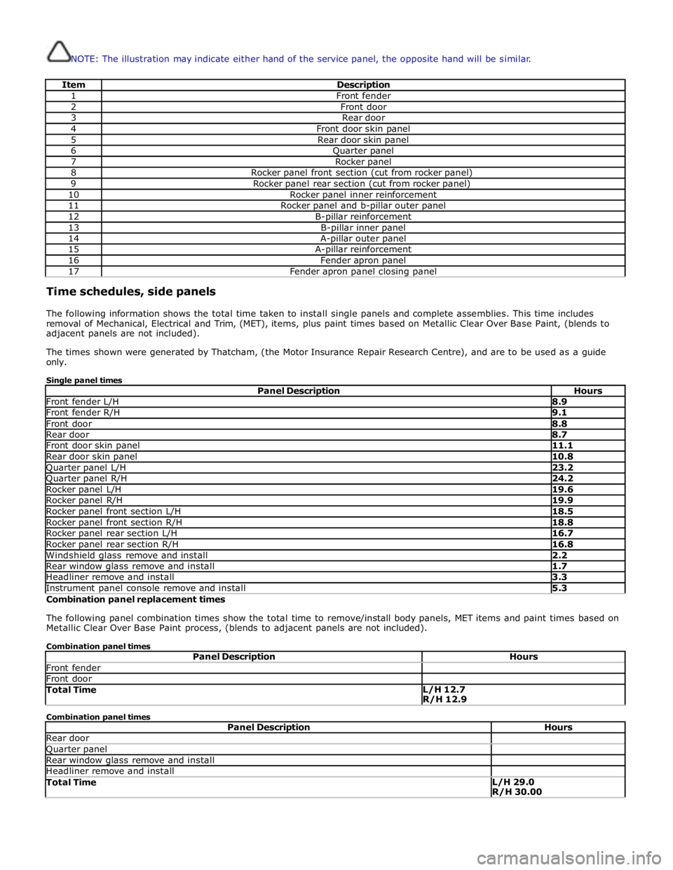
NOTE: The illustration may indicate either hand of the service panel, the opposite hand will be similar.
Item Description 1 Front fender 2 Front door 3 Rear door 4 Front door skin panel 5 Rear door skin panel 6 Quarter panel 7 Rocker panel 8 Rocker panel front section (cut from rocker panel) 9 Rocker panel rear section (cut from rocker panel) 10 Rocker panel inner reinforcement 11 Rocker panel and b-pillar outer panel 12 B-pillar reinforcement 13 B-pillar inner panel 14 A-pillar outer panel 15 A-pillar reinforcement 16 Fender apron panel 17 Fender apron panel closing panel Time schedules, side panels
The following information shows the total time taken to install single panels and complete assemblies. This time includes
removal of Mechanical, Electrical and Trim, (MET), items, plus paint times based on Metallic Clear Over Base Paint, (blends to
adjacent panels are not included).
The times shown were generated by Thatcham, (the Motor Insurance Repair Research Centre), and are to be used as a guide
only.
Single panel times
Panel Description Hours Front fender L/H 8.9 Front fender R/H 9.1 Front door 8.8 Rear door 8.7 Front door skin panel 11.1 Rear door skin panel 10.8 Quarter panel L/H 23.2 Quarter panel R/H 24.2 Rocker panel L/H 19.6 Rocker panel R/H 19.9 Rocker panel front section L/H 18.5 Rocker panel front section R/H 18.8 Rocker panel rear section L/H 16.7 Rocker panel rear section R/H 16.8 Windshield glass remove and install 2.2 Rear window glass remove and install 1.7 Headliner remove and install 3.3 Instrument panel console remove and install 5.3 Combination panel replacement times
The following panel combination times show the total time to remove/install body panels, MET items and paint times based on
Metallic Clear Over Base Paint process, (blends to adjacent panels are not included).
Combination panel times
Panel Description Hours Front fender Front door Total Time L/H 12.7
R/H 12.9 Combination panel times
Panel Description Hours Rear door Quarter panel Rear window glass remove and install Headliner remove and install Total Time L/H 29.0
R/H 30.00
Page 2844 of 3039
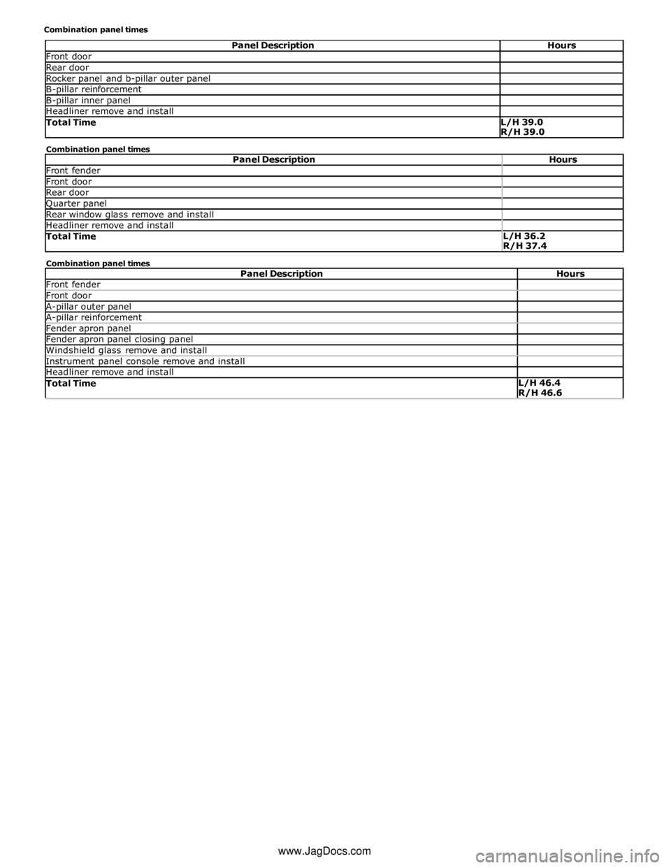
Front door Rear door Rocker panel and b-pillar outer panel B-pillar reinforcement B-pillar inner panel Headliner remove and install Total Time L/H 39.0
R/H 39.0 Combination panel times
Panel Description Hours Front fender Front door Rear door Quarter panel Rear window glass remove and install Headliner remove and install Total Time L/H 36.2
R/H 37.4 Combination panel times
Panel Description Hours Front fender Front door A-pillar outer panel A-pillar reinforcement Fender apron panel Fender apron panel closing panel Windshield glass remove and install Instrument panel console remove and install Headliner remove and install Total Time L/H 46.4
R/H 46.6 www.JagDocs.com