window JAGUAR XFR 2010 1.G Repair Manual
[x] Cancel search | Manufacturer: JAGUAR, Model Year: 2010, Model line: XFR, Model: JAGUAR XFR 2010 1.GPages: 3039, PDF Size: 58.49 MB
Page 2426 of 3039
Published: 11-May-2011
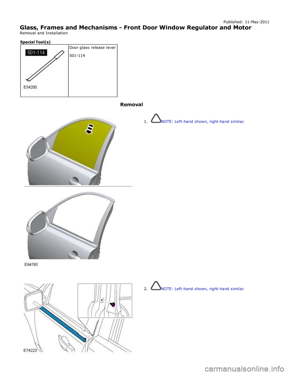
Glass, Frames and Mechanisms - Front Door Window Regulator and Motor
Removal and Installation
Removal
1. NOTE: Left-hand shown, right-hand similar.
2. NOTE: Left-hand shown, right-hand similar. Door glass release lever
501-114 Special Tool(s)
Page 2434 of 3039
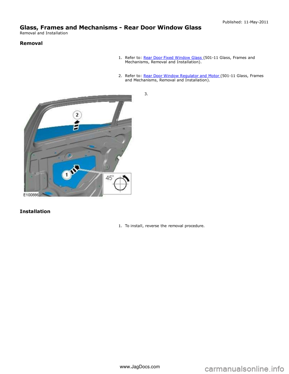
Mechanisms, Removal and Installation).
2. Refer to: Rear Door Window Regulator and Motor (501-11 Glass, Frames and Mechanisms, Removal and Installation).
3.
Installation
1. To install, reverse the removal procedure. www.JagDocs.com
Page 2435 of 3039
Published: 11-May-2011
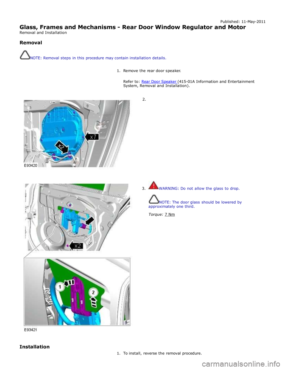
Glass, Frames and Mechanisms - Rear Door Window Regulator and Motor
Removal and Installation
Removal
NOTE: Removal steps in this procedure may contain installation details.
1. Remove the rear door speaker.
Refer to: Rear Door Speaker (415-01A Information and Entertainment System, Removal and Installation).
2.
3. WARNING: Do not allow the glass to drop.
NOTE: The door glass should be lowered by
approximately one third.
Torque: 7 Nm
Installation
1. To install, reverse the removal procedure.
Page 2436 of 3039
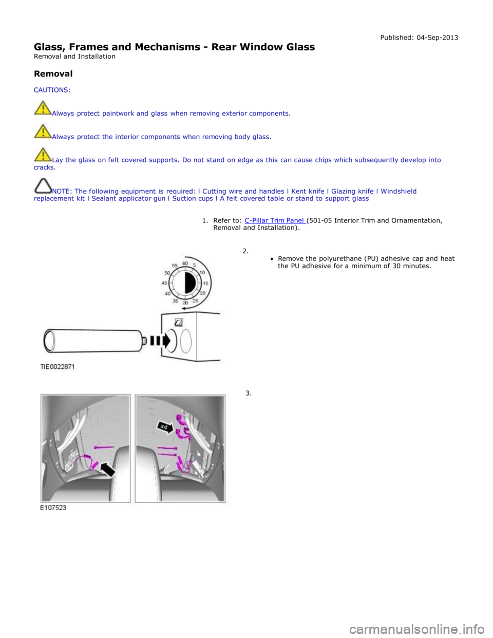
Glass, Frames and Mechanisms - Rear Window Glass
Removal and Installation
Removal
CAUTIONS:
Always protect paintwork and glass when removing exterior components.
Always protect the interior components when removing body glass. Published: 04-Sep-2013
Lay the glass on felt covered supports. Do not stand on edge as this can cause chips which subsequently develop into
cracks.
NOTE: The following equipment is required: l Cutting wire and handles l Kent knife l Glazing knife l Windshield
replacement kit l Sealant applicator gun l Suction cups l A felt covered table or stand to support glass
1. Refer to: C-Pillar Trim Panel (501-05 Interior Trim and Ornamentation, Removal and Installation).
2.
Remove the polyurethane (PU) adhesive cap and heat
the PU adhesive for a minimum of 30 minutes.
3.
Page 2437 of 3039
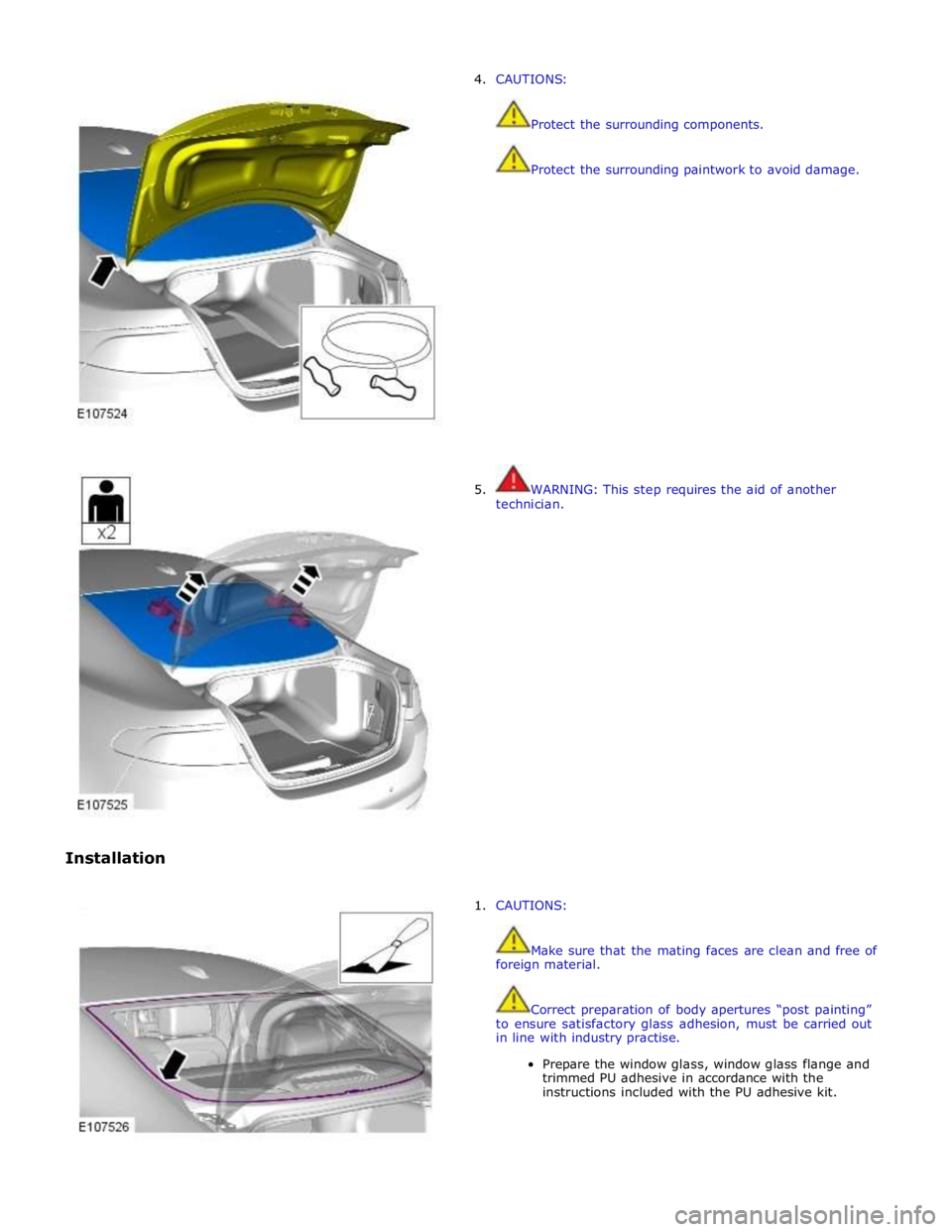
Installation 4. CAUTIONS:
Protect the surrounding components.
Protect the surrounding paintwork to avoid damage.
5. WARNING: This step requires the aid of another
technician.
1. CAUTIONS:
Make sure that the mating faces are clean and free of
foreign material.
Correct preparation of body apertures “post painting”
to ensure satisfactory glass adhesion, must be carried out
in line with industry practise.
Prepare the window glass, window glass flange and
trimmed PU adhesive in accordance with the
instructions included with the PU adhesive kit.
Page 2441 of 3039
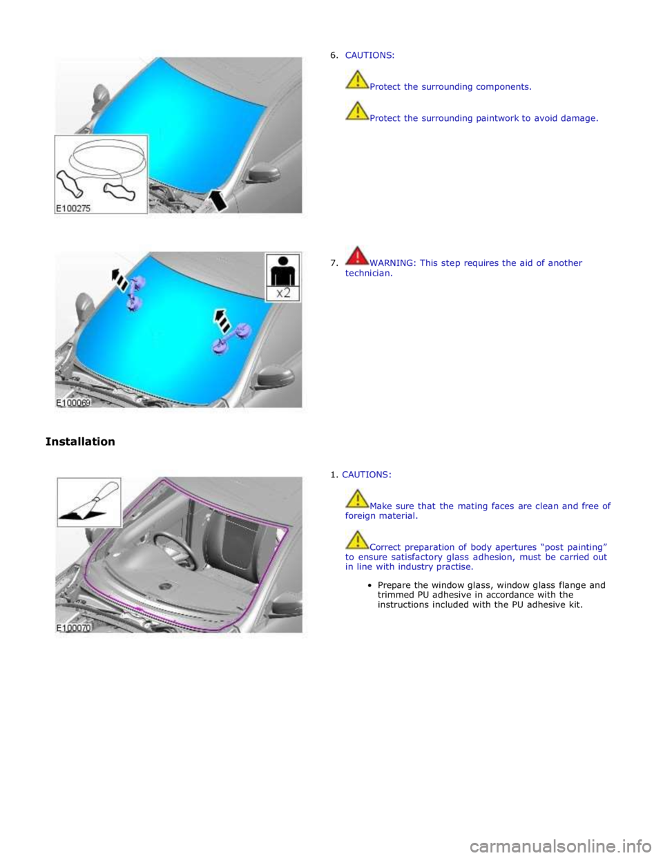
Installation 6. CAUTIONS:
Protect the surrounding components.
Protect the surrounding paintwork to avoid damage.
7. WARNING: This step requires the aid of another
technician.
1. CAUTIONS:
Make sure that the mating faces are clean and free of
foreign material.
Correct preparation of body apertures “post painting”
to ensure satisfactory glass adhesion, must be carried out
in line with industry practise.
Prepare the window glass, window glass flange and
trimmed PU adhesive in accordance with the
instructions included with the PU adhesive kit.
Page 2444 of 3039
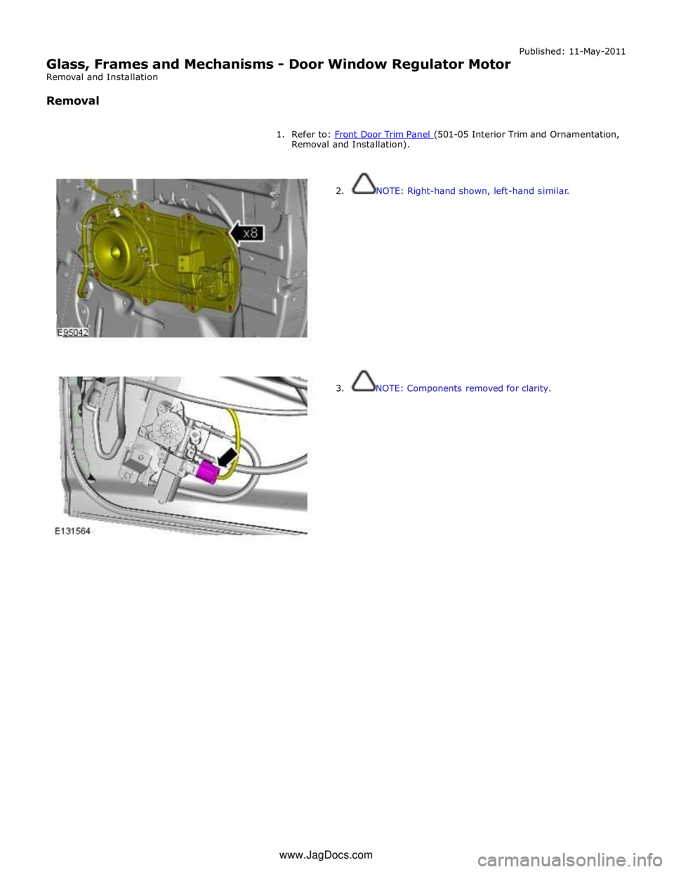
Glass, Frames and Mechanisms - Door Window Regulator Motor
Removal and Installation
Removal Published: 11-May-2011
1. Refer to: Front Door Trim Panel (501-05 Interior Trim and Ornamentation, Removal and Installation).
2. NOTE: Right-hand shown, left-hand similar.
3. NOTE: Components removed for clarity. www.JagDocs.com
Page 2445 of 3039
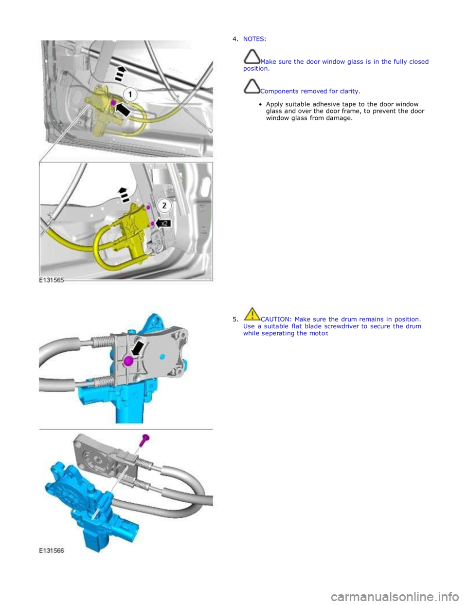
4. NOTES:
Make sure the door window glass is in the fully closed
position.
Components removed for clarity.
Apply suitable adhesive tape to the door window
glass and over the door frame, to prevent the door
window glass from damage.
5. CAUTION: Make sure the drum remains in position.
Use a suitable flat blade screwdriver to secure the drum
while seperating the motor.
Page 2495 of 3039
Published: 18-Mar-2014
Handles, Locks, Latches and Entry Systems - Locks, Latches and Entry Systems
Diagnosis and Testing
Principle of Operation
For a detailed description of the locks, latches and entry systems and operation, refer to the relevant Description and
Operation section of the workshop manual. REFER to: Handles, Locks, Latches and Entry Systems (501-14, Description and
Operation).
Inspection and Verification
CAUTION: Diagnosis by substitution from a donor vehicle is NOT acceptable. Substitution of control modules does not
guarantee confirmation of a fault and may also cause additional faults in the vehicle being checked and/or the donor vehicle
NOTE: Check and rectify basic faults before beginning diagnostic routines involving pinpoint tests
1. Verify the customer concern, to be sure the correct issue is investigated
2. Visually inspect for obvious signs of damage and system integrity
Visual Inspection
Mechanical Electrical
Incorrectly aligned door(s), hood or tailgate
Fuel filler door lock actuator
Hood release handle
Hood release cables
Hood latch(es)
Exterior door handle(s)
Interior door handle(s)
Cable(s)
Tailgate release switch
Rear window release switch
Fuses
Wiring harness
Wiring connector(s)
Door lock actuator(s)
Remote transmitter (key-fob or smart key)
Central locking switches
Controller Area Network (CAN) circuits
Radio frequency (RF) receiver
Central junction box (CJB)
Loose or corroded connections
3. If an obvious cause for an observed or reported concern is found, correct the cause (if possible) before proceeding to
the next step
4. If the cause is not visually evident verify the symptom and refer to the Symptom Chart, alternatively check for
Diagnostic Trouble Codes (DTCs) and refer to the DTC Index
Symptom Chart
NOTE: Complete the diagnostic steps below to confirm any concern prior to replacing any component
Symptom Possible Causes Action The message center indicates that the
hood, the luggage compartment is
open when it appears to be closed
Incorrect striker
alignment/adjustment
Ajar switch circuit short circuit to
ground
Ajar switch failure
Check/adjust the strikers as
necessary
Check for DTCs indicating an ajar
switch fault. Refer to the DTC index Vehicle indicates a miss-lock when the
hood, luggage compartment appear to
be closed Fuel flap does not lock/unlock
Fuel flap cable detached from body
Fuel flap actuator detached from
mounting bracket
Fuel flap actuator disconnected
Fuel flap actuator failure
Check the condition and installation
of the fuel flap cable
Check the security of the fuel flap
actuator and bracket
Check the security of the actuator
electrical connector
Check for DTCs indicating a fuel flap
actuator fault. Refer to the DTC
index Door(s) will not unlatch/open when
using outside door handle
Exterior door handle
condition/installation
Exterior release cable disconnected
from exterior door handle or door
latch
Check the exterior door handle
condition and installation
Check the condition and security of
the exterior release cable
Single door will not open from the
Page 2517 of 3039
Handles, Locks, Latches and Entry Systems - Front Door Latch
Removal and Installation
Removal Published: 04-Feb-2013
1. Refer to: Front Door Window Glass (501-11 Glass, Frames and Mechanisms, Removal and Installation).
2. NOTE: Left-hand shown, right-hand similar.
Refer to: Exterior Front Door Handle (501-14 Handles, Locks, Latches and Entry Systems, Removal and Installation).
3. Refer to: Front Door Trim Panel (501-05 Interior Trim and Ornamentation, Removal and Installation).
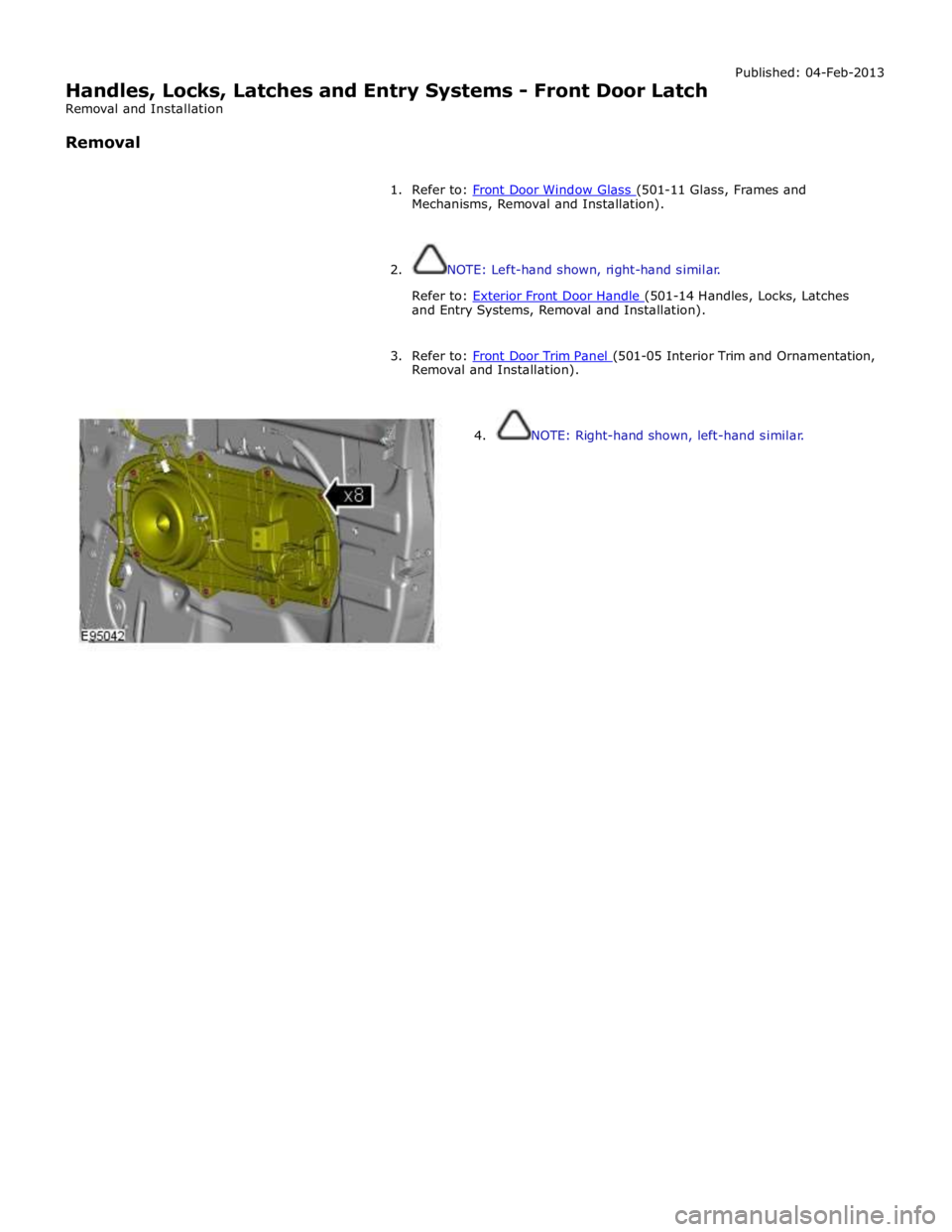
4. NOTE: Right-hand shown, left-hand similar.