PID JAGUAR XFR 2010 1.G Workshop Manual
[x] Cancel search | Manufacturer: JAGUAR, Model Year: 2010, Model line: XFR, Model: JAGUAR XFR 2010 1.GPages: 3039, PDF Size: 58.49 MB
Page 50 of 3039
disconnected, a Radio Code Saver will allow sufficient current to pass to maintain the radio receiver/cassette player/mini disc
player and compact disc player memory, operate the clock and supply the door operated interior lights while isolating the
battery in the event of a short circuit.
Reconnecting the Battery
WARNING: If the battery has been on bench charge the cells may be giving off explosive hydrogen gas. Avoid creating
sparks, and if in doubt cover the vent plugs or covers with a damp cloth.
Always make sure that all electrical systems are switched OFF before reconnecting the battery to avoid causing sparks or
damage to sensitive electrical equipment.
Always reconnect the battery positive lead first and the negative last, ensuring that there is a good electrical contact and the
battery terminals are secure.
Restart the clock (where installed) and set it to the correct time.
Enter the radio receiver/cassette player/mini disc player and compact disc player keycodes and preset' frequencies, if known.
Following reconnection of the battery, the engine should be allowed to idle until it has reached normal operating temperature
as the stored idle and drive values contained within the ECM have been lost. Allow the vehicle to idle for a further three
minutes. Drive the vehicle at constant speeds of approximately 48 km/h (30 mph), 64 km/h (40 mph), 80 km/h (50 mph), 96
km/h (60 mph) and 112 km/h (70 mph) for three minutes each. This will allow the ECM to relearn idle and drive values, and
may cause driveability concerns if the procedure is not carried out.
Connecting a Slave Battery Using Jump Leads
WARNING: If the slave battery has recently been charged and is gassing, cover the vent plugs or covers with a damp
cloth to reduce the risk of explosion should arcing occur when connecting the jump leads.
CAUTIONS:
A discharged battery condition may have been caused by an electrical short circuit. If this condition exists there will be
an apparently live circuit on the vehicle even when all circuits are switched off. This can cause arcing when the jump leads are
connected.
Whilst it is not recommended that the vehicle is jump started, it is recognized that this may occasionally be the only
practical way to mobilize a vehicle. In such an instance the discharged battery must be recharged immediately after jump
starting to avoid permanent damage.
Always make sure that the jump leads are adequate for the task. Heavy duty cables must be used.
Always make sure that the slave battery is of the same voltage as the vehicle battery. The batteries must be connected
in parallel.
Always make sure that switchable electric circuits are switched off before connecting jump leads. This reduces the risk
of sparks occurring when the final connection is made.
WARNING: Make sure that the ends of the jump leads do not touch each other or ground against the vehicle body at any
time while the leads are attached to the battery. A fully charged battery, if shorted through jump leads, can discharge at a rate
well above 1000 amps causing violent arcing and very rapid heating of the jump leads and terminals, and can even cause the
battery to explode.
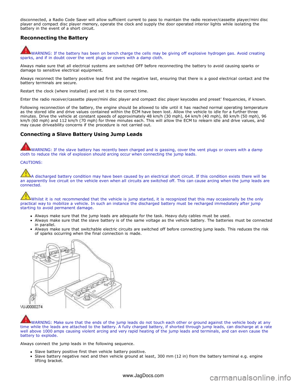
Always connect the jump leads in the following sequence.
Slave battery positive first then vehicle battery positive.
Slave battery negative next and then vehicle ground at least, 300 mm (12 in) from the battery terminal e.g. engine
lifting bracket. www.JagDocs.com
Page 54 of 3039

Hydrofluorocarbon HFC High tension HT Hydrocarbon HC Idle Air Control IAC
Stepper motor driven device which varies the volume of air by-passing the
throttle to maintain the programmed idle speed Intake Air Temperature IAT Temperature of intake air Inertia Fuel Shut-off IFS
An inertia system that shuts off the fuel supply when activated by pre-determined force limits brought about by (e.g.) collision Input Shaft Speed ISS Indicates input shaft speed Key On, Engine Off KOEO Key On, Engine Running KOER Kilogram (mass) kg Kilogram (force) kgf Kilogram force per square
centimeter kgf/cm²
Kilometer km Kilometer per hour km/h Kilopascal kPa Kilovolt kV Knock Sensor KS
Sensor which detects the onset of detonation, and signals the ECM to
retard the ignition Liquid Crystal Display LCD
Optical digital display system, to which applied voltage varies the way the crystals reflect light, thereby modifying the display Lighting Control Module LCM Light Emitting Diode LED Low Tension LT
Primary circuit of the ignition system, linking the battery to the primary winding in the ignition coil Left-Hand LH Left-Hand Drive LHD Mass Air Flow MAF
System which provides information on the mass flow rate of the intake air
to the engine Manifold Absolute Pressure MAP Absolute pressure of the intake manifold air Manifold Absolute Pressure and Temperature MAPT
Malfunction Indicator Lamp MIL
A required on-board indicator to alert the driver of an emission related
malfunction Meter (measurement) m Metric (screw thread, e.g. M8) M Farad F Unit of electrical capacitance Millimeter mm Millimeter of mercury mmHg Millisecond ms Model year MY Newton N SI unit of force. 1 N = 0.2248 pounds force Newton Meter Nm SI unit of torque. Must not be confused with nm (nanometer) Negative Temperature
Coefficient NTC
Naturally aspirated N/A
Fuelling system using intake air at atmospheric pressure; not supercharged or turbocharged Noise, Vibration and Harshness NVH North American Specification NAS Vehicles for sale in the USA and Canadian markets On-Board Diagnostic OBD
A system that monitors some or all computer input and output control
signals. Signal(s) outside the pre-determined limits imply a fault in the system or a related system Oxides of Nitrogen Nox Oxygen Sensor O2S A sensor which detects oxygen content in the exhaust gases On-board Refuelling Vapour Recovery ORVR
Output State Control OSC Output Shaft Speed OSS Passenger Air Bag Deactivation PAD Pulsed Secondary Air Injection PAIR Passive Anti-Theft System PATS Positive Crankcase Ventilation PCV Parameter Identification PID
An index number referring to a parameter within a module without knowledge of its storage location Park/Neutral Position PNP Pulse Width Modulation PWM Programmable Electronic
Control Units System PECUS
Process whereby a common ECM is programmed on the production line to
suit the market requirements of a particular vehicle
Page 60 of 3039

Have a suitable fire extinguisher available when using welding or heating equipment.
First Aid
Apart from meeting any legal requirements it is desirable for someone in the workshop to be trained in First Aid procedures.
Splashes in the eye should be flushed carefully with clean water for at least ten minutes.
Soiled skin should be washed with soap and water.
Individuals affected by inhalation of gases, fumes etc. should be removed to fresh air immediately. If effects persist, consult a
doctor.
If liquids are swallowed inadvertently, consult a doctor giving the information on the container or label. Do not induce vomiting
unless this action is indicated on the label.
Fluoroelastomer
See Viton.
Foams - Polyurethane
See also Fire.
Used in sound and noise insulation. Cured foams used in seat and trim cushioning.
Follow manufacturer's instructions.
Unreacted components are irritating and may be harmful to the skin and eyes. Wear gloves and goggles.
Individuals with chronic respiratory diseases, asthma, bronchial medical problems, or histories of allergic diseases should not
work in or near uncured materials.
The components, vapors or spray mists can cause direct irritation, sensitivity reactions and may be toxic or harmful.
Vapors and spray mists must not be inhaled. These materials must be applied with adequate ventilation and respiratory
protection. Do not remove the respirator immediately after spraying, wait until the vapor/mists have cleared.
Burning of the uncured components and the cured foams can generate toxic and harmful fumes. Smoking, naked flames or the
use of electrical equipment during foaming operations and until vapors/mists have cleared should not be allowed. Any heat
cutting of cured foams or partially cured foams should be conducted with extraction ventilation.
Freon
See Air Conditioning Refrigerant.
Fuels
See also, Fire, Legal Aspects, Chemicals and Solvents.
Avoid skin contact with fuel where possible. Should contact occur, wash the affected skin with soap and water.
Gasoline (Petrol)
Highly flammable - observe No Smoking policy.
Swallowing can result in mouth and throat irritation and absorption from the stomach can result in drowsiness and
unconsciousness. Small amounts can be fatal to children. Aspiration of liquid into the lungs e.g. through vomiting, is a very
serious hazard.
Gasoline dries the skin and can cause irritation and dermatitis on prolonged or repeated contact. Liquid in the eye causes
severe pain.
Motor gasoline may contain appreciable quantities of benzene, which is toxic upon inhalation, and the concentration of
gasoline vapors must be kept very low. High concentrations will cause eye, nose and throat irritation, nausea, headache,
depression and symptoms of drunkenness. Very high concentrations will result in rapid loss of consciousness.
Ensure there is adequate ventilation when handling and using gasoline. Great care must be taken to avoid the serious
consequences of inhalation in the event of vapor build up arising from spillages in confined spaces.
Special precautions apply to cleaning and maintenance operations on gasoline storage tanks.
Gasoline should not be used as a cleaning agent. It must not be siphoned by mouth. See First Aid.
Gas - oil (Diesel Fuel)
See warnings and cautions in relevant manual sections.
Combustible.
www.JagDocs.com
Page 101 of 3039
Published: 11-May-2011
General Information - Supplemental Restraint System (SRS) Health and
Safety Precautions
Description and Operation
WARNINGS:
Only qualified technicians are allowed to work on pyrotechnic components.
INHALED: Exposure to pyrotechnic residue may cause low blood pressure, severe headache, irritation of mucous
membranes, fainting, shortness of breath or rapid pulse. Move a victim to fresh air. Seek immediate medical attention.
EYE CONTACT: Exposure to unburned pyrotechnic residue may cause irritation, burning and etching of the eyes. Flush
immediately with plenty of cold running water for at least 15 minutes. Seek immediate medical attention.
EYE CONTACT: Exposure to burned pyrotechnic residue may cause irritation, burning and etching of the eyes. Flush
immediately with diluted boric acid solution. Seek immediate medical attention.
SKIN CONTACT: Unburned pyrotechnic residue may be rapidly absorbed through the skin in toxic quantities. Wash
immediately with plenty of soap and water. Seek medical attention.
SKIN CONTACT: Burned pyrotechnic residue may be rapidly absorbed through the skin in toxic quantities. Wash with
plenty of water. Do not use soap. Seek medical attention.
SWALLOWED: Unburned pyrotechnic residue is extremely toxic. If conscious drink plenty of water then induce vomiting.
Seek immediate medical attention. If unconscious, or in convulsions do not attempt to induce vomiting or give anything by
mouth. Seek immediate medical attention.
SWALLOWED: Burned pyrotechnic residue is extremely toxic. Drink plenty of water and seek immediate medical attention.
The deployment key must only be accessible to authorized personnel.
Make sure that the deployment key remains removed from the deployment equipment except during deployment.
If permenantly disabling or enabling the passenger air bag a new seat belt for vehicles without or with a passenger air
bag must be installed.
Undeployed pyrotechnic components must not be deployed in the vehicle.
Pyrotechnic components must be deployed following local regulations.
Check thoroughly that no loose objects can be spread during the deployment of pyrotechnic components.
Pyrotechnic components must be transported following local regulations.
Never carry out any electrical measurement on disconnected, undeployed pyrotechnic components.
Pyrotechnic components must not be disassembled.
Pyrotechnic components are not interchangeable between vehicles.
Always carry a live air bag module away from the body with the air bag or trim cover pointing upwards.
Page 309 of 3039
Removal and Installation),
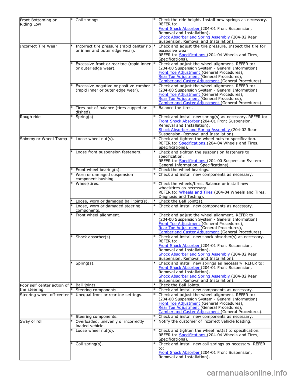
Shock Absorber and Spring Assembly (204-02 Rear Suspension, Removal and Installation). Incorrect Tire Wear
* Incorrect tire pressure (rapid center rib
or inner and outer edge wear). * Check and adjust the tire pressure. Inspect the tire for
excessive wear.
REFER to: Specifications (204-04 Wheels and Tires, Specifications). * Excessive front or rear toe (rapid inner
or outer edge wear). * Check and adjust the wheel alignment. REFER to:
(204-00 Suspension System - General Information)
Front Toe Adjustment (General Procedures), Rear Toe Adjustment (General Procedures), Camber and Caster Adjustment (General Procedures). * Excessive negative or positive camber
(rapid inner or outer edge wear). * Check and adjust the wheel alignment. REFER to:
(204-00 Suspension System - General Information)
Front Toe Adjustment (General Procedures), Rear Toe Adjustment (General Procedures), Camber and Caster Adjustment (General Procedures). * Tires out of balance (tires cupped or dished). * Balance the tires. Rough ride * Spring(s)
* Check and install new spring(s) as necessary. REFER to:
Front Shock Absorber (204-01 Front Suspension, Removal and Installation),
Shock Absorber and Spring Assembly (204-02 Rear Suspension, Removal and Installation). Shimmy or Wheel Tramp * Loose wheel nut(s).
* Check and tighten the wheel nuts to specification.
REFER to: Specifications (204-04 Wheels and Tires, Specifications). * Loose front suspension fasteners.
* Check and tighten the suspension fasteners to
specification.
REFER to: Specifications (204-00 Suspension System - General Information, Specifications). * Front wheel bearing(s). * Check the wheel bearings. * Worn or damaged suspension component bushing. * Check and install new components as necessary. * Wheel/tires.
* Check the wheels/tires. Balance or install new
wheel/tires as necessary.
REFER to: Wheels and Tires (204-04 Wheels and Tires, Diagnosis and Testing). * Loose, worn or damaged ball joint(s). * Check the Ball Joint(s). * Loose, worn or damaged steering components. * Check and install new components as necessary. * Front wheel alignment.
* Check and adjust the wheel alignment. REFER to:
(204-00 Suspension System - General Information)
Front Toe Adjustment (General Procedures), Rear Toe Adjustment (General Procedures), Camber and Caster Adjustment (General Procedures). * Shock absorber(s). * Check and install new shock absorber(s) as necessary.
REFER to:
Front Shock Absorber (204-01 Front Suspension, Removal and Installation),
Shock Absorber and Spring Assembly (204-02 Rear Suspension, Removal and Installation). * Spring(s).
* Check and install new springs as necessary. REFER to:
Front Shock Absorber (204-01 Front Suspension, Removal and Installation),
Shock Absorber and Spring Assembly (204-02 Rear Suspension, Removal and Installation). Poor self center action of
the steering * Ball joints. * Check the Ball Joints. * Steering components. * Check and install new components as necessary. Steering wheel off-center * Unequal front or rear toe settings.
* Check and adjust the wheel alignment. REFER to:
(204-00 Suspension System - General Information)
Front Toe Adjustment (General Procedures), Rear Toe Adjustment (General Procedures), Camber and Caster Adjustment (General Procedures). * Steering components. * Check and install new components as necessary. Sway or roll
* Overloaded, unevenly or incorrectly
loaded vehicle. * Notify the customer of incorrect vehicle loading. * Loose wheel nut(s).
* Check and tighten the wheel nut(s) to specification.
REFER to: Specifications (204-04 Wheels and Tires, Specifications). * Coil spring(s).
* Check and install new coil springs as necessary. REFER
to:
Front Shock Absorber (204-01 Front Suspension, Removal and Installation),
Page 441 of 3039
provides the following benefits:
Maintain optimal fuel consumption.
Maintain ride and handling characteristics.
Reduce the risk of rapid tire deflation - which may be caused by under inflated tires.
Comply with legislation requirements in relevant markets.
CAUTION: TPMS is not intended as a replacement for regular tire pressure and tire condition checks and should be
considered as additional to good tire maintenance practices.
The TPMS measures the pressure in each of the vehicle's tires and issues warnings to the driver if any of the pressures deviate
from defined tolerances. The space saver spare wheel is not monitored.
NOTE: TPMS is not designed to warn the driver of a tire 'blow-out', as due to the short duration of a 'blow-out', it is not
possible to give the driver sufficient warning that such an event is occurring. The design of the TPMS is to assist the driver in
keeping the tires at the correct pressure, which will assist to reduce the likelihood of a tire 'blow-out' occurring.
Page 586 of 3039
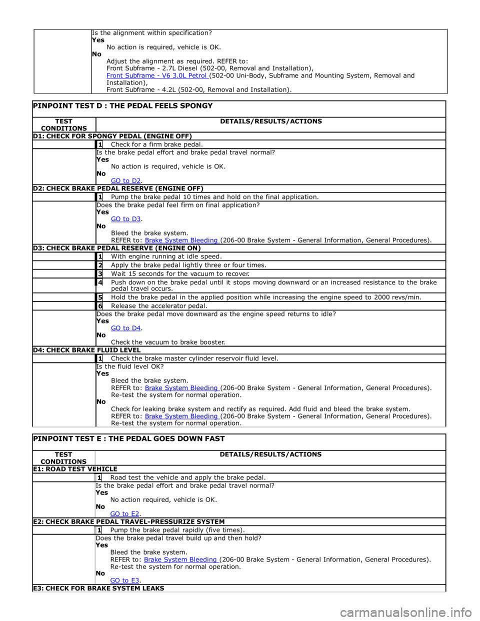
TEST
CONDITIONS DETAILS/RESULTS/ACTIONS D1: CHECK FOR SPONGY PEDAL (ENGINE OFF) 1 Check for a firm brake pedal. Is the brake pedal effort and brake pedal travel normal? Yes
No action is required, vehicle is OK.
No
GO to D2. D2: CHECK BRAKE PEDAL RESERVE (ENGINE OFF) 1 Pump the brake pedal 10 times and hold on the final application. Does the brake pedal feel firm on final application? Yes
GO to D3. No
Bleed the brake system.
REFER to: Brake System Bleeding (206-00 Brake System - General Information, General Procedures). D3: CHECK BRAKE PEDAL RESERVE (ENGINE ON) 1 With engine running at idle speed. 2 Apply the brake pedal lightly three or four times. 3 Wait 15 seconds for the vacuum to recover. 4 Push down on the brake pedal until it stops moving downward or an increased resistance to the brake pedal travel occurs. 5 Hold the brake pedal in the applied position while increasing the engine speed to 2000 revs/min. 6 Release the accelerator pedal. Does the brake pedal move downward as the engine speed returns to idle? Yes
GO to D4. No
Check the vacuum to brake booster. D4: CHECK BRAKE FLUID LEVEL 1 Check the brake master cylinder reservoir fluid level. Is the fluid level OK? Yes
Bleed the brake system.
REFER to: Brake System Bleeding (206-00 Brake System - General Information, General Procedures). Re-test the system for normal operation.
No
Check for leaking brake system and rectify as required. Add fluid and bleed the brake system.
REFER to: Brake System Bleeding (206-00 Brake System - General Information, General Procedures). Re-test the system for normal operation.
PINPOINT TEST E : THE PEDAL GOES DOWN FAST TEST
CONDITIONS DETAILS/RESULTS/ACTIONS E1: ROAD TEST VEHICLE 1 Road test the vehicle and apply the brake pedal. Is the brake pedal effort and brake pedal travel normal? Yes
No action required, vehicle is OK.
No
GO to E2. E2: CHECK BRAKE PEDAL TRAVEL-PRESSURIZE SYSTEM 1 Pump the brake pedal rapidly (five times). Does the brake pedal travel build up and then hold? Yes
Bleed the brake system.
REFER to: Brake System Bleeding (206-00 Brake System - General Information, General Procedures). Re-test the system for normal operation.
No
GO to E3. E3: CHECK FOR BRAKE SYSTEM LEAKS Is the alignment within specification?
Yes
No action is required, vehicle is OK.
No
Adjust the alignment as required. REFER to:
Front Subframe - 2.7L Diesel (502-00, Removal and Installation),
Front Subframe - V6 3.0L Petrol (502-00 Uni-Body, Subframe and Mounting System, Removal and Installation),
Front Subframe - 4.2L (502-00, Removal and Installation).
Page 692 of 3039
Published: 11-May-2011
Anti-Lock Control - Stability Assist - Anti-Lock Control - Stability Assist - Overview
Description and Operation
Overview
The ABS (anti-lock brake system) and DSC (dynamic stability control) system features a Bosch modulator, which is an
integrated four-channel HCU (hydraulic control unit) and ABS module. The unit is located in the rear of the engine compartment on the passenger side, and is installed in the brake hydraulic circuit between the brake master cylinder and the four brake
calipers.
The ABS module is connected to the high speed CAN (controller area network) bus, and actively interacts with other vehicle system control modules and associated sensors to receive and transmit current vehicle operating information.
When required, the ABS module will actively intervene and operate the HCU during braking or vehicle maneuvers to correct the vehicle attitude, stability, traction or speed. During incidents of vehicle correction, the ABS module may also request the ECM (engine control module) to control engine power in order to further stabilize and correct the vehicle.
To provide full system functionality, the ABS and DSC system comprise the following components: DSC switch.
Four wheel speed sensors.
Steering angle sensor.
Yaw rate and lateral acceleration sensor.
Stoplamp switch.
Instrument cluster indicator lamps.
Integrated ABS module and HCU. Brake booster vacuum sensor (3.0L vehicles only).
Two variants of ABS module are available, Bosch ESP®8.1 and Bosch ESP®plus8.1. The Bosch ESP®plus8.1 system is fitted to vehicles with ACC (adaptive cruise control) and incorporates a new feature to Jaguar known as 'electronic brake prefill'.
Electronic brake prefill, senses any rapid throttle lift off, activating a small brake hydraulic pressure build-up of approximately 3
to 5 bar (43.5 to 72.5 lbf/in²) in anticipation of the brakes being applied. This application produces a quicker brake pedal
response and consequently slightly shorter stopping distances. When the ECM detects rapid throttle lift off it signals the ABS module which controls the HCU to apply a low brake pressure to assist in a quicker brake application.
NOTE: All vehicles with ACC are supported by the Bosch ESP®plus8.1 system.
The ABS provides the following brake functions that are designed to assist the vehicle or aid the driver: ABS. DSC, including Trac DSC.
CBC (corner brake control).
EBD (electronic brake force distribution).
ETC (electronic traction control).
EBA (emergency brake assist).
EDC (engine drag-torque control).
Understeer control.
Electronic brake prefill (vehicles with ACC only).
Brake vacuum assist (3.0L vehicles only).
All the brake functions listed are automatically active when the ignition is in power mode and the engine is running. The DSC
system can be selected to off using the DSC switch.
WARNING: Although the vehicle is fitted with DSC, it remains the drivers responsibility to drive safely according to the
prevailing conditions.
Page 695 of 3039
Press and hold the DSC switch for less than 10 seconds.
The message center will temporarily display either Trac DSC or DSC ON.
The warning indicator in the instrument panel will illuminate while Trac DSC is selected.
The warning indicator will flash when DSC or Trac DSC is active.
NOTE: If cruise control is engaged, it will automatically disengage if DSC activates.
Refer to: Speed Control (310-03 Speed Control - 2.7L V6 - TdV6, Description and Operation).
Corner Brake Control
CBC (corner brake control) influences the brake pressures, below and within DSC and ABS thresholds, to counteract the yawing moment produced when braking in a corner. CBC produces a correction torque by limiting the brake pressure on one side of the
vehicle.
Electronic Brake Force Distribution
EBD (electronic brake force distribution) limits the brake pressure applied to the rear wheels. When the brakes are applied, the
weight of the vehicle transfers forwards, reducing the ability of the rear wheels to transfer braking effort to the road surface.
This may cause the rear wheels to slip and make the vehicle unstable.
EBD uses the ABS braking hardware to automatically optimize the pressure to the rear brakes, below the point where ABS is normally invoked.
NOTE: Only the rear brakes are controlled by the EBD function.
Electronic Traction Control
ETC (electronic traction control) attempts to optimize forward traction by reducing engine torque, or by applying the brake of a
spinning wheel until traction is regained.
ETC is activated if an individual wheel speed is above that of the vehicle reference speed (positive slip) and the brake pedal is
not pressed. The brake is applied to the spinning wheel, allowing the excess torque to be transmitted to the non-spinning
wheel through the drive line. If necessary, the ABS module also sends a high speed CAN bus message to the ECM to request a reduction in engine torque.
When the DSC function is selected off using the DSC switch, the braking and engine torque reduction features are both
disabled, except when the JaguarDrive control is in winter mode. When the JaguarDrive control is in winter mode, selecting the
DSC function off retains the braking and engine torque reduction features, but reduces intervention levels compared to DSC
and Trac DSC modes.
Emergency Brake Assist
EBA (emergency brake assist) assists the driver in emergency braking situations by automatically increasing the applied
braking effort. The ABS module invokes EBA when: The brake pedal is rapidly pressed.
The brake pedal is pressed hard enough to bring the front brakes into ABS operation.
When the brake pedal is rapidly pressed, the ABS module increases the hydraulic pressure to all of the brakes until the threshold for ABS operation is reached. This action applies the maximum braking effort for the available traction. The ABS module monitors for the sudden application of the brakes, using inputs from the brake pedal switch and from the pressure
sensor within the HCU (hydraulic control unit). With the brake pedal pressed, if the rate of increase of hydraulic pressure
exceeds the predetermined limit, the ABS module invokes emergency braking.
When the brake pedal is pressed hard enough to bring the front brakes into ABS operation, the ABS module increases the hydraulic pressure to the rear brakes up to the ABS threshold.
EBA operation continues until the driver releases the brake pedal, sufficiently for the hydraulic pressure in the HCU to drop below a threshold value stored in the ABS module.
Engine Drag-Torque Control
EDC (engine drag-torque control) prevents wheel slip caused by any of the following: A
sudden decrease in engine torque when the accelerator is suddenly released.
A downshift using the Jaguar sequential shift function on automatic transmission vehicles.
When the ABS module detects the onset of wheel slip without the brakes being applied, the ABS module signals the ECM via the high speed CAN bus to request a momentary increase in engine torque.
Understeer Control
Understeer Logic Control is a proactive system which monitors the vehicle for understeer by comparing signals from the yaw
rate and lateral acceleration sensor with signals from the steering angle sensor and wheel speed sensors. www.JagDocs.com
Page 696 of 3039
a decrease in engine torque. At the same time the ABS module will control the HCU to apply brake pressure to the relevant wheels to correct the understeer.
Electronic Brake Prefill (Vehicles With ACC Only)
Electronic brake prefill (Bosch ESP®plus8.1), senses any rapid throttle lift off, activating a small brake hydraulic pressure
build-up of approximately 3 to 5 bar (43.5 to 72.5 lbf/in²) in anticipation of the brakes being applied.
This application produces a quicker brake pedal response and consequently slightly shorter stopping distances. The system
supports vehicles with ACC (adaptive cruise control).
When the ABS module detects rapid throttle lift off (from the signals received from the ECM over the high speed CAN bus), it controls the HCU to apply a low brake pressure to assist in a quicker brake application.
Brake Vacuum Assist (3.0L Vehicles Only)
Operation of Brake Vacuum Assist generally occurs at the beginning of an ignition cycle when brake booster vacuum levels are
low; refer to Brake Booster Vacuum sensor, below.
Brake vacuum assist operation will be recognized by the driver experiencing a vibrating brake pedal and slight modulator noise.
This will be similar to that experienced when ABS system is operating.
As the engine warms up, Brake Vacuum Assist operation will become less frequent. However, it can be become more active
when vacuum levels are low due to driving at high-altitudes, or during frequent heavy-braking.
Noise levels during Brake Vacuum Assist may vary with initial system activity being the loudest observed. In some
circumstances initial activity may be interpreted as a 'thump' noise, particularly if there is no immediate and significant Brake
Vacuum Assist functionality.
In this circumstance system behavior is normal and should not be a cause for fault investigation.
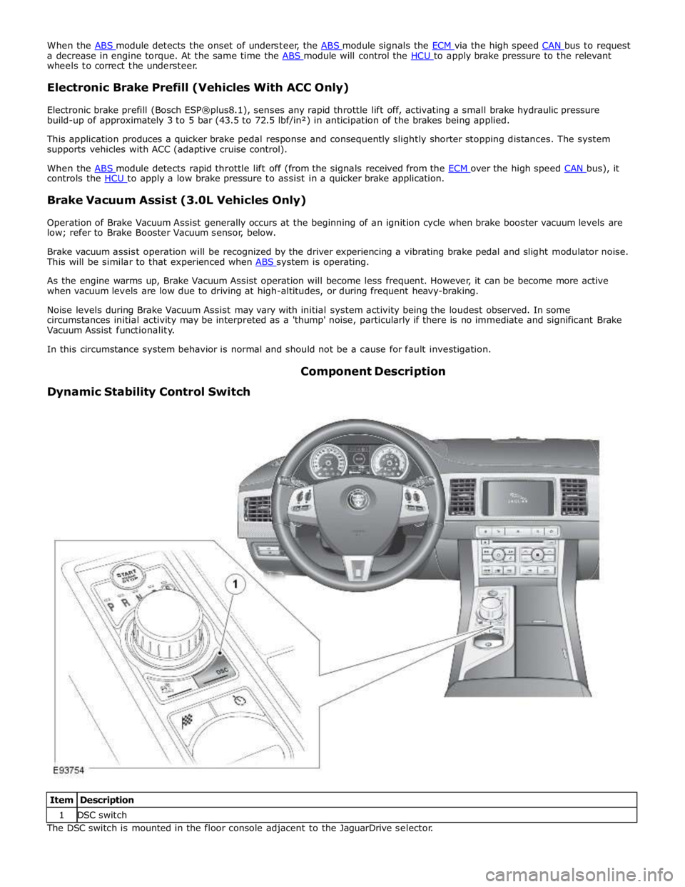
Dynamic Stability Control Switch Component Description
Item Description 1 DSC switch The DSC switch is mounted in the floor console adjacent to the JaguarDrive selector.