lock JAGUAR XJ 2004 X350 / 3.G Workshop Manual
[x] Cancel search | Manufacturer: JAGUAR, Model Year: 2004, Model line: XJ, Model: JAGUAR XJ 2004 X350 / 3.GPages: 227, PDF Size: 4.22 MB
Page 131 of 227
4-60 On the Road
Use of Headlamps In Daylight
When visibility is poor the headlamps
with dipped beam setting should be
switched on so that the vehicle may be
seen more easily by other road users.
The instrument illumination dimmer
control adjusts the brightness of the panel
lighting.
Engine Oil Consumption
A certain amount of oil consumption is
normal. The rate of consumption will
depend on the following:
• The quality and viscosity of the oil.
• The amount of oxidation and dilution of the oil.
• Climatic conditions.
• The speed at which the engine is being operated.
• Road conditions.
Drivers should expect above normal
consumption when the engine is new,
and after running-in if high speeds are
sustained.
Winter Driving
Freeing a frozen door lock
Caution: Do not ap ply a proprietary
lock de-icer through the keyhole.
Should the lock beco me frozen, warm the
end of the key before use.
Windscreen wiper blades
Before driving away, clear any ice from
the windscreen and check that the wiper
blades are free. Switching on the heated
screen will accelerate this process.
The heated wiper park, if fitted, will come
on automatically.
Frost precautions
The correct concentration of coolant
must be maintained at all times when
‘topping up’ or ‘refilling’ the cooling
system.
Parking the Vehicle
When leaving the vehicle, remember the
following:
• Whenever the vehicle is being parked, apply the parkbrake and move the
gear selector to Park ‘P’.
• Do not leave children or pets in the vehicle unattended.
• Do not leave luggage or valuables on view. Always take your valuables with
you or lock them in the luggage
compartment.
• Remove the ignition key and spare keys, even when the vehicle is in your
garage.
• When the vehicle is unoccupied, close
all windows and lock all doors
securely.
• Park the vehicle where it can be seen. At night, park in a well-lit area.
• Ensure that the keys and the key transmitters are removed from the
vehicle before locking the doors,
and that all doors, the luggage
compartment and the hood are
closed.
Page 134 of 227
On the Road 4 - 63
Fuel and Refuelling
Before refuelling, switch off the ignition
and remove the key.
Note:Do not leave the ignition key in the
vehicle; vehicles have been stolen from
garage service/filling stations whilst the
driver is absent from the vehicle. It is
recommended that the vehicle is locked,
if left unattended.
Caution: No additives of any kind
(fuel or oil) must be put into the fuel
tank. Additives could reduce engine
life or affect exhaust emissions.
!WARNING:
1. Fuel vapour is highly flammable and in confined spaces is
explosive and toxic. In the event
of inadvertent spillage, and before
refuelling, always switch OFF the
engine. Do not use exposed flame
or light. Do not smoke. Do not
inhale fumes.
2. Do not fill the tank so that fuel is visible in the fuel filler intake
tube. This could cause spillage
and danger from exposed fuel.
Fuel Tank Filling
Caution: Your vehicle is fitted with
catalytic converters and must only be
filled with ‘Unleaded Fuel’.
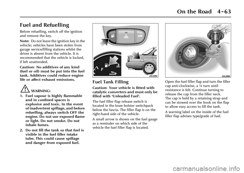
The fuel filler flap release switch is
located in the knee bolster switchpack
below the fascia. The fi ller flap is on the
right-hand side of the vehicle.
A small arrow is shown on the fuel gauge
as a reminder on which side of the
vehicle the fuel filler flap is located. Open the fuel filler flap and turn the filler
cap anti-clockwise, a ¼ turn until
resistance is felt. Continue turning to
release the cap from the filler neck.
The cap is held by a retaining strap and
can be stowed over the hook on the flap
to allow easy access to fill the tank.
A warning label on the inside of the fuel
filler flap advises type/grade of fuel.
Page 135 of 227
4-64 On the Road
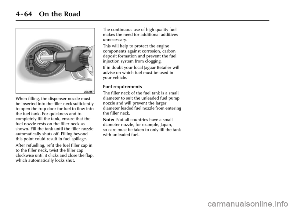
When filling, the dispenser nozzle must
be inserted into the filler neck sufficiently
to open the trap door for fuel to flow into
the fuel tank. For quickness and to
completely fill the ta nk, ensure that the
fuel nozzle rests on the filler neck as
shown. Fill the tank until the filler nozzle
automatically shuts off. Filling beyond
this point could result in fuel spillage.
After refuelling, refit the fuel filler cap in
to the filler neck, twist the filler cap
clockwise until it clicks and close the flap,
which automatically locks shut. The continuous use of high quality fuel
makes the need for a
dditional additives
unnecessary.
This will help to protect the engine
components against corrosion, carbon
deposit formation and prevent the fuel
injection system from clogging.
If in doubt your local Jaguar Retailer will
advise on which fuel must be used in
your vehicle.
Fuel requirements
The filler neck of the fuel tank is a small
diameter to suit the unleaded fuel pump
nozzle and will prevent the larger
diameter leaded fuel nozzle from entering
the filler neck.
Note: Not all countries have a small
diameter nozzle, for example, Japan,
so care must be taken to only fill the tank
with unleaded fuel.
Page 137 of 227
4-66 On the Road
Fuel filler flap manual release
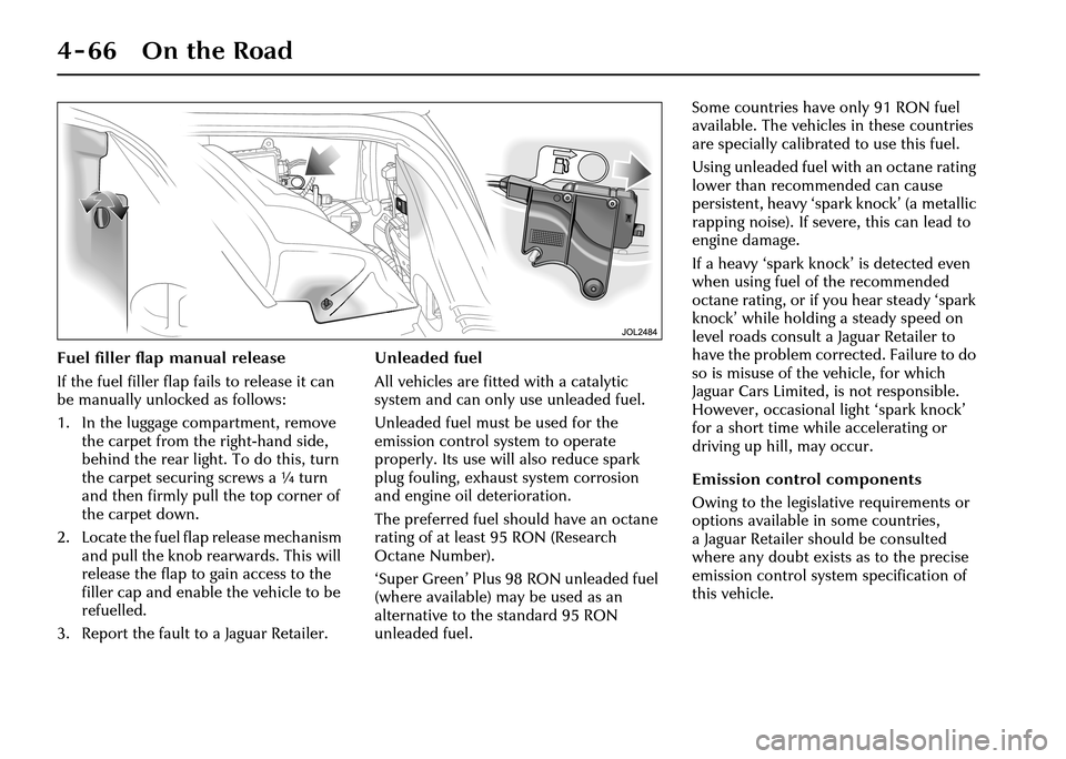
If the fuel filler flap fails to release it can
be manually unlocked as follows:
1. In the luggage compartment, remove
the carpet from the right-hand side,
behind the rear light. To do this, turn
the carpet securing screws a ¼ turn
and then firmly pull the top corner of
the carpet down.
2. Locate the fuel flap release mechanism and pull the knob rearwards. This will
release the flap to gain access to the
filler cap and enable the vehicle to be
refuelled.
3. Report the fault to a Jaguar Retailer. Unleaded fuel
All vehicles are fitted with a catalytic
system and can only use unleaded fuel.
Unleaded fuel must be used for the
emission control system to operate
properly. Its use will also reduce spark
plug fouling, exhaust system corrosion
and engine oil deterioration.
The preferred fuel should have an octane
rating of at least 95 RON (Research
Octane Number).
‘Super Green’ Plus 98 RON unleaded fuel
(where available) may be used as an
alternative to the standard 95 RON
unleaded fuel. Some countries have only 91 RON fuel
available. The vehicles in these countries
are specially calibrated to use this fuel.
Using unleaded fuel with an octane rating
lower than recomm
ended can cause
persistent, heavy ‘spark knock’ (a metallic
rapping noise). If severe, this can lead to
engine damage.
If a heavy ‘spark knock’ is detected even
when using fuel of the recommended
octane rating, or if you hear steady ‘spark
knock’ while holding a steady speed on
level roads consult a Jaguar Retailer to
have the problem corrected. Failure to do
so is misuse of the vehicle, for which
Jaguar Cars Limited, is not responsible.
However, occasional light ‘spark knock’
for a short time while accelerating or
driving up hill, may occur.
Emission control components
Owing to the legislative requirements or
options available in some countries,
a Jaguar Retailer should be consulted
where any doubt exists as to the precise
emission control system specification of
this vehicle.
Page 143 of 227
5 - 4 Climate Control
In AUTO mode, the air intake flap is
controlled automatically. If required,
air recirculation may be manually
selected for either a short or indefinite
period.
Air Recirculation
Timed air recirculationPress the button briefly to select
timed air recirculation.
The fresh air intake is opened
and the button LED extinguished at the
end of the time out period.
Latched air re circulation
Press and hold the button for a
few seconds to select latched air
recirculation. Selection is
indicated by the scre en symbol and two
beeps.
Selecting latched air recirculation cancels
AUTO operation.
To deselect latched air recirculation,
press the recirculat ion button again,
or select AUTO.
!WARNING:
To prevent humidity build up inside
the vehicle and possible screen
misting, avoid driving with the air
conditioning system off or with
manual air recirculation selected for
prolonged periods.
General Points
To ensure the satisfactory operation of
the climate control system, note the
following points:
• Ensure that the external grille at the base of the windscreen, which
provides fresh air for the climate
control system, is kept clear of leaves,
snow or obstructions.
• A solar sensor is mounted on the centre top of the fascia, as shown
opposite ( A) . E n s u r e t h a t this sensor is
not covered.
• Temperature and humidity sensors are located behind the small grille ( B).
Do not cover or obstruct the opening.
• Air ducts under the front seats supply the rear passenger footwells (see
illustration opposite). Objects or
material placed under the seats may
block or obstruct the open ducts. • The external air intake to the air
conditioner/heater system is fitted
with a filter. Ensure that the filter is
changed at the specified service
intervals to maintain efficient
operation.
• If the air conditioning system is not used frequently, it should be run
briefly at least once each week, with a
cold setting, to prevent the seals from
drying out with subsequent
refrigerant leaks.
• Moisture removed from the air by the air conditioning unit is discharged
onto the road underneath the vehicle.
After stopping, puddles of water may
form underneath the vehicle.
Air Distribution
The illustration opposite shows the
location of the air vents within the
vehicle. The airflow from the fascia face
level vents is regulated using thumbwheel
controls and adjustable direction vanes.
Air distribution between the windscreen,
fascia and floor levels is selected
automatically when operating in AUTO
mode but can be selected manually.
Page 158 of 227

Roadside Emergency 6 - 7
Locking Wheel Nuts
Where Jaguar locking wheel nuts are
fitted (one on each wheel), they can only
be removed using the correct key socket.
The locking wheel nut comprises two
grooved parts, front and rear, which must
be turned together to allow the nut to be
fitted or removed.
To remove the nut, the front and rear
grooves must be aligned. Locate the key
socket in the grooves and push it fully
over both parts of the nut. Fit the wheel
nut wrench over the key socket and
loosen the locking wheel nut (turn anti-
clockwise). Attempting to remove the nut without the
correct key socket
(such as attempted
theft) or with the socket not located over
the rear part of the nut, will cause the
front part only ( A) to turn.
If this has happened, rotate the front part
with the key socket until the grooves are
re-aligned and then push the socket fully
over the nut.
Should a new key socket be required,
contact your Jaguar Retailer. Proof of
vehicle ownership will be required.
Page 159 of 227

6 - 8 Roadside Emergency
Spare Wheel and Jack Removal
!WARNING:
Wheels are extremely heavy.
Take care when lifting and
particularly when removing and
replacing a wheel in its storage
position in the luggage compartment.
The spare wheel and jacking equipment
are stored under the trunk floor panel.
Seepage6-4.
To remove the spare wheel, fully unscrew
the locking ring ( A). Unscrew the wing
nut below the locking ring. This allows
wheel retainer ( B) to be lifted and
removed. The wheel can now be lifted
out.
Page 161 of 227

6 - 10 Roadside Emergency
!WARNING:
1. Do not attempt to lift the vehicle unless the jack head is fully
engaged in the jacking point.
2. Ensure that the parkbrake is applied.
Place the jack squarely beneath the
appropriate jacking point. Ensure that the
jack head is fully engaged. Carefully raise
the vehicle by turning the handle.
Stop jacking the vehicle when the tyre
just clears the ground. Minimum tyre lift
gives maximum vehicle stability.
Remove the wheel nuts and the wheel.
Centre badge
When changing the alloy road wheels,
transfer the centre badge to the
replacement wheel. Using the plastic
tipped end of the wheel nut wrench
handle from the inside of the wheel, push
the centre badge from its housing.
Push the centre badge into the
replacement wheel. Fitting the spare wheel
Fit the spare wheel and loosely secure
with the wheel nuts.
Using the wheel nut wrench, lightly
tighten the wheel nuts
alternately using
the sequence shown in the illustration.
Lower the jack and ti ghten the wheel nuts
alternately, DO NOT OVER TIGHTEN.
At the earliest opportunity have the
wheel nuts tightened with a torque
wrench to 92 lb.ft (125 Nm).
This torque must not be exceeded. Stowing the equipment
Stow the replaced road wheel in the
trunk.
Check that the locking ring is unscrewed
fully so that it is as close as possible to the
handle of the wheel retainer. This is to
ensure that the wheel retainer can be
fitted correctly.
Locate the wheel retainer into its mating
thread in the trunk floor and tighten it
fully, then tighten the locking ring
clockwise to secure the wheel.
Seepage6-8.
Stow the jacking equipment.
Close the trunk floor panel.
!WARNING:
When a temporary spare wheel is
fitted, drive with caution and replace
with the specified wheel and tyre as
soon as possible.
Page 163 of 227
6 - 12 Roadside Emergency
Transporter tie-down procedure
!WARNING:
Avoid body contact with a hot
exhaust pipe when securing the
vehicle to the transporter.
IMPORTANT – Use straps over the
wheels/tyres only, to secure the vehicle to
the transporter.
Caution: Do not use the tie-down
brackets on the vehicle rear
underbody; these are for Jaguar
factory use only. In time, with the
engine switched off, the vehicle body
will drop due to settling of the air
suspension system and cause the tie-
down chains/straps to become slack if
connected to these brackets.
The towing eye is not designed for
securing the vehicle during
transportation. Vehicle failure
The removable towing eye is primarily for
emergency use when towing for SHORT
DISTANCES, e.g. removing the vehicle if it
is causing an obstruct
ion or for winching
the vehicle onto a re covery transporter.
To prevent damage to the automatic
transmission whilst the vehicle is being
towed with the rear wheels on the
ground, towing distance must be
restricted to 0.5 miles (0.8 kilometres).
Towing speed must not exceed 30 mph
(48 km/h).
Always obey towing regulations.
In certain countries the registration
number of the towing vehicle and an
‘ON TOW’ sign or warning triangle must
be displayed in a prominent position at
the rear of the vehicle being towed. When being towed, the gear selector
lever must be in neutral (position ‘N’)
with the ignition key turned to
position ‘II’ to release the steering lock
and render the indicators, horn and
brake lights operational.
!WARNING:
When the engine is not running the
steering and brakes will no longer be
power-assisted.
Therefore, be prepared for relatively
heavy steering and the need for
greatly increased brake pedal
pressure.
Page 164 of 227

Roadside Emergency 6 - 13
Towing Eye
A screw-in towing eye is provided in the
trunk with the jack and can be fitted to
the front or rear of the vehicle.
The towing eye has a left-hand thread
and must be turned in an anti-clockwise
direction when fitting.
Caution:
1. The towing eye is not suitable for ‘solid bar’ towing.
2. Care must be taken to avoid damaging the bumpers and front
apron. Front tow point
The front tow point is located behind a
plastic cover (shown
above) on the left-
hand side of the vehicle, as viewed from
the front.
To remove the cover, unclip the top edge,
pivot down and unclip the bottom edge.
Screw the towing ey e into the vehicle,
right up to the shoulder, turning anti-
clockwise.
To refit the cover (towing eye removed)
first clip the lower edge to the bumper
aperture, pivot up and press the top edge
into position. Rear tow point
!WARNING:
Avoid body contact with a hot
exhaust pipe when fitting the eye to
the rear towing point.
The rear tow point is alongside the left-
hand exhaust pipe.
Screw the towing eye into the vehicle,
right up to the shoulder, turning anti-
clockwise.