ECO mode JAGUAR XJ6 1994 2.G Electrical Diagnostic Manual
[x] Cancel search | Manufacturer: JAGUAR, Model Year: 1994, Model line: XJ6, Model: JAGUAR XJ6 1994 2.GPages: 327, PDF Size: 13.73 MB
Page 80 of 327
Climate Control Systems
14.2.8 Heater Matrix Temperature Sensor
This sensor is positioned inside the air conditioning unit just
downstream of the heater matrix. The sensor monitors the
post
-heater air temperature, before the air is distributed to
the passenger compartment. In conjunction with the A / CCM this sensor provides the input to maintain a constant
outlet temperature.
14.2.9 Coolant Temperature Signal
This input is required to provide blower inhibit control, to
avoid cold
air being delivered in heating mode when the en- gine coolant temperature is below 3OOC. The input also
monitors the temperature of the coolant delivered to the
heater matrix to assist outlet temperature control.
14.2. IO Compressor ON Signal
This signal line monitors the compressor relay to inform the
A/ CCM of the compressor status and to facilitate lock detec-
tion and error sensing.
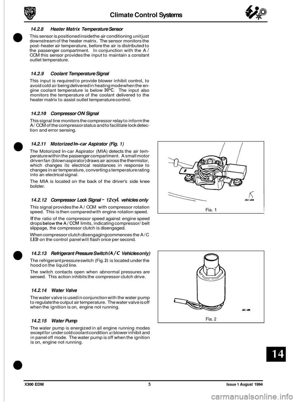
14.2.11 Motorized In-car Aspirator (Fig. 1)
The Motorized In-car Aspirator (MIA) detects the air tem- perature within the passenger compartment. A small motor
driven fan (blown aspirator) draws air across the thermistor,
which changes its electrical resistances in response to
changes in air temperature, converting
a temperature rating
into an electrical signal.
The MIA is located on the back of the driver's side knee
bolster.
14.2.12 Compressor Lock Signal - 12 cy/. vehicles only
This signal provides the A / CCM with compressor rotation
speed. This is then compared with engine rotation speed.
If the ratio of the compressor speed against engine speed
drops belowthe A/CCM limits, indicating compressor/ belt
slippage, the compressor clutch is disengaged.
When compressor clutch disengaging commences the A/C
LED on the control panel will flash once per second.
14.2.13 Refrigerant Pressure Switch (A/C Vehicles only)
The refrigerant pressure switch (Fig. 2) is located under the
hood on the liquid line.
The switch contacts open when abnormal pressures are
sensed. This action inhibits the compressor clutch drive.
14.2.14 Water Valve
The water valve is used in conjunction with the water pump
to regulate the output air temperature. The water valve is off when the ignition is on, engine not running.
14.2.15 Water Pump
The water pump is energized in all engine running modes
except for under cold coolant condition at blower inhibit and
in panel
off mode. The water pump is off when the ignition
is on, engine not running.
If
J82-488
KI Fia. 1 I
Fia. 2
X300 EDM 5 Issue 1 August 1994
Page 85 of 327
Climate Control Systems
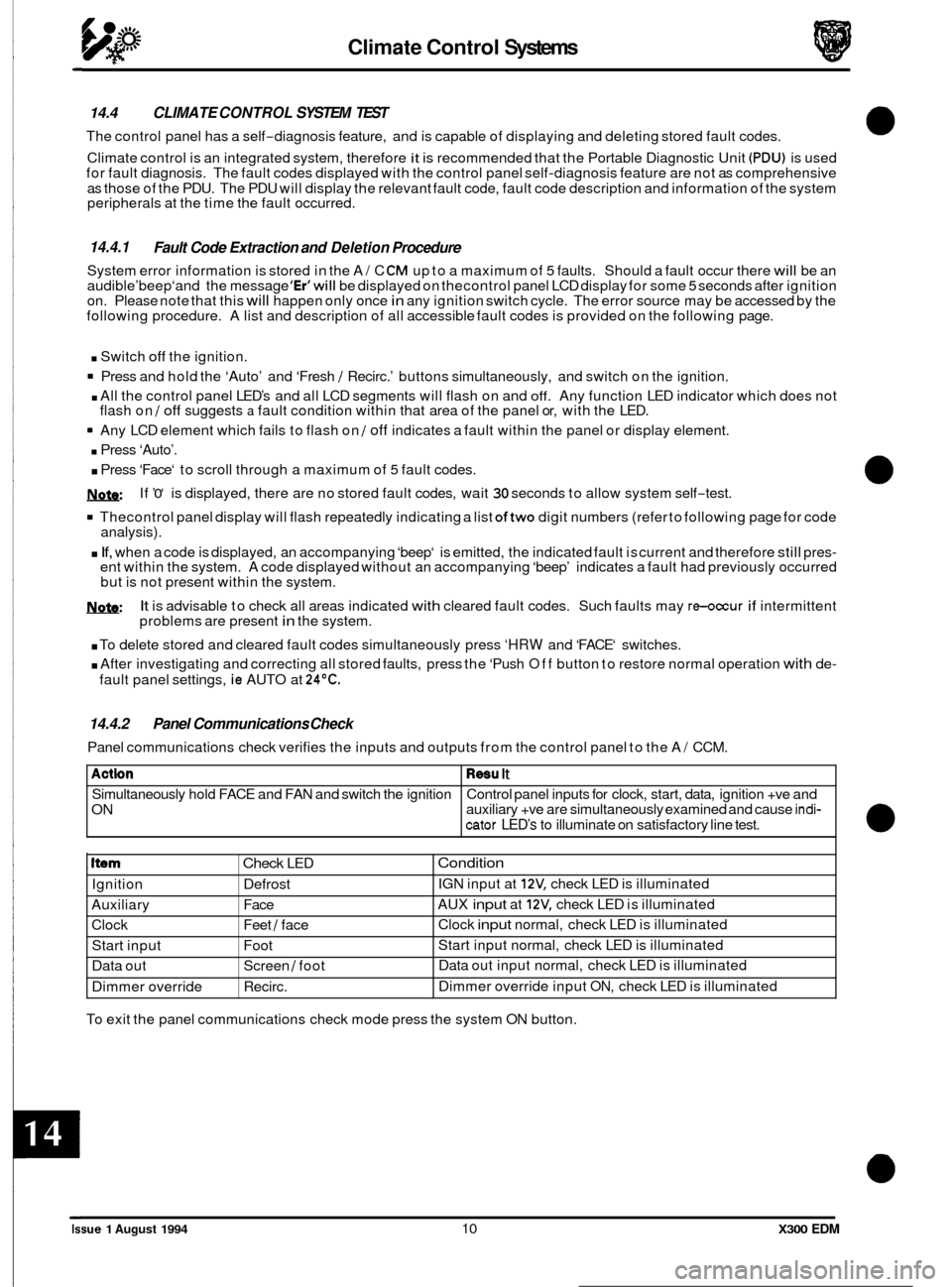
Actlon
Simultaneously hold FACE and FAN and switch the ignition
ON
14.4 CLIMATE CONTROL SYSTEM TEST
The control panel has a self-diagnosis feature, and is capable of displaying and deleting stored fault codes.
Climate control is an integrated system, therefore
it is recommended that the Portable Diagnostic Unit (PDU) is used
for fault diagnosis. The fault codes displayed with the control panel self-diagnosis feature are not as comprehensive
as those of the PDU. The PDU will display the relevant fault code, fault code description and information of the system
peripherals at the time the fault occurred.
Resu It
Control panel inputs for clock, start, data, ignition +ve and
auxiliary +ve are simultaneously examined and cause indi-
cator LED’s to illuminate on satisfactory line test.
14.4.1
System error information is stored in the A/ C CM up to a maximum of 5 faults. Should a fault occur there will be an
audible’beep‘and the message ‘Er’will be displayed on thecontrol panel LCD display for some 5 seconds after ignition
on. Please note that this will happen only once in any ignition switch cycle. The error source may be accessed by the
following procedure. A list and description of all accessible fault codes is provided on the following page.
Fault Code Extraction and Deletion Procedure
I Item Check LED
Ignition Defrost
Auxiliary Face
Clock Feet
/ face
Start input Foot
Data out Screen
/ foot
Dimmer override Recirc.
. Switch off the ignition.
Press and hold the ‘Auto’ and ‘Fresh / Recirc.’ buttons simultaneously, and switch on the ignition.
. All the control panel LED’s and all LCD segments will flash on and off. Any function LED indicator which does not
flash on / off suggests a fault condition within that area of the panel or, with the LED.
Any LCD element which fails to flash on
/ off indicates a fault within the panel or display element.
. Press ‘Auto’.
. Press ‘Face‘ to scroll through a maximum of 5 fault codes.
W
Thecontrol panel display will flash repeatedly indicating a list oftwo digit numbers (refer to following page for code
analysis).
. If, when a code is displayed, an accompanying ‘beep‘ is emitted, the indicated fault is current and therefore still pres- ent within the system. A code displayed without an accompanying ‘beep’ indicates a fault had previously occurred
but is not present within the system.
It is advisable to check all areas indicated with cleared fault codes. Such faults may re-occur if intermittent
problems are present in the system.
If
’0‘ is
displayed, there are no stored fault codes, wait 30 seconds to allow system self-test.
W:
. To delete stored and cleared fault codes simultaneously press ‘HRW and ‘FACE‘ switches.
. After investigating and correcting all stored faults, press the ‘Push Off button to restore normal operation with de-
fault panel settings, ie AUTO at 24OC.
Condition
IGN input at 12V, check LED is illuminated
AUX
input at 12V, check LED is illuminated
Clock
input normal, check LED is illuminated
Start input normal, check LED is illuminated
Data out input normal, check LED is illuminated
Dimmer override input
ON, check LED is illuminated
14.4.2 Panel Communications Check
Panel communications check verifies the inputs and outputs from the control panel to the A/ CCM.
To exit the panel communications check mode press the system ON button.
Issue 1 August 1994 10 X300 EDM
Page 87 of 327
Climate Control Systems
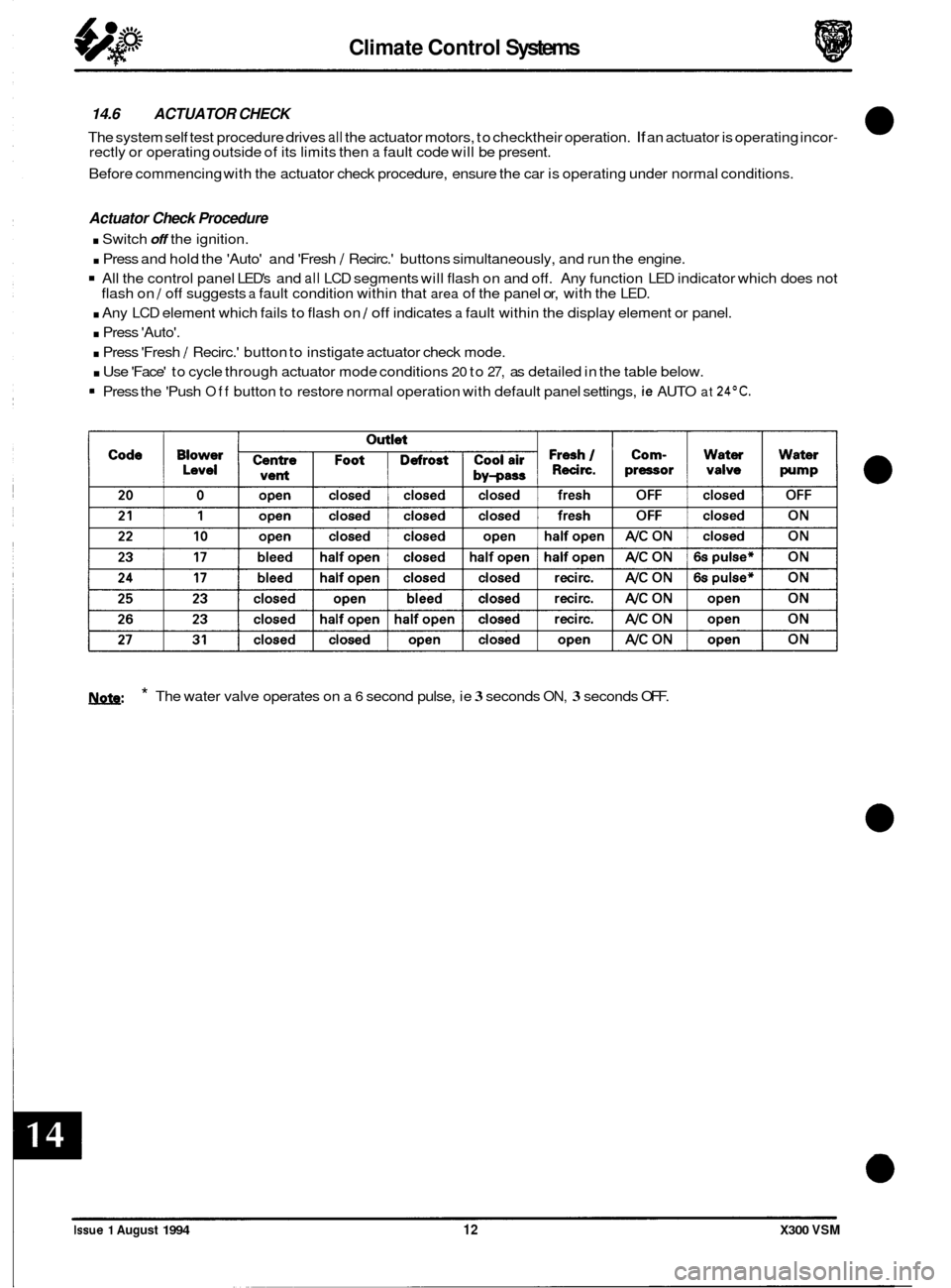
14.6 ACTUATOR CHECK
The system self test procedure drives all the actuator motors, to checktheir operation. If an actuator is operating incor- rectly or operating outside of its limits then a fault code will be present.
Before commencing with the actuator check procedure, ensure the car is operating under normal conditions.
Actuator Check Procedure
. Switch off the ignition.
. Press and hold the 'Auto' and 'Fresh / Recirc.' buttons simultaneously, and run the engine.
All the control panel LED's and all LCD segments will flash on and off. Any function LED indicator which does not
. Any LCD element which fails to flash on / off indicates a fault within the display element or panel.
. Press 'Auto'.
. Press 'Fresh / Recirc.' button to instigate actuator check mode.
. Use 'Face' to cycle through actuator mode conditions 20 to 27, as detailed in the table below.
flash
on
/ off suggests a fault condition within that area of the panel or, with the LED.
Press the 'Push Off button to restore normal operation with default panel settings, ie AUTO at 24OC.
1ynfe: * The water valve operates on a 6 second pulse, ie 3 seconds ON, 3 seconds OFF.
Issue 1 August 1994 12 X300 VSM
Page 102 of 327
Electrical IT
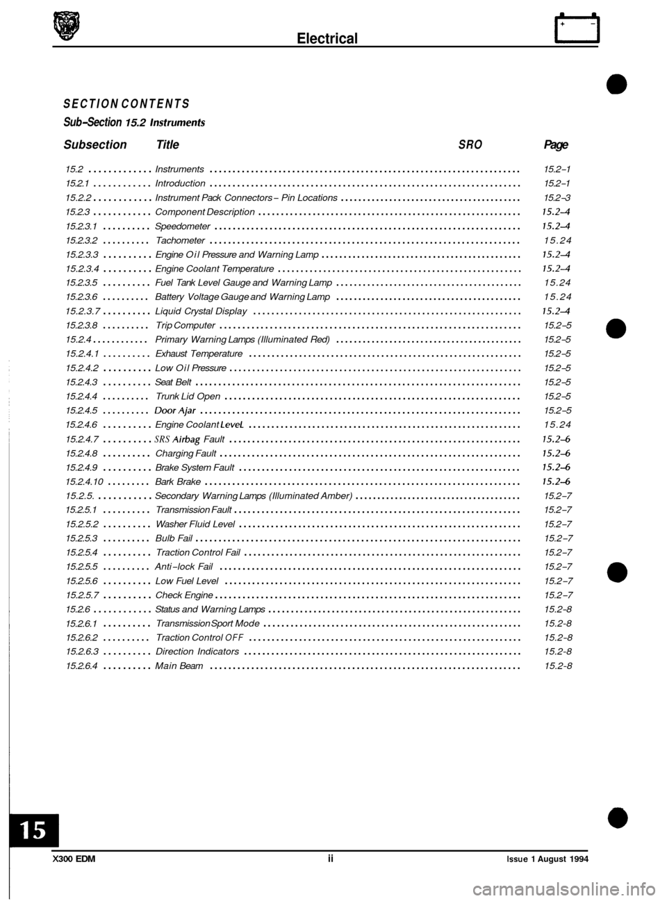
SECTION CONTENTS
Sub
-Section 15.2 lnsfrumenfs
Subsection Title SRO Page
15.2 ............. Instruments .................................................................... 15.2-1
15.2.1
............ Introduction .................................................................... 15.2-1
15.2.2
............ Instrument Pack Connectors - Pin Locations ......................................... 15.2-3
15.2.3
............ Component Description .......................................................... 15.24
15.2.3.1 .......... Speedometer ................................................................... 15.24
15.2.3.2 .......... Tachometer .................................................................... 15.24
15.2.3.3
.......... Engine Oil Pressure and Warning Lamp ............................................. 15.24
15.2.3.4 .......... Engine Coolant Temperature ...................................................... 15.24
15.2.3.5 .......... Fuel Tank Level Gauge and Warning Lamp .......................................... 15.24
15.2.3.6
.......... Battery Voltage Gauge and Warning Lamp .......................................... 15.24
15.2.3.7
.......... Liquid Crystal Display ........................................................... 15.24
15.2.3.8 .......... Trip Computer .................................................................. 15.2-5
15.2.4
............ Primary Warning Lamps (Illuminated Red) .......................................... 15.2-5
15.2.4.1
.......... Exhaust Temperature ............................................................ 15.2-5
15.2.4.2
.......... Low Oil Pressure ................................................................ 15.2-5
15.2.4.3
.......... Seat Belt ....................................................................... \
15.2-5
15.2.4.4
.......... Trunk Lid Open ................................................................. 15.2-5
15.2.4.5
.......... DoorAjar ...................................................................... 15.2-5
15.2.4.6
.......... Engine Coolant LeveL ............................................................ 15.24
15.2.4.7
.......... SRS Airbag Fault ................................................................ 15.24
15.2.4.8 .......... Charging Fault .................................................................. 15.24
15.2.4.9 .......... Brake System Fault .............................................................. 15.24
15.2.4.10 ......... Bark Brake ..................................................................... 15.24
15.2.5. ........... Secondary Warning Lamps (Illuminated Amber) ...................................... 15.2-7
15.2.5.1
.......... Transmission Fault ............................................................... 15.2-7
15.2.5.2
.......... Washer Fluid Level .............................................................. 15.2-7
15.2.5.3
.......... Bulb Fail ....................................................................... \
15.2-7
15.2.5.4
.......... Traction Control Fail ............................................................. 15.2-7
15.2.5.5
.......... Anti-lock Fail .................................................................. 15.2-7
15.2.5.6
.......... Low Fuel Level ................................................................. 15.2-7
15.2.5.7
.......... Check Engine ................................................................... 15.2-7
15.2.6.1
.......... Transmission Sport Mode ......................................................... 15.2-8
15.2.6.2
.......... Traction Control OFF ............................................................ 15.2-8
15.2.6.3
.......... Direction Indicators ............................................................. 15.2-8
15.2.6.4
.......... Main Beam .................................................................... 15.2-8
15.2.6
............ Status
and Warning Lamps ........................................................ 15.2-8
m
a
0
e
0
X300 EDM ii Issue 1 August 1994
Page 190 of 327
15.4 DRIVER ERGONOMICS
15.4.1 System Description
Adjustment of the seats, steering column and exterior rear view mirrors position is effected by means of control
switches. The switches maintain the adjustment facility while depressed, movement ceasing when the switch is re- leased.
Manual adjustment can be achieved either with the ignition key in place or with the driver‘s door open, or having been
closed within the last
30 seconds.
The system offers the following facilities:
Entry
/ Exit mode; an automatic seat /column position setting for ease of driver entry into / exit from the vehicle.
Driving position set; automatic recall of up to three preferred settings.
Passenger seat set; automatic recall of up to three preferred settings.
Remote recall; automatic recall of up to two memory positions from
a remote transmitter (in key fob).
Reverse mirror dip; automatic adjustment of passenger rear view mirror when reversing.
U: Vehicles intended for the Japanese market are fitted with an additional ‘fold away’ mirror function. This func- tion allows mirrors to fold flat against the car when parking in enclosed areas.
15.4.1.1 Entry/ Exit Mode
Entry / Exit mode is designed to give easier vehicle entry and exit for the driver. The facility is selected by positioning
the mode switch, located on the LH side of the column cowl, to ‘auto’ which designates the current seat / column posi- tion, ie driving positions, as the memorized position. On removal of ignition key or opening of driver‘s door, with igni- tion key still in place, the driver’s seat will move to the rear (current position allowing) and the column will adopt ‘tilt
away’ mode automatically creating additional space for driver exit
/ entry. Insertion of key in ignition or closure of
driver‘s door (with ignition key in place) returns seat / column positions to the memorized (previous) position.
Operation of eitherthe brake pedal or
seat/column manual controls during entry/exit mode execution will abort posi- tional adjustments. Setting the mode switch to OFF disables operation of entry / exit mode.
15.4.1.2 Driving Position Set
Setting of seat, column and external rear view mirrors to preferred driving position is available using the memory but- tons located on the drivers door switch pack. With the ignition key in place enter settings to be memorized as follows:
Adjust seat, column and mirrors to desired positions.
Press the ’memory’ button
so that it becomes illuminated.
Press button
1,2 or 3 to store configuration within four seconds of memory button operation. Memory light will extin- guish and a chime will sound, indicating procedure complete.
The above procedure may be repeated two more times until each button
(1,2 & 3) has a preferred position stored in
memory, accommodating different driver settings. Operation of any push-button (1,2 or 3) will re-position seat col-
umn and mirrors to the stored settings.
Memory recall will operate under the following conditions:
. Ignition key in and gear selector in park.
8 Ignition key in and handbrake on.
8 Ignition key out and driver’s door open (or having been closed within the last 30 seconds).
Re
-setting the preferred position on any setting button automatically erases previously stored information. Memory
information is not erased if power supply to the seat and column / mirror control modules is lost (e.g. battery discon- nected).
15.4.1.3 Passenger Seat Set
The procedure for setting and recalling a preferred passenger seat position is identical to that for a driving position.
Memory recall will only operate with ignition key in auxiliary position or passenger door open, or having been closed
within the last
30 seconds.
X300 EDM 15.4 - 1 Issue 1 August 1994
Page 210 of 327
E I ect r ica I
15.4.7 SYMPTOM FLOW CHARTS
The following test procedures are designed to test the system as a whole, identifying faulty areas and indicating poss- ible solutions by functional operations.
During all test procedures the entry
/ exit mode switch must be OFF.
The first three test procedures listed i.e. drivers seat position adjustments, steering column position adjustments, rear
view mirror position adjustments must be carried out four times, each time under one of the conditions stated below:
Key in ignition barrel
Ignition key in auxiliary position
Driver’s door open with ignition key out
Driver’s door closed within the last 30 seconds with ignition key out.
0
Driver‘s seat position adjustments
1.
2.
3.
0
4.
5.
6.
7.
0
Locate seat switch pack on the side of the seat cushion.
Operate the fore
/ aft movement control switch. Does the seat respond in the correct
manner?
Yes: Proceed to step 3.
No:
Operate front and rear, raise / lower movement control switches. Does seat respond in the
correct manner in each case?
Yes: Proceed to step 4.
No:
Operate squab recline / incline movement control switch. Does squab respond in correct
manner?
Yes: Proceed to step 5.
No:
Operate lumbar pump inflate / deflate control switch. Does lumbar pad stiffen and slacken
according
I y?
Yes: Proceed to step 6
No:
Operate headrest raise / lower switch. Does headrest respond in correct manner?
Yes: proceed to step
7.
No:
Remove key from ignition, close driver‘s door and allow 30 seconds to elapse. Repeat
steps
1 - 6 and check that adjustment cannot be made.
Test complete; proceed to Memory Position Set.
Abort
test and refer to Diagnostic Sub
-Routines.
Abort test and refer to Diagnostic Sub
-Routines.
Abort test and refer to Diagnostic Sub
-Routines.
Abort test and refer to Diagnostic Sub
-Routines.
Abort test and refer to Diagnostic Sub
-Routines.
Steering column position adjustments
1.
2.
Locate steering column joystick switch the LH side of the column.
Operate switch to give fore
/ aft movement. Does the column respond in correct manner?
Yes: Proceed to step 3.
No:
Operate the switch to give raise / lower movement. Does column respond in the correct
manner in each case?
Yes: Proceed to step 4.
No:
Remove key from ignition, close driver’s door and allow 30 seconds to elapse. Repeat
steps 1
- 3 and check that adjustment cannot be made.
Test complete; proceed to Memory Position Set.
Abort
test and refer to Diagnostic Sub
-Routines.
3.
Abort test and refer to Diagnostic Sub-Routines.
4.
5.
X300 EDM 15.4 - 13 Issue 1 August 1994
Page 211 of 327
Rear view mirror position adjustments
1. Locate mirror select switch on driver's door switch pack and select driver's side mirror, ie
rotate switch towards the door.
2. Locate rear view mirror joystick switch on driver's door pack.
Operate the switch to give left
/ right and up / down movement. Does the mirror respond
in the correct manner?
3. Yes: Proceed to step 4 or 5.
No:
Japanese market vehicles only
Operate the switch to action 'fold away mode'. Does mirror respond in the correct manner
in each case?
Yes: Proceed to step
5.
No:
All markets
Operate mirror select switch to opposite position and repeat steps
1 to 4 for passenger side
mirror.
With ignition switched to auxiliary, select reverse gear and operate mirror joy
-stick
downwards. Does passenger side mirror dip automatically?
Yes: Proceed to step
7.
No:
Remove key from ignition, close driver's door and allow 30 seconds to elapse. Repeat
steps
1 - 6 and check that adjustment cannot be made.
Test complete; proceed to Memory Position Set.
Abort
test and refer to Diagnostic Sub
-Routines.
4.
Abort test and refer to Diagnostic Sub-Routines.
5.
6.
Abort test and refer to Diagnostic Sub-Routines.
7.
8.
Memory set position - drivefs side
1.
2.
3.
4.
5.
6.
7.
8.
Position the entry / exit switch, located on the LH side of the steering column, to off and
insert the key in the ignition.
Operate switches to position column, mirrors and seats to preferred positions.
Select 'memory' on the driver's door switch pack. Check that switch illuminates.
Depress desired memory button,
1,2 or 3, on door switch pack within 4 seconds of
memory select. Check that a chime sounds to confirm memory storage.
Operate the switches
so that memorized positions are changed. Depress relevant memory
option button,
1,2 or 3 and check that all positional settings are restored as memorized.
Remove key from ignition, close all doors and allow
30 seconds to elapse. Repeat steps 1
to 4 and check that adjustment cannot be made.
Readjust settings so that memorized positions are changed, leave the vehicle and operate
remote memory recall by locking and unlocking using the remote transmitter. Use both
transmitters to check both memory positions. Check all positional settings are restored as
memorized.
Yes: Proceed to step
8.
No:
Test complete. Abort
test and refer to Diagnostic Sub
-Routines.
X300 EDM Issue 1 August 1994 15.4 - 14